HIKOKI CJ 36DA Handling Instructions Manual
Hide thumbs
Also See for CJ 36DA:
- Handling instructions manual (36 pages) ,
- Handling instructions manual (25 pages) ,
- Handling instructions manual (296 pages)

Related Manuals for HIKOKI CJ 36DA


Summary of Contents for HIKOKI CJ 36DA
- Page 1 充电式曲线锯 Cordless Jig Saw CJ 36DA 保留备用 Keep for future reference 使用说明书 Handling instructions...
-
Page 2: Table Of Contents
中文 目次 电动工具通用安全警告 ..................2 电动曲线锯安全警告 ..................5 使用充电式曲线锯时应注意事项 ..............5 锂离子电池使用注意事项 ................7 锂离子电池运输 ....................8 USB设备连接器使用注意事项 ................. 8 符号 ........................ 9 零件名称 ......................9 规格 ......................10 标准附件 ....................... 10 用途 ......................11 电池的拆卸/安装法 ..................11 充电 ......................11 作业之前... - Page 3 中文 b) 不要在易爆环境,如有易燃液体、气体或粉尘的环境下操作电动工具。 电动工具产生的火花会点燃粉尘或气体。 c) 让儿童和旁观者离开后操作电动工具。 注意力不集中会使操作者失去对工具的控制。 2) 电气安全 a) 电动工具插头必须与插座相配。绝不能以任何方式改装插头。需接地的 电动工具不能使用任何转换插头。 未经改装的插头和相配的插座将减少电击危险。 b) 避免人体接触接地表面,如管道、散热片和冰箱。 如果你身体接地会增加电击危险。 c) 不得将电动工具暴露在雨中或潮湿环境中。 水进入电动工具将增加电击危险。 d) 不得滥用电线。绝不能用电线搬运、拉动电动工具或拔出其插头。使电 线远离热源、油、锐边或运动部件。 受损或缠绕的软线会增加电击危险。 e) 当在户外使用电动工具时,使用适合户外使用的外接软线。 适合户外使用的软线将减少电击危险。 f) 如果在潮湿环境下操作电动工具是不可避免的,应使用剩余电流动作保 护器(RCD) 。 使用RCD可减小电击危险。 3) 人身安全 a) 保持警觉,当操作电动工具时关注所从事的操作并保持清醒。当你感到 疲倦,或在有药物、酒精或治疗反应时,不要操作电动工具。 在操作电动工具时瞬间的疏忽会导致严重人身伤害。 b) 使用个人防护装置。始终佩戴护目镜。 安全装置,诸如适当条件下使用防尘面具、防滑安全鞋、安全帽、听力 防护等装置能减少人身伤害。...
- Page 4 中文 g) 如果提供了与排屑、集尘设备连接用的装置,要确保它们连接完好且使 用得当。 使用这些装置可减少尘屑引起的危险。 h) 请勿因频繁使用工具的熟悉感而掉以轻心,忽视工具的安全性原则。 粗心的行为可能会导致瞬间发生严重伤害。 4) 电动工具使用和注意事项 a) 不要滥用电动工具,根据用途使用适当的电动工具。 选用适当设计的电动工具会使你工作更有效、更安全。 b) 如果开关不能接通或关断工具电源,则不能使用该电动工具。 不能用开关来控制的电动工具是危险的且必须进行修理。 c) 在进行任何调整、更换附件或存放电动工具之前,必须从电源上拔掉插 头和/或取下电池盒(如果可拆卸) 。 这种防护性措施将减少工具意外起动的危险。 d) 将闲置不用的电动工具贮存在儿童所及范围之外,并且不要让不熟悉电 动工具或对这些说明不了解的人操作电动工具。 电动工具在未经培训的用户手中是危险的。 e) 维护电动工具和附件。检查运动件是否调整到位或卡住,检查零件破损 情况和影响电动工具运行的其他状况。如有损坏,电动工具应在使用前 修理好。 许多事故由维护不良的电动工具引发。 f) 保持切削刀具锋利和清洁。 保养良好的有锋利切削刃的刀具不易卡住而且容易控制。 g) 按照使用说明书,考虑作业条件和进行的作业来使用电动工具、附件和 工具的刀头等。 将电动工具用于那些与其用途不符的操作可能会导致危险。 h) 保持手柄和抓握表面干燥、清洁,远离油和油脂。 如果手柄和抓握表面湿滑,可能导致在发生意外情况时,无法安全操作 和控制工具。...
-
Page 5: 电动曲线锯安全警告
中文 e) 请勿使用损坏或改装的电池盒或工具。 损坏或改装的电池可能会引发突发状况,导致火灾、爆炸或受伤。 f) 请勿将电池盒或工具暴露在有火源或高温环境中。 如果暴露在有火源或 130 度以上高温的环境中,可能引起爆炸。 g) 请完全按照充电说明进行操作,不要在说明中规定的温度范围外的环境 中对电池盒或工具充电。 充电不当或在规定温度范围外的环境中充电可能会导致电池损坏,增加 发生火灾的风险。 6) 维修 a) 将你的电动工具送交专业维修人员,使用同样的备件进行修理。 这样将确保所维修的电动工具的安全性。 b) 请勿维修已损坏的电池盒。 需由制造商或经授权的服务供应商进行维修。 注意! 不可让儿童和体弱人士靠近工作场所。 应将不使用的工具存放在儿童和体弱人士接触不到的地方。 电动曲线锯安全警告 1. 当在切削附件有可能碰到暗线的场所进行操作时,只能通过绝缘握持面来握 住电动工具。 切削附件碰到带电导线可能会使电动工具的外露金属零件带电并使操作者发 生电击危险。 使用充电式曲线锯时应注意事项 1. 务请在 0℃~ 40℃的温度下进行充电。温度低于 0℃将会导致充电过度,极 其危险。电池不能在高于 40℃的温度下充电。 最适合于充电的温度是 20 ~ 25℃。 2. - Page 6 中文 8. 充电后电池寿命太短不够使用时,请尽快将电池送往经销店。请勿将用过的 电池乱丢。 9. 请勿使用耗竭了的电池,否则会损坏充电器。 10. 如果以低速持续使用本机,则电动机被加载额外负载,这可能会导致电动机 卡死。经常对电动工具进行操作以防在作业中锯片被材料卡住。经常调整锯 片速度以顺利切割。 11. 长时间连续使用本电钻,可能会导致机体过热,对马达及开关造成损害,因 此使用本机请勿连续超过 15 分钟。 12. 为保护您的听力请在工作时带上耳塞。 13. 切勿在工作中或刚刚结束工作时触摸锯条,因为在工作中锯条会变得很热, 触摸其将会造成严重的烫伤。 14. 始终牢牢握住电动工具手柄。请务必拿紧该电动工具的把手和前盖,否则产 生的反作用力可能会导致不正确的或甚至危险的操作。 15. 务必关闭开关,将锁定按钮推至锁定位置,然后在以下情况下从工具中取出 电池 : ○ 停止或结束工作时 ○ 安装或拆卸刀片时 ○ 安装或拆卸附件或选配零件时 ○ 调整底座位置时 ○ 维护、检验或储存工具时 16. 该曲线锯使用高功率的电动机。如果机器以低速持续使用,则电动机被加载 一个额外的负载,并可能导致电动机卡死。经常对该电动工具进行操作以防 止在作业中锯片被材料卡住。经常调整锯片速度以进行平滑的切割。...
-
Page 7: 锂离子电池使用注意事项
中文 锂离子电池使用注意事项 为延长使用期限,锂离子电池备配停止输出的保护功能。 若是在使用本产品时发生下列 1 和 3 的情况,即使按下开关,马达也可能停止。 这并非故障,而是启动保护功能的结果。 1. 在残留的电池电力即将耗尽时,马达会停止。 在这种情况下,请立即予以充电。 2. 若工具超过负荷,马达亦可能停止。在这种情况下,请松开工具的开关,试 着消除超过负荷的原因。之后您就可以再度使用。 3. 若电池在过载工作情况下过热,电池电力可能会中止。 在这种情况下,请停止使用电池,让电池冷却。之后您就可以再度使用。 此外,请留心下列的警告及注意事项。 警告! 为防止发生电池漏电、发热、冒烟、爆炸及提前点燃,请确保留意下列事项。 1. 确保电池上没有堆积削屑及灰尘。 ○ 在工作时确定削屑及灰尘没有掉落在电池上。 ○ 确定所有工作时掉落在电动工具上的削屑和灰尘没有堆积在电池上。 ○ 请勿将未使用的电池存放在曝露于削屑和灰尘的位置。 ○ 在存放电池之前,请清除任何可能附着在上面的削屑和灰尘,并请切勿将它 与金属零件(螺丝、钉子等)存放在一起。 2. 请勿以钉子等利器刺穿电池、 以铁锤敲打、 踩踏、 丢掷电池, 或将其剧烈撞击。 3. 切勿使用明显损坏或变形的电池。 4. -
Page 8: 锂离子电池运输
中文 2. 若液体渗漏至您的皮肤或衣物,请立即以自来水等清水冲洗。 上述情况可能会使皮肤受到刺激。 3. 若初次使用电池时发现生锈、 异味、 过热、 褪色、 变形及/或其它异常情况时, 请勿使用并将该电池退还给供货商或厂商。 电池盖 警告! 通风孔 如果有导电异物进入锂电池,可能发生短路,并有发 生火灾危险的可能。请在贮存电池时,遵守如下事项。 端子 ○ 请不要在电池盒内放置导电物体,如钉子、钢丝、 铜丝或其他电线。 插销 ○ 或者将电池装在电动工具中,或者在牢固按入电池 电池 盖并挡住通风孔后再存放, 以防止短路(参照图 1) 。 图 1 锂离子电池运输 当运输一个锂离子电池,请注意以下预防措施。 警告! 告知运输公司,包装内包含一个锂离子电 输出功率 池,告知该公司其功率输出并且要按照运 输公司的指引安排运输。 2 至 3 位数 ○... -
Page 9: 零件名称
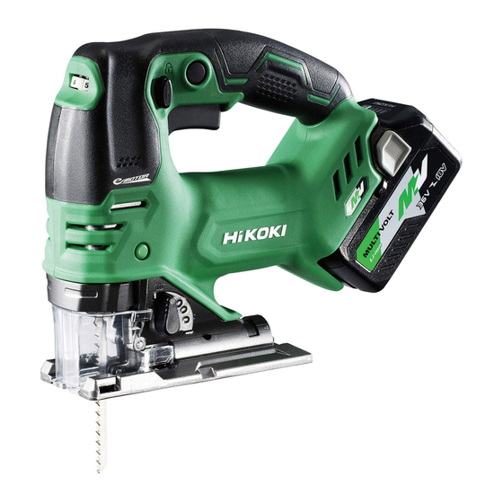
中文 符号 警告! 如下所示的符号用于本机。使用前请务必理解其含意。 为降低伤害风险,用户必须阅 空载转速 读使用说明书 /min 每分钟的振动次数 直流电 额定电压 警告 零件名称 1. 电动工具 锁定 开关 开关 锁定按钮 把手 转盘 铭牌 LED 灯 电池 电机 杆 内六角扳手 底座 刀片 底座盘 换档旋钮 导向 滚轮 图 3 2. 电池 ( 选购件 ) 3. -
Page 10: 标准附件
中文 规格 电动工具 型式 CJ36DA 电压 36 V 最大锯深 木材 160 mm 软钢 10 mm 不锈钢 3.2 mm 空载转速 800 - 3500 /min 冲程 26 mm 最小切割半径 25 mm BSL36A18 : 锂离子 36 V / 18 V 电池 * (2.5 Ah / 5.0 Ah 10 节) 重量... -
Page 11: 电池的拆卸/安装法
中文 用途 ○ 切割各类木材及钻孔切割 ○ 切割软钢板,铝板及铜板 ○ 切割合成树脂,如酚醛树脂及氯乙烯 ○ 切割薄而软的建筑材料 ○ 切割不锈钢板(使用 No. 97 锯片) 电池的拆卸/安装法 1. 电池的拆卸法 把手 请先紧抓住把手、然后再推压电池插销以拆下 拉出 电池 ( 参照图 6)。 插入 注意! 按 切勿使电池短路。 插销 2. 电池的安装法 电池 插入电池时请注意极性 ( 参照图 6)。 图 6 充电 使用电动工具之前,按下述方法将电池进行充电。... - Page 12 中文 3. 充电 将电池插入充电器后,充电指示灯将呈蓝色闪烁。 电池完全充电后,充电指示灯将持续点亮呈绿色。( 参照 表 2) (1) 充电指示灯的指示状态 根据充电器或可充电电池的情况,充电指示灯的显示如 表 2 所示。 表 2 充电指示灯的指示状态 点亮 0.5 秒钟。不点亮 闪烁 充电前 0.5 秒钟。 (熄灭 0.5 秒钟) 插入电源 ( 红 ) 点亮 0.5 秒钟。不点亮 1 秒 闪烁 钟。 (熄灭 1 秒钟) 电池电量低于...
- Page 13 中文 (2) 可充电电池温度和充电时间相关资料 温度和充电时间如表 3 所示。 表 3 充电器 UC18YSL3 电池类型 锂离子电池 电池可充电 0℃ - 50℃ 温度 14.4 充电电压 多电压 BSL14xx 系列 BSL18xx 系列 系列 电池 (4 节) (8 节) (5 节) (10 节) (10 节) 充电时 BSL1415S : 15 BSL1815S : 15 间(环...
-
Page 14: 作业之前
中文 注意! ○ 如果电池长时间放置在阳光直射的地方或者刚刚使用完毕时,电池会变 热。如果此时对电池充电,充电器的充电指示灯会点亮 0.3 秒钟,然后熄灭 0.3 秒钟(熄灭 0.3 秒钟) 。此时请等待电池冷却后再开始充电。 ○ 充电指示灯闪动 ( 闪动间隔为 0.2 秒钟 ) 时,请检查充电器的电池连接器内 是否有异物并加以清除。如没有异物,则可能是电池或充电器发生了故障。 请将其送往当地授权服务中心。 ○ 因内置的微电脑需要约 3 秒钟才能确认正用 UC18YSL3 充电的电池已被取出, 因此请等待 3 秒钟后再重新插入电池继续充电。如果在不到 3 秒内就插入电 池,则电池可能充电不正常。 作业之前 注意! 为避免发生严重事故,请确保开关处于关断位置,并取出电池。 勾脚 槽口 1. 检查工作区域环境。 检查工作区域,确保没有杂物且不杂乱。... - Page 15 中文 4. 更换锯片 注意! ○ 在更换锯片时,请务必关闭开关,从插座拔出插头。 ○ 柱塞移动时请勿触摸该杆。 ○ 使用后切勿立即触碰刀片。 金属很热,容易烫伤皮肤。 (1) 按照箭头所指示的方向拉动调校滑块。 (图 9 - I) (2) 拉动调校滑块的同时,插入锯片直至在锯片固定器端部外口卡住。 (图 9 - II) (3) 松开调校滑块。 (图 9 - III) 柱塞 锯片 导向滚轮 固定器 锯片固定器 导向滚轮 锯片 图 9- I 图 9- II 图...
- Page 16 中文 (2) 自动模式 自动模式自动选择每分钟 1400 至 3500 的速度,以适应工作负载并在关闭 开关之前一直保持该速度。根据工作负载不同,自动模式“A”会自动将锯 片运转速度更改为 1400 /min 或 3500 /min。这样可以在运转前和运转过程 中有效减少振动和噪音。 将拨盘调整为最适合任务条件和材料的模式和速度。 锯片运转速度 模式 拨盘 锯片运转速度 标准模式 1 - 5 800 - 3500 /min 未负载 : 1400 /min 自动模式 负载 : 3500 /min 使用自动模式时,振动频率可能达不到每分钟 3500,具体视工作类型等变量而 定。...
- Page 17 中文 8. 碎屑防护头 底座螺栓 底座 内六角扳手 在切割木质材料时使用碎屑防护头可减 少切割表面的碎屑。 注意! 务必关机并将电池与机身断开。 在切割木质材料时使用碎屑防护头可减 图 13 少切割表面的碎屑。 使用附带的内六角扳手拧紧底座下部的螺栓, 尽量向前移动移动底座。 (图 13) 将碎片防护头插到底座上的适当位置,并且完 全插入。 (图 14) 底座 9. 副底座(单独出售) 碎屑防 注意! 护头 锯片 务必关机并将电池与机身断开。 图 14 用于进行例如弧形和圆形等曲线切割。通过消 副底座 除 在底座后部和材料之间可能出现的钩丝,可以 很简单地完成任务。 底座 在将副底座钩在底座端部后, 将副底座插入到位。 若要拆下,请向上拉。...
- Page 18 中文 11. 准备工作台(图 17) 底座 木材 鉴于刀片会延伸超出材料下表面,因此在切割时 应将材料放在工作台上。 如果将方块用作工作台, 请选择水平地面以确保其确实稳定。不稳定工作台 刀片 工作台 会导致危险操作。 注意! 图 17 为了避免可能发生事故,请始终确保切割后剩余材 料部分牢固地固定或保持在原位。 12. 检查电池插入情况 警告! 如果在电源开关处于开 (ON) 位置时插入电池,电动工具会立即开始运行, 引发严重事故。 注意! 直至随着咔嗒一声电池锁定到位,否则,电池可能会意外地从工具中掉出, 对您或周围人造成伤害。 操作 警告! ● 切勿触摸运动部件。 ● 切勿在刀片转向上方或侧面的情况下操作曲线锯。 注意! ● 为了延长使用寿命,锂离子电池配有可停止输出的保护功能。 因此,如果 工具过载,电机可能会停下来。 然而,这并非故障,而是保护功能造成的 结果。在这种情况下,请释放工具的开关并消除过载原因。...
- Page 19 中文 1. 开关的操作 锁定解除按钮 锁住 (1) 锁定解除按钮 本工具配有锁定解除按钮。如要启动工具, 按下锁定解除按钮,然后按下扳机开关。 按 ( 图 18) 注意! 请勿固定锁定解除按钮。 此外,携带工具时,使手指远离扳机开关。 解锁 否则可能会在不经意间按下扳机开关,导 致意外事故。 (2) 搬钮开关 本工具配有控制各种速度的搬钮开关。通 开关 过按压和松开搬钮可将工具打开或关闭, 通过按压搬钮来调整至合适的电锯的速度 图 18 (从铭牌标注的最小速度至最大速度) ,向 下按时速度加大, 松开时速度减小。( 图 19) 此外,释放开关可激活断开,使刀片立即 停下来。 若要进行持续运转,请将开关拉动到位并 按下制动器。( 图 20) 开关 若要取消持续运转,请再一次将开关拉动...
- Page 20 中文 3. 灯警示信号 ( 图 22) 本产品具有旨在保护工具本身和电池的功能。 当触发任何安全保护功能时,任何 LED 灯均 会如表 4 所述闪烁。 在这种情况下,请按照纠正措施中所述说明 进行操作。 图 22 表 4 保护功能 LED 灯显示 正确步骤 开启 0.1 秒 / 关闭 0.1 秒 过载保护 去除过载原因 开启 0.5 秒 / 关闭 0.5 秒 让该工具和电池得到充分 温度保护...
- Page 21 中文 表 5 指示灯状态 电池剩余电量 点亮 ; 电池剩余电量超过 75% 点亮 ; 电池剩余电量为 50% - 75% 点亮 ; 电池剩余电量为 25% - 50% 点亮 ; 电池剩余电量不到 25% 闪烁 ; 电池剩余电量即将耗尽。请尽快对电池进行充电。 闪烁 ; 因高温暂停输出从电动工具中取下电池,让电池完全冷却。 闪烁 ; 因失败或故障暂停输出。 电池可能出现故障, 请与经销商联系。 环境温度和电池特性不同,则所显示的电池剩余电量也会有些许不同,以上 内容仅供参考。 注 : 请勿强烈撞击或破坏开关面板。否则可能会导致故障。...
- Page 22 中文 (3) 将导架穿过导底座上的导架孔,上紧 M5 螺栓。 (图 25) (4) 将轨道位置设为“0” 。 注 : 为 在 使 用 导 架 时 确 保 精 确 地 切 割 (图 26) ,总是将轨道位置设为“0” 。 2. 曲线切割 M5 螺栓 当切割一个小的弧形时,降低机器的喂 安装孔 料速度。如向机器的喂料速度过快,可 导架 能导致锯片损坏。 将轨道位置设为“0” 。 图...
- Page 23 中文 4. 切割金属材料(图 28) 转盘 3 - 4 油壶 (1) 调整速度。拨到刻度“3”与“4” 之间。 (2) 将轨道位置设置为“0”或图中 所示位置。 换档旋钮 注 : 图 28 总是使用适当的切割液(锭子油, 肥皂水等) 。当切割液不合适时, 将油酯涂在切割材料的背面。 5. 钻孔切割(图 29) (1) 使用内六角扳手松开附在底座上的 底座螺栓。 (第 21 页的图 24) (2) 将底座充分向前移动(第 21 页的 图 24)再次上紧底座螺栓。 (3) 将轨道位置设为“0”...
-
Page 24: 关于不锈钢板的切割
中文 (1) 使用内六角扳手松开附在底座上的底座螺栓, 内六角扳手 并将底座充分向前移动。 (图 31) 底座螺栓 底座 (2) 利用后表面上的 [ ] 符号,调整底座半圆片 的 刻 度( 从 0 度 到 45, 每 次 增 加 15 度 ) 。 (图 32) (3) 再次上紧 M5 螺栓。 (图 31) (4) 将轨道位置设为“0” - “III” 。 注... -
Page 25: 锯片的选择
中文 2. 将轨道位置设为“0” 注 : 切割时请使用切割液(油质切割液)以延长锯片的使用寿命。 锯片的选择 ○ 附件锯片 为确保最高的作业效率及最好的作业结果,选择最适合切割材料的类型与厚 度的适当的锯片是十分重要的。每片锯片的脊部附近刻有锯片号。参考第 32 页的表 6,选择适当的锯片。 卡住内六角扳手 可以卡住底座上的内六角扳手。 (参看图 34) 底座 内六角扳手 图 34 连接到清洁器 通过集尘器(单独出售)和附加器(单独出售)与 内六角扳手 清洁器(单独出售)相连接, 能够收集大多数尘屑。 底座 底座螺栓 (1) 使用内六角扳手松开附在底座上的底座螺栓。 (图 35) (2) 将底座充分向前移动再次上紧底座螺栓 (图 35) 。 图 35... -
Page 26: Usb设备的充电方法
中文 (3) 安装盖片。( 第 17 页的图 16) (4) 通过附加器连接上集尘附加器。 (图 36) (5) 连接附加器与清洁器的接头。 (图 36) (6) 将清洁器插入底座的后孔直至勾脚插入 附加器 接头 槽口。 (图 37) (7) 按住勾脚以取下集尘附加器。 底座 集尘器附加器 清洁器 图 36 槽口 勾脚 后孔 图 37 USB设备的充电方法 警告! ○ 使用之前请检查 USB 连接线缆是否有破损或损坏。 使用有破损或损坏的... -
Page 27: 维护和检查
中文 (2) 连接 USB 线缆。( 图 39) 拔下橡胶盖并将市售的 USB 线 橡胶盖 缆(匹配充电的设备)紧紧插 入 USB 端口。 USB 端口 USB 线 图 39 (3) 充电完成时 ○ 检查 USB 设备以检验充电状态。 橡胶盖 ○ 从插座中拔下电源线。( 图 40) ○ 用橡胶盖盖住 USB 端口。 USB 端口 USB 线 图... - Page 28 不时用一滴油润滑滚轮导轨和刀架。 这会延长滚轮的使用寿命。 7. 电力耗尽的电池的处理方法 警告! 请勿将电力耗尽的电池丢弃。如果焚烧电池,可能会引起爆炸。该电池可回 收利用。根据各国家和地区的法令法规,将电力耗尽的电池丢弃到城市垃圾 中属于违法行为。请向当地的固体废弃物负责人员咨询具体回收事宜或妥善 的处理方法。 8. 收藏 电动工具应收藏于温度低于 40℃和小孩拿不到的地方。 注 : 存放锂离子电池 在存放前请确保电池已完全充电。 电池在低电量的状态下长时间存放 (3 个月或更长 ),可能会导致电池性能劣 化,使用时间明显减少或无法进行充电。 但是,即使是使用时间明显减少的电池,通过反复充电和使用 2 ~ 5 次,有 时也可恢复使用时间。 若反复充电和使用后电池的使用时间仍非常短,请认作为电池已达到了使用 寿命并更换新的电池。 注意! 在操作和维修电动工具时,必须遵守贵国制定的安全的有关规则和标准。 关于 HiKOKI 牌无线电动工具的重要通知 : 请确保始终使用我们指定的正版电池。如果使用我们指定以外的电池,或对电 池进行拆卸和改动(例如拆卸和更换电池组件或其他内部部件) ,那么我们无 法保证我们无线电动工具的安全性和使用性能。...
-
Page 29: 故障排除
中文 故障排除 如果工具操作不正常,请使用下表中的检查步骤。如果未能解决问题,请向经 销商或 HiKOKI 公司授权服务中心咨询。 1. 电动 故障现象 可能原因 纠正方法 工具不运转 电池电量耗尽 给电池充电。 电池没装好。 将电池推入,直至听到咔嗒 声为止。 工具突然停下来 工具负载过重 解决导致负载过重的问题。 在操作过程中,减轻所施加 的压力。 电池或工具过热 使工具和电池彻底冷却。 刀片 连接部分形状不匹配 使用适合刀片 - 无法连接 (参见“选择附件” ) - 脱落 杆已打开。 将杆闭合。 刀架内部有异物。 清除异物。 无法拉动开关 锁定按钮已推入。 释放锁定按钮。... - Page 30 即使电池完全充 电池的使用寿命已耗尽。 请更换新电池。 电,电池的使用 寿命也会逐渐缩 短。 电池的充电时间 电池、充电器或周围环境 请在室内或温暖的环境中充电。 较长。 的温度过低。 充电器的排气孔堵塞,导 请勿堵塞排气孔。 致其内部部件过热。 冷却扇未运转。 请联系 HiKOKI 授权服务中心进 行维修。 USB 电源灯熄灭, 电池剩余电量低。 用电量充足电池替换它。 USB 设备停止充 将充电器的电源插头插入电插座 电。 中。 即使 USB 设备充 USB 电源灯点亮呈绿色, 这种情况不属于故障。 电完毕,USB 电 提示可进行 USB 充电。 源灯也不熄灭。...
- Page 31 中文 现象 可能的原因 解决办法 USB 设备在中途 使用电池作为电源对 USB 这种情况不属于故障。 暂停充电。 设备进行充电时,充电器 充电器与电源间存在差异时, 插入电插座。 USB 将暂停充电约 5 秒钟。 使用电源插座作为电源对 USB 设备进行充电时,电 池插入充电器。 电池和 USB 设备 电池已完全充电。 这种情况不属于故障。 同时充电时,USB 检查电池是否已充电完成时,充 设备将在中途暂 电器将暂停 USB 充电约 5 秒钟。 停充电。 电池和 USB 设备 电池剩余电量已不足。 这种情况不属于故障。 同时充电时,USB 电池电量达到一定程度时,USB 设备将无法开始...
- Page 32 中文 表 6 适用锯片列表 切 锯片 No. 1 割 ( 超长 ) 材 材料 材料厚度 (mm) 料 性质 低于 10 ~ 低于 10 ~ 5 ~ 10 ~ 一般木材 木 材 5 ~ 低于 5 ~ 3 ~ 夹板 3 ~ 低于...
-
Page 33: 选择附件
中文 选择附件 有关详细信息请联系HiKOKI授权服务中心。 BSL36A18 BSL36B18 329897 UC18YSL3 (14.4 V - 18 V) BSL36C18 产品编号 321878 锯片 879336 879337 879338 879339 879340 879341 879357 963400 产品编号 : 944458 内六角扳手 产品编号 : 879391 导架 产品编号 : 338997 碎屑防护头 产品编号 : 370492 集尘附加器... - Page 34 中文 碎屑盖 产品编号 : 338996 塑料箱 产品编号 : 337108 内托盘 产品编号 : 375861...
-
Page 35: General Power Tool Safety Warnings
English Contents GENERAL POWER TOOL SAFETY WARNINGS ........35 JIG SAW SAFETY WARNINGS ..............38 PRECAUTIONS FOR CORDLESS JIG SAW ..........38 CAUTION ON LITHIUM-ION BATTERY ............40 REGARDING LITHIUM-ION BATTERY TRANSPORTATION ...... 42 USB DEVICE CONNECTION PRECAUTIONS ..........42 SYMBOLS .................... - Page 36 English Keep children and bystanders away while operating a power tool. Distractions can cause you to lose control. Electrical safety a) Power tool plugs must match the outlet. Never modify the plug in any way. Do not use any adapter plugs with earthed (grounded) power tools. Unmodifi...
- Page 37 English g) If devices are provided for the connection of dust extraction and collection facilities, ensure these are connected and properly used. Use of dust collection can reduce dust-related hazards. h) Do not let familiarity gained from frequent use of tools allow you to become complacent and ignore tool safety principles.
-
Page 38: Jig Saw Safety Warnings
English When battery pack is not in use, keep it away from other metal objects, like paper clips, coins, keys, nails, screws or other small metal objects, that can make a connection from one terminal to another. Shorting the battery terminals together may cause burns or a fi re. d) Under abusive conditions, liquid may be ejected from the battery;... - Page 39 English Do not allow foreign matter to enter the hole for connecting the rechargeable battery. Never disassemble the rechargeable battery and charger. Never short-circuit the rechargeable battery. Short-circuiting the battery will cause a great electric current and overheat. It results in burn or damage to the battery. Do not dispose of the battery in fi...
-
Page 40: Caution On Lithium-Ion Battery
English 18. During use, do not touch the metal portion of the tool. 19. Do not use the product if the tool or the battery terminals (battery mount) are deformed. Installing the battery could cause a short circuit that could result in smoke emission or ignition. - Page 41 English If the battery charging fails to complete even when a specifi ed recharging time has elapsed, immediately stop further recharging. Do not put or subject the battery to high temperatures or high pressure such as into a microwave oven, dryer, or high pressure container. Keep away from fi...
-
Page 42: Regarding Lithium-Ion Battery Transportation
English REGARDING LITHIUM-ION BATTERY TRANSPORTATION When transporting a lithium-ion battery, please observe the following precautions. WARNING Notify the transporting company that a package contains a lithium-ion battery, inform the company of its power output and follow the instructions of the transportation company when arranging transport. -
Page 43: Name Of Parts
English NAME OF PARTS 1. POWER TOOL Stopper Switch Lock-off button Handle Dial Name plate LED light Battery Motor Lever Hexagonal bar wrench Base Blade Base plate Change knob Guide roller Fig. 3 2. Battery (Optional accessories) 3. Battery Charger (Optional accessories) Battery cover Charge indicator lamp Cord... -
Page 44: Specifications
English SPECIFICATIONS POWER TOOL Model CJ36DA Voltage 36 V Max. Cutting Depth Wood 160 mm Mild Steel 10 mm Stainless steel 3.2 mm No-load speed 800 – 3500 /min Stroke 26 mm Min. Cutting Radius 25 mm BSL36A18: Li-ion 36 V / 18 V Battery* (2.5 Ah / 5.0 Ah 10 cells) Weight... -
Page 45: Applications
English APPLICATIONS ○ Cutting various lumber and pocket cutting ○ Cutting mild steel plate, aluminum plate, and copper plate ○ Cutting synthetic resins, such as phenol resin and vinyl chloride ○ Cutting thin and soft construction materials ○ Cutting stainless steel plate (with No. 97 blade) BATTERY REMOVAL / INSTALLATION Battery removal Hold the handle tightly and push the battery latches to remove the battery (see Fig. - Page 46 English Charging When inserting a battery in the charger, the charge indicator lamp will blink in blue. When the battery becomes fully recharged, the charge indicator lamp will light up in green. (See Table 2) Charge indicator lamp indication The indications of the charge indicator lamp will be as shown in Table 2, according to the condition of the charger or the rechargeable battery.
- Page 47 English Regarding the temperatures and charging time of the rechargeable battery The temperatures and charging time will become as shown in Table 3. Table 3 Charger UC18YSL3 Type of battery Li-ion Temperatures at which the 0 oC – 50 oC battery can be recharged Charging...
-
Page 48: Prior To Operation
English How to make the batteries perform longer. Recharge the batteries before they become completely exhausted. When you feel that the power of the tool becomes weaker, stop using the tool and recharge its battery. If you continue to use the tool and exhaust the electric current, the battery may be damaged and its life will become shorter. - Page 49 English Changing blades CAUTION ○ Be sure to switch power OFF and disconnect the battery from the body when changing blades. ○ Do not touch the lever when plunger is moving. ○ Never touch the blade immediately after use. The metal is hot and can easily burn your skin.
- Page 50 English <About Operation mode> The tool is equipped with two modes: “Standard Mode” and “AUTO Mode”. Standard Mode You can change the blade operating speed between 800 to 3500 /min by adjusting the dial from “1” to “5”. AUTO Mode AUTO Mode automatically selects a speed between 1400 and 3500 /min to suit the operating load and maintains that speed until the switch is turned off...
- Page 51 English Using the provided Hexagonal bar wrench, tighten Hexagonal Base bolt Base the bolts in the lower area of the base, moving the bar wrench base as far forward as possible. (See Fig. 13) Insert the splinter guard in the space on the base, and push it completely.
-
Page 52: Operation
English 11. Prepare a work bench (Fig. 17) Base Lumber Since the blade will extend beyond the lower surface of the material, place the material on a work bench when cutting. If a square block is utilized as a work bench, select level ground Work bench Blade to ensure it is properly stabilized. - Page 53 English Switch operation Lock-off button Lock Lock-off button The tool is equipped with a lock-off button.To start the tool, press the lock-off button and then squeeze the trigger switch. (Fig. 18) Push CAUTION Do not fi x and secure the lock-off button. Besides, keep your fi...
- Page 54 English LED light warning signals (Fig. 22) This product features functions that are designed to protect the tool itself as well as the battery. When any of the safeguard functions are triggered, any of the LED light will blink as described in Table 4. In this case, follow the instructions described under corrective action.
-
Page 55: Cutting
English Table 5 State of lamp Battery Remaining Power Lights ; The battery remaining power is over 75% Lights ; The battery remaining power is 50% – 75%. Lights ; The battery remaining power is 25% – 50%. Lights ; The battery remaining power is less than 25% Blinks ;... - Page 56 English Attach the guide by passing it through the attachment hole on the base and tighten the M5 bolt. (Fig. 25) Set the orbital position to “0”. NOTE To ensure accurate cutting when using the guide (Fig. 26), always set the orbital position to “0”.
- Page 57 English Cutting metallic materials (Fig. 28) 3 - 4 Dial Adjust the speed dial between scales “3” Oiler and “4”. Set the orbital position to “0” or to the position indicated in the fi gure. NOTE Change knob Always use an appropriate cutting fl uid (spindle oil, soapy water, etc.).
-
Page 58: Concerning Cutting Of Stainless Steel Plates
English Loosen the base bolt by hexagonal bar wrench Hexagonal bar wrench attached on base and move the base fully forward. Base Base bolt (Fig. 31) Align the scale (from 0 degrees to 45 degrees by 15-degree increments) of the semi-circular part of the base with the [ ] mark on the gear cover. -
Page 59: Selection Of Blades
English Set the orbital position to “0” NOTE When cutting use cutting fl uid (oil base cutting fl uid) to prolong the blade’s service life. SELECTION OF BLADES ○ Accessory blades To ensure maximum operating effi ciency and results, it is very important to select the appropriate blade best suited to the type and thickness of the material to be cut. -
Page 60: How To Recharge Usb Device
English Attach the chip cover. (Fig. 16 on page 51) Connect the dust collection adapter with adapter. (Fig. 36) Connect the adapter with the nose of Adapter cleaner. (Fig. 36) Nose Insert dust collection adapter into the rear hole of the base until the hook catches in the notch. -
Page 61: Maintenance And Inspection
English Connect the USB cable. (Fig. 39) Pull back the rubber cover and fi rmly plug in a commercially available USB Rubber cover cable (appropriate to the device being charged) into the USB port. USB port When charging is completed USB cable ○... - Page 62 In the operation and maintenance of power tools, the safety regulations and standards prescribed in each country must be observed. Important notice on the batteries for the HiKOKI cordless power tools Please always use one of our designated genuine batteries. We cannot guarantee the safety and performance of our cordless power tool when used with batteries other than these designated by us, or when the battery is disassembled and modifi...
-
Page 63: Troubleshooting
English TROUBLESHOOTING Use the inspections in the table below if the tool does not operate normally. If this does not remedy the problem, consult your dealer or the HiKOKI Authorized Service Center. Power tool Symptom Possible cause Remedy Tool doesn’t run No remaining battery power Charge the battery. - Page 64 The charger’s vents are blocked, Avoid blocking the vents. causing its internal components to overheat. The cooling fan is not running. Contact a HiKOKI Authorized Service Center for repairs.
- Page 65 English Symptom Possible cause Remedy The USB power lamp The battery’s capacity has Replace the battery with one that has switched off and become low. has capacity remaining. the USB device has Plug the charger’s power plug into stopped charging. an electric socket.
- Page 66 English Table 6 List of appropriate blades No. 1 Blade (Super No. 11 No. 12 No. 15 No. 16 No. 21 No. 22 No. 41 No. 97 Material to Long) be cut Material quality Thickness of material (mm) General Below 10 ∼...
-
Page 67: Selecting Accessories
English SELECTING ACCESSORIES For details contact HiKOKI Authorized Service Center. BSL36A18 BSL36B18 UC18YSL3 (14.4 V – 18 V) 329897 BSL36C18 Part Number 321878 Blades 879336 879337 879338 879339 879340 879341 879357 963400 Hexagonal bar Part Number: 944458 wrench Guide Part Number: 879391... - Page 68 English Chip cover Part Number: 338996 Case Part Number: 337108 Inner tray Part Number: 375861...
- Page 72 服务中心 高壹工机商业(上海)有限公司 上海市闵行区浦江工业园区三鲁路3585号7幢3楼 制造商 广东高壹工机有限公司 广东省广州市番禺区化龙镇工业路富裕围工业村 编号:C99735421 G 发行日期:2019年 7月 中国印刷...
Need help?
Do you have a question about the CJ 36DA and is the answer not in the manual?
Questions and answers