
Related Manuals for Atlas Copco LF 2


Summary of Contents for Atlas Copco LF 2
- Page 1 Atlas Copco Industrial aluminium piston compressor LF 2, LF 3, LF 5, LF 7, LF 10 Instruction book...
- Page 3 Atlas Copco Instruction aluminium pistion compressors LF 2, LF 3, LF 5, LF 7, LF 10 Instruction book Original instructions Copyright Notice Any unauthorized use or copying of the contents or any part thereof is prohibited. This applies in particular to trademarks, model denominations, part numbers and drawings.
-
Page 4: Table Of Contents
Instruction book Table of contents Safety precautions ........................4 Safety icons ........................4 Safety precautions, general ....................4 Safety precautions during installation ................4 Safety precautions during operation ................. 6 Safety precautions during maintenance or repair ............. 7 General description ........................9 General description ...................... - Page 5 Instruction book Storage after installation ....................47 Maintenance ..........................49 Petrol engine maintenance ....................49 Preventive maintenance schedule .................. 49 Service kits ........................50 Disposal of used material ....................50 Servicing and adjustment procedures ................51 Unloader or check valve ....................51 Valves ..........................
-
Page 6: Safety Precautions
Instruction book Safety precautions Safety icons Explanation Danger for life Warning Important note Safety precautions, general General Precautions 1. The operator must employ safe working practices and observe all related work safety requirements and regulations. 2. If any of the following statements does not comply with the applicable legislation, the stricter of the two shall apply. - Page 7 Instruction book Precautions during installation 1. The dryer must only be lifted using suitable equipment and in accordance with the applicable safety regulations. Loose or pivoting parts must be securely fastened before lifting. It is strictly forbidden to dwell or stay in the risk zone under a lifted load. Lifting acceleration and deceleration must be kept within safe limits.
-
Page 8: Safety Precautions During Operation
Instruction book Safety precautions during operation All responsibility for any damage or injury resulting from neglecting these precautions, or non-observance of the normal precaution and care required for installation, operation, maintenance and repair, even if not expressly stated, will be disclaimed by the manufacturer. Precautions during operation 1. -
Page 9: Safety Precautions During Maintenance Or Repair
Instruction book Safety precautions during maintenance or repair All responsibility for any damage or injury resulting from neglecting these precautions, or non-observance of the normal precaution and care required for installation, operation, maintenance and repair, even if not expressly stated, will be disclaimed by the manufacturer. Precautions during maintenance or repair 1. - Page 10 Instruction book Also consult following safety precautions: Safety precautions during installation and Safety precautions during operation. These precautions apply to machinery processing or consuming air or inert gas. Processing of any other gas requires additional safety precautions typical to the application which are not included herein.
-
Page 11: General Description
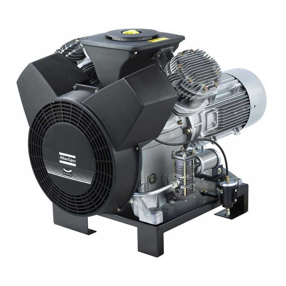
Instruction book General description General description Introduction LF are air-cooled, single-stage, two cylinder piston compressors delivering oil-free air. They are built for effective working pressure up to 10 bar. Compressor block with unloading valve Power Pack 2920 7090 00... - Page 12 Instruction book Power Pack with unloading valve Base mounted 2920 7090 00...
- Page 13 Instruction book Tank- mounted, LF2 up to LF5, horizontal receiver Tank mounted horizontal receiver 2920 7090 00...
- Page 14 Instruction book Tank- mounted, Full-Future unit, 475 l receiver LF Trolley Petrol/Electric Description Reference Air filter Air receiver Air outlet valve Check valve Condensate drain valve Oil drain plug Filler cap Air pressure gauge 2920 7090 00...
- Page 15 Instruction book Description Reference Motor Air pressure switch Electric motor Petrol engine Hourmeter, running time Pulsation damper Pilot valve On/off switch On/off switch dryer Oil sight glass Safety valve Unloader Blow-off silencer Loading solenoid valve Description Reference Cover Air inlet silencer Crankcase Cooling pipe Left cylinder...
-
Page 16: Operation
For LF 2 up to LF 3: The Power pack mounted on a horizontal or vertical air receiver (AR) with air outlet valve (AV), pressure gauge (Gp), safety valve (SV), air pressure switch with an on/off button (MDR) and condensate drain valve (Dm). -
Page 17: Air Flow
Instruction book LF 2-3 on 90 and 250 receiver CD adsorption dryer For PP-BM-TM-FF versions Heavy duty air inlet filter Not available for LF Oil level switch Wheelset for 90/250 receiver Receiver wheel set Power supply cable with red CEE 3-pole plug 16A L = 3 mtr... - Page 18 Instruction book Air flow and regulating system with DOL starter 2920 7090 00...
- Page 19 Instruction book Air flow and regulating system with Y/D starter 2920 7090 00...
- Page 20 Instruction book Air flow and regulating system of trolley 2920 7090 00...
- Page 21 Instruction book Full-Feature Air flow and regulating system, Full-Feature References on flow diagrams Description Reference Air filter Air receiver Air outlet valve Air outlet valves AV/AV2 Check valve Condensate drain valve Oil filter cap Air pressure gauge Motor Air pressure switch Pulsation damper On/off switch Pilot valve...
-
Page 22: Regulating System
Electrical cubicle Plunger Spring Pressure regulator Refrigerant dryer Regulating system LF 2 up to LF 10 with DOL starter The regulating system includes: Check valve (CV) Air pressure switch (MDR) with pressure release valve (6) and on/off button (S1). - Page 23 Instruction book Electric cubicle Air pressure switch (MDR) On/off switch (S1) Solenoid valve (Y1) Unloader (UA) with integrated check valve Operation Air pressure switch (MDR) opens and closes its contacts at pre-set pressures. During loaded operation, the contacts are closed: the motor is running and solenoid valve (Y1) is energized preventing the compressed air from flowing to unloader (UA).
-
Page 24: Installation
L E / L F 5 0 4 2 5 2 6 8 7 9820 2239 01/08 3 6 5 6 1 5 5 3 3 2 7 9 6 8 7 81448D LF 2 up to LF 5, Power Pack 2920 7090 00... - Page 25 Instruction book LE/LT/LF 7-10 For Dismantling Air inlet Compressor Air Inlet VIEW E 10 p9 M8(4x) VIEW E Cooling Air Inlet Ø 49,5 Compressor Air Outlet G1/2" VIEW H Cooling Air inlet VIEW H Compressor Air Outlet G 1/2" Net Mass Net Mass Power Type Block (Kg)
- Page 26 Cooling Air inlet Cooling Air inlet Compressed Air oulet G 1/2" Type Net Mass (Kg) LE/LF 2 LE/LF 3 LE/LF 5 LT 2 9820 2239 42/06 LT 3 81452D LT 5 LF 2 up to LF 5,Base-mounted 2920 7090 00...
- Page 27 Instruction book For dismantling BM LE/LT/LF 7-10 YD Air filter Compressor Air inlet Cooling Air outlet Motor cooling Compressor cooling Air inlet Air inlet Compressed Air outlet G1/2" Type Net mass (Kg) 9820 2239 43/05 LE/LT/LF 7 81453D LE/LT/LF 10 LE 10 (60 Hz) LF 7 up to LF 10, Base-mounted 2920 7090 00...
- Page 28 81454D LE/LT/LF 1254 12.5 191.5 229.5 85.5 LE/LT/LF 1254 12.5 191.5 229.5 85.5 LE/LT/LF 1180 1395 42.5 191.5 296.5 123.5 LE/LT/LF 1180 1395 42.5 191.5 296.5 123.5 LF 2 up to LF 10, Pack with silencing hood 2920 7090 00...
- Page 29 Cooling air inlet Compressed air outlet G 1/2" Slot Hole 15x25 (4x) Manual drain G 1/4" Type Receiver (L) Netmass (Kg) A LE/LF 9820 2239 21/07 81455D 533 279 LF 2 up to LF 3, Tank-mounted, receiver 90 l 2920 7090 00...
- Page 30 1 4 9 5 0 4 2 5 2 1 5 0 81457D Type Receiver (L) Net Mass (Kg) LE 5 LT 5 1926 1261 LF 5 LF 2 up to LF 5, Tank-mounted horizontal receiver 250/475l 2920 7090 00...
- Page 31 Instruction book LE/LT/LF 7-10 FOR DISMANTLING AIR FILTER COMPRESSOR AIR INLET COMPRESSOR AIR INLET COOLING AIR OUTLET COMPRESSOR MOTOR COOLING COOLING AIR INLET AIR INLET Ø L COMPRESSED AIR OUTLET G 1/2" SLOT HOLE MANUAL DRAIN 15x25 (4x) OUTLET G 1/4" F max.
- Page 32 Dryer cooling air outlet Dryer cooling air inlet Type Net Mass LE/LF 2 171 kg 9820 4496 00/01 1072 LE/LF 3 175 kg 81458D 177 kg 1082 LF 2 up to LF 3, Tank-mounted Full-Feature, receiver 250 l 2920 7090 00...
- Page 33 Instruction book 1398 For dismantling air filter Compressor Air inlet Cooling air outlet Cooling air inlet Dryed compressed air outlet G 1/2" Compressed air outlet G 1/2" 476 5 Manual drain outlet G 1/4" 1888 Dryer cooling air outlet Dryer cooling air inlet Type Net Mass 225 kg...
- Page 34 LF/LE 1161 1694 1852 LF/LE 1340 1872 1926 1025 1161 1694 1852 1340 1872 1926 1025 LF/LE 1076 1603 1034 1076 1603 1034 9820 2239 24/08 81460D LF 2 up to LF 5, Tank-mounted with silencing hood 2920 7090 00...
- Page 35 Instruction book 9820 2239 26/09 81461D LF 7 up to LF 10, Tank-mounted with silencing hood 2920 7090 00...
- Page 36 Instruction book 40 (For dismantling air filter) Inlet 311,5 1131 Compressed 1569 air outlet RECEIVER NET MASS TYPE (lit.) (Kg) LE/LT/LF 2 x 10 ltr. LE/LT/LF 2 x 10 ltr. LE/LT 2 x 10 ltr. 1024 9820 2239 71/07 81462D LF Trolley with electrical motor 2920 7090 00...
- Page 37 Instruction book 9820 2239 91/05 81463D LF Trolley with Petrol Engine References of figures on dimension drawings. Reference Designation Air inlet Hole, 15 x 25 (4X) Cooling air inlet Net mass Compressed air outlet, G1/2 2920 7090 00...
-
Page 38: Installation Instruction
Instruction book Reference Designation Manual condensate drain Hole, 15 x 25 (3X) Receiver Cooling air inlet Motor cooling air inlet Compressed air outlet Compressor cooling air and air inlet For dismantling air filter Compressor air outlet with flexible (2 meters) Electric cable entry (on rear side) Air outlet Manual condensate drain... - Page 39 Instruction book Installation proposal for tank-mounted unit (250/475 l receiver) 2920 7090 00...
- Page 40 Instruction book Installation proposal for base-mounted unit with optional silencing hood 2920 7090 00...
- Page 41 Instruction book Installation proposal for tank mounted compressors with silencing hood References of figures on installation drawings. Reference Description Cooling air outlet Compressor air and cooling air inlet Install the compressor horizontally, in a cool but frost-free and well-ventilated room. LF can operate with any angular deviation, in any direction.
-
Page 42: Electrical Connections
Instruction book Electrical Connections Warning The electrical connection must be carried out by an electrician and corresponds to the local codes. The indications on the motor data plate must correspond to the power supply voltage and frequency. The installation must include an isolating switch in the power line near to the unit and be protected against short-circuits by fuses for each phase refer section Overload relays and fuses or Cable sizes. -
Page 43: Settings Of Overload Relay And Fuses
Instruction book Reference Description Hourmeter, running hours Terminal board On/off switch Electrical diagram with direct-on-line starter Settings of overload relay and fuses Overload Relay Settings - compressor fuses with DOL starter 50Hz Type Voltage (V) Overload relay (A) Fuses (A) 230 MONO 230 MONO 2920 7090 00... - Page 44 Instruction book Type Voltage (V) Overload relay (A) Fuses (A) LF10 LF10 60Hz Type Voltage (V) Overload relay (A) Fuses (A) 115 MONO 230 MONO 230 MONO 230 MONO LF10 LF10 LF10 2920 7090 00...
- Page 45 Instruction book Settings of overload relay and fuses of compressors with Y-D starter 50Hz Type Voltage (V) Overload relay (A) Fuses (A) LF10 LF10 LF10 LF10 LF10 LF10 60Hz Type Voltage (V) Overload relay (A) Fuses (A) 10.5 LF10 LF10 10.5 LF10 2920 7090 00...
-
Page 46: Cable Sizes
Instruction book Cable sizes Starter Cable size mm² LF 2 and LF 3 LF 5 and LF 7 LF 7 LF 10 Pictographs Reference Designation Temperature Pressure Warning: voltage Switch off voltage and depressurize before maintenance or repair Read Instruction book before starting... -
Page 47: Operating Instructions
Instruction book Operating Instructions Initial start –up 1. For Tank-mounted and base mounted units, remove the RED transport brackets from underneath the compressor. 2. Check the electrical installation, which must be in accordance with the instructions given in Electrical connection. 3. - Page 48 Instruction book To ensure optimum operational efficiency, do not use dryer on/switch repeatedly within a short time period. Wait at least 5 minutes to start the dryer again after stopping to allow pressure equalization. 4. Open the air outlet valve (AV). Regularly drain condensate LF Trolley with electrical motor 1.
-
Page 49: Stopping
Instruction book 3. Start the engine, consult the engine "Owner's manual". 4. Attach the air lines to the air outlets. 5. Open the outlet valves (AV1/2). 6. Set pilot valve (RV) in the load position by turning the red handle 90 degrees. See section Adjustment of pilot valve. - Page 50 If the machine is stored in packing, put some vapor corrosion inhibitor (VCI) paper into the packing. If the machine is stored for 1 year or more, rotate the bearings once a month to change the position of the roller balls in the bearings. Consult Atlas Copco Service. 2920 7090 00...
-
Page 51: Maintenance
Instruction book Maintenance Petrol engine maintenance Consult the engine "Owner's manual". Preventive maintenance schedule The schedule contains a summary of the maintenance instructions. Read the respective section before taking maintenance measures. When servicing, replace all disengaged packing components, e.g. gaskets, O-rings, washers. -
Page 52: Service Kits
Service kits Service kits are available, offering the benefits of genuine Atlas Copco parts while keeping the maintenance budget low. The kits comprise all parts needed for servicing. Consult the Parts list for the contents of all kits. -
Page 53: Servicing And Adjustment Procedures
Dirt, condensate and oxidation influence the proper operation of the valve. Depending on the environmental and working conditions (ambient temperature, working pressure, load cycle, oil type), the local Atlas Copco customer center or authorized distributor may overrule the maintenance schedule (consult Atlas Copco). - Page 54 Instruction book It is highly recommended to replace the valve discs, O-rings and gaskets if disassembling the cylinder heads. Cylinder heads, low pressure variants 10 9 13 1 Reference Description Suction disc Seat O-ring Delivery disc Valve guard Spring Head Bolt Washer Stud...
-
Page 55: Air Filter
Instruction book Replacement of valve discs Operation sequence Remove the fan guard, unscrew the cap and remove the cover, air filter and cover of the air inlet silencer (1). Disconnect cylinder head cover (12) from the inlet and outlet pipe flanges. Remove cylinder head cover. ... - Page 56 Instruction book Name Air pressure switch Solenoid valve Pressure release valve Adjusting screw, stopping pressure Adjusting screw, pressure difference Function The adjustment of the maximum or stopping pressure of the compressor is effected by means of the air pressure switch. The switch also controls the pressure difference between the maximum pressure (stopping pressure) and the pressure at which compression is resumed (starting pressure).
-
Page 57: Adjustment Mdr3 Pressure Switch
Instruction book Example: Stopping pressure: 7 bar(e) Starting pressure: adjustable between 3 and 5.7 bar(e) Adjustment MDR3 pressure switch Views of air pressure switch MDR3 with ON/OFF switch This pressure switch has a cover with rotary knob (4) for manual On/Off (Auto/Off). Reference Description Dial, overload relay... -
Page 58: Adjustment Of Pilot Valve On Trolley
Instruction book Pressure difference diagram, MDR3/11 (10 bar units) Example: Stopping pressure: 7 bar(e) Starting pressure: adjustable between 3 and 5.7 bar(e) Name Starting pressure - bar(e) Stopping pressure - bar(e) Adjustment of pilot valve on Trolley The adjustment of the maximum or unloading pressure of the compressor is effected by means of pilot valve (RV) The valve also controls the difference between the preset maximum pressure and that at which compression is resumed. -
Page 59: Safety Valve
Instruction book Description Control air to unloader Vent hole Unloading handle Pressure adjusting screw Nuts Shims Unload mechanism The pilot valve is equipped with a hand-operated unload mechanism: by turning the red handle (1) 90 degrees, the plunger of the valve will be lifted, releasing the spring force. The air pressure from pulsation dampers will force down unloader plunger (8) and the compressor will run unloaded. - Page 60 Instruction book Testing on Trolley Close the air outlet valves depressurize and disconnect the hoses from the valves. Loosen the red handle of the pilot valve (1) and the two nuts (3) Open outlet valve (AV1) a fraction. Start the compressor. Gradually turn adjusting screw (2) clockwise while checking pressure gauge (Gp).
-
Page 61: Problem Solving
Instruction book Problem solving Condition Fault Remedy Insufficient air pressure Air leak Check and correct as necessary Air filter choked Replace filter Air pressure switch incorrectly Adjust switch Air consumption exceeds Check equipment connected maximum output of compressor Damaged valve Inspect valves and replace parts where necessary Unloader malfunctioning... - Page 62 Blow-off silencer choked Replace Ambient temperature too high Improve ventilation of room Motor stops and starts too See "Too frequent starting/too frequently short operating periods" Overcurrent due to motor or Consult Atlas Copco compressor failure 2920 7090 00...
-
Page 63: Technical Data
Maximum working pressure bar(e) See below Only applicable for Full Feature variants. (with refrigerant dryer) Minimum ambient air temperature °C Compressor data 50 Hz (10 bar) Compressor LF 2 LF 3 LF 5 LF 7 LF 10 type Maximum bar(e) working... - Page 64 Instruction book Compressor LF 2 LF 3 LF 5 LF 7 LF 10 type Motor shaft r/min 1500 1500 1500 1500 1500 speed Free air 14.4 delivery (Note Opening bar(e) pressure of safety valve Maximum sound pressure level (Note 2)
- Page 65 Instruction book Compressor LF 2 LF 3 LF 5 LF 7 LF 10 type Opening bar(e) pressure of safety valve Maximum sound pressure level (Note 2) - Tank- dB(A) mounted - Tank- dB(A) mounted with hood - Base- dB(A) mounted with...
-
Page 66: Instructions For Use
Instruction book Instructions for use Air receiver (tank-mounted units) Corrosion must be prevented: depending on the conditions of use, condensate may accumulate inside the tank and must be drained every day. This may be done manually, by opening the drain valve, or by means of the automatic drain, if fitted to the tank. Nevertheless, a weekly check of correct functioning of the automatic valve is needed. -
Page 67: Pressure Equipment Directive (Ped)
Instruction book Pressure Equipment Directive (PED) Components subject to the 97/23/EC Pressure Equipment Directive The following table contains the necessary information for the inspection of all pressure equipment of category II and higher according to the Pressure Equipment Directive 97/23/EC and all pressure equipment according to the Simple Pressure Vessel Directive 2009/105/EC. -
Page 68: Declaration Of Conformity
Instruction book Declaration of conformity EC DECLARATION OF CONFORMITY We, Atlas Copco Airpower n.v., declare under our sole responsibility, that the product Machine name Machine type Serial number Which falls under the provisions of article 12.2 of the EC Directive 2006/42/EC on the approximation of the laws of the Member States relating to machinery, is in conformity with the relevant Essential Health and Safety Requirements of this directive. - Page 69 Essential Health and Safety Requirements of this directive. We, Atlas Copco Airpower n.v., undertakes, in response to a reasoned request by the national authorities, to transmit the relevant information on the partly completed machinery. The information on the relevant parts can be obtained prejudice to the intellectual property rights of Atlas Copco Airpower N.V.
- Page 70 Instruction book EC DECLARATION OF CONFORMITY We, Atlas Copco Airpower n.v., declare under our sole responsibility, that the product Machine name Machine type Serial number Which falls under the provisions of article 12.2 of the EC Directive 2006/42/EC on the approximation of the laws of the Member States relating to machinery, is in conformity with the relevant Essential Health and Safety Requirements of this directive.
- Page 71 Instruction book 2920 7090 00...
- Page 75 Atlas Copco's pursuit of innovation never ceases, driven by our need for reliability and efficiency. Always working with you, we are committed to providing you the customized quality air solution that is the driving force behind your business.
Need help?
Do you have a question about the LF 2 and is the answer not in the manual?
Questions and answers