
Related Manuals for Texas Instruments SN65LVDS387EVM


Summary of Contents for Texas Instruments SN65LVDS387EVM
- Page 1 16 Channel LVDS Driver/Receiver Evaluation Module User’s Guide July 2000 AAP Data Transmission SLLU013...
- Page 2 Preface Read This First About This Manual This is the user’s guide for the SN65LVDS387EVM and SN65LVDS386 evalu- ation modules (EVMs). It contains information on the evaluation modules (EVMs) for Texas Instruments’ SN65LVDS387 16-channel LVDS driver and for the SN65LVDS386 16-channel LVDS receiver.
-
Page 3: Table Of Contents
........... . System Evaluation Using Both the SN65LVDS387EVM and SN65LVDS386EVM . - Page 4 2–2. SN65LVDS387EVM ............
-
Page 5: Introduction
Introduction This is the user’s guide for the evaluation modules (EVMs) for the Texas Instru- ments’ SN65LVDS387EVM 16-channel LVDS driver EVM and the SN65LVDS386EVM 16-channel LVDS receiver EVM. One manual is used for both EVMs because the boards are similar for both devices. The EVMs are CE-compliant for distribution within the European Community. -
Page 6: The Evaluation Boards
Chapter 2 The Evaluation Boards Each EVM consists of a six-layer printed-wiring board (PWB). The LVDS device and BergStick connectors are on the top (connector side) of the board. All other passive components are installed on the underside (component side) of the PWB. A simplified input/output (I/O) block diagram of the EVM is shown in Figure 2–1. -
Page 7: Evm Simplified I/O Block Diagram
LVDS Driver LVDS Receiver (1 of 4) (1 of 4) LVDS387EVM LVDS386EVM The SN65LVDS387EVM and the SN65LVDS386EVM are discussed in sec- tions 2.1 and 2.2. Use of the schematics in Appendix A will facilitate under- standing the detailed discussion that follows. -
Page 8: Sn65Lvds387 16-Channel Lvds Line Driver
P1/P2 connector row. The other optional components are resistors R1 through R32. Resistors R1 through R16 are left open on the SN65LVDS387EVM. These are used in the LVDS output circuit and, since LVDS lines are normally terminated at the input to the receiver, these 100-Ω... -
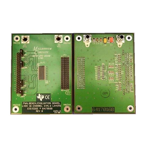
Page 9: Sn65Lvds387Evm
SN65LVDS387 16-Channel LVDS Line Driver Figure 2–2. SN65LVDS387EVM LVTTL Input Pins Enable/Disable LVDS Jumpers Output Pins Connector (Top) Side Component (Bottom) Side... -
Page 10: Sn65Lvds386 16-Channel Lvds Line Receiver
SN65LVDS386 16-Channel LVDS Line Receiver 2.2 SN65LVDS386 16-Channel LVDS Line Receiver The SN65LVDS386EVM accepts 16 LVDS inputs and generates 16 LVTTL outputs (refer to the schematic in Appendix I). Connectors P3 through P7 (right-side edge) accept the differential LVDS inputs and connector P1/P2 pro- vides the LVTTL output signals. - Page 11 SN65LVDS386 16-Channel LVDS Line Receiver Figure 2–3. SN65LVDS386EVM LVTTL Output Pins Enable/Disable LVDS Jumpers Input Pins Connector (Top) Side Component (Bottom) Side...
-
Page 12: Equipment Required
Chapter 3 Equipment Required This chapter provides guidance for selecting the test equipment required to use the EVM. Topic Page Pattern Generator ..........Oscilloscope and Scope Probes . -
Page 13: Pattern Generator
Vcc levels on each EVM may be evaluated. 3.4 Cables There are no cables provided with either the SN65LVDS387EVM or the SN65LVDS386EVM. When evaluating either the SN65LVDS387EVM or SN65LVDS386EVM separately, the only cables required are those connecting the input signal source to the input of the EVM. -
Page 14: Operation
......... . . System Evaluation Using Both the SN65LVDS387EVM and SN65LVDS386EVM . - Page 15 SN65LVDS387EVM Operation 4.1 SN65LVDS387EVM Operation The SN65LVDS387EVM is ready to be used as shipped. When connected to the test instrumentation and 3.3-Vdc power (as described in section 3), performance can be tested and observed. All I/O connections are made using standard BergSticks that allow fast and easy connections.
-
Page 16: Point-To-Point Configuration
These EVMs has been designed to allow performance evaluation of both de- vices when connected together. This allows users to perform tests using the specific type and length of cable between the SN65LVDS387EVM and the SN65LVDS386EVM. Users also has the option to install any specific connec- tors and to use jumper wires to the BergStick connectors. -
Page 17: Examples Of Multidrop Interconnections
System Evaluation Using Both the SN65LVDS387EVM and Figure 4–1. Examples of Multidrop Interconnections LVDS387 LVDS386 LVDS387 LVDS386 Termination Termination Termination Termination Termination Termination Four 1:4 Multidrops Single 1:16 Multidrop... -
Page 18: References
Note: When testing an SN65LVDS387EVM and SN65LVDS386EVM together, make sure R1 through R16 (100 Ω) are not installed on the SN65LVDS387EVM. Termination of the LVDS signal lines needs to be done on the SN65LVDS386EVM. 4.4 References There is a wide selection of LVDS devices and related applications materials available to assist in the design and development of LVDS interfaces. -
Page 19: A Parts List And Schematics
Appendix A Parts List and Schematics This appendix presents the parts list and schematics for as-shipped configura- tions of LVDS387 and LVDS386 EVMs. Note that equivalent parts may be used. Topic Page Parts List for EVMs ..........Schematics . -
Page 20: A.1 Parts List For Evms
Connector, header, 1 X 16P Header, 1 x 16, 0.1 ctrs 90F4440 P1, P2 Connector, header, 2 X 20P Header, male, 2 x 20, 0.1 ctrs Texas Instruments SN65LVDS387 Integrated circuit, SMT 16-Channel LVDS driver Texas Instruments SN65LVDS386 Integrated circuit, SMT 16-Channel LVDS receiver 4–103239–0X3... - Page 21 Schematic Diagrams 620201 and 6420202 A.2 Schematic Diagrams 620201 and 6420202 This section contains the following evaluation board schematic diagrams: 6420201, Schematic, Bench, Evaluation Board, SN65LVDS387DGG, 6420202, Schematic, Bench, Evaluation Board, SN65LVDS386DGG, Parts List and Schematics...
- Page 24 TI products. TI’s provision of these resources does not expand or otherwise alter TI’s applicable warranties or warranty disclaimers for TI products. Mailing Address: Texas Instruments, Post Office Box 655303, Dallas, Texas 75265 Copyright © 2019, Texas Instruments Incorporated...
Need help?
Do you have a question about the SN65LVDS387EVM and is the answer not in the manual?
Questions and answers