Table of Contents
Advertisement
Quick Links
Functional Safety and Redundant CAN Network
This User Guide details the SN65HVD257 CAN EVM (Controller Area Network Evaluation Module)
transceiver operation. It comes with two SN65HVD257 CAN transceivers factory installed, set up in a
redundant (parallel) CAN bus configuration. The EVM may be reconfigured by a user for other CAN
topologies. This User's Guide explains the EVM configurations for basic redundant CAN evaluation, and
includes various load and termination settings.
1
1.1
1.2
2
3
3.1
3.2
3.3
3.4
3.5
4
4.1
4.2
5
1
2
3
4
5
6
7
1
2
3
4
5
6
EVM Digital IO Configuration
SLLU172 - August 2012
Submit Documentation Feedback
..................................................................................................................
............................................................................................................
..................................................................................................
..................................................................................
..................................................................................
.....................................................................................................
.............................................................................................
.......................................................................................................
....................................................................................
..................................................................................
..................................................................................
.....................................................................................
............................................................................................
............................................................................................
SN65HVD257 CAN EVM: Functional Safety and Redundant CAN Network
Copyright © 2012, Texas Instruments Incorporated
SN65HVD257 CAN EVM:
Contents
........................................................................
.........................................................
......................................................
...........................................................
.................................................
List of Figures
.......................................................................
..................................................
List of Tables
.....................................................................
......................................................................
User's Guide
SLLU172 - August 2012
............
.....................................
.........
.....................................
2
2
2
4
7
7
9
10
11
11
12
12
12
14
2
3
3
4
5
13
13
6
7
9
10
11
11
1
Advertisement
Table of Contents

Subscribe to Our Youtube Channel
Related Manuals for Texas Instruments SN65HVD257


Summary of Contents for Texas Instruments SN65HVD257
-
Page 1: Table Of Contents
This User Guide details the SN65HVD257 CAN EVM (Controller Area Network Evaluation Module) transceiver operation. It comes with two SN65HVD257 CAN transceivers factory installed, set up in a redundant (parallel) CAN bus configuration. The EVM may be reconfigured by a user for other CAN topologies. -
Page 2: Introduction
RXD dominant time out and the FAULT output provides great flexibility, control and monitoring of these applications. A simple example of this flexibility is to use two SN65HVD257 devices combined logically in parallel via an AND gate to build a redundant (parallel) physical layer (cabling and transceivers) CAN network. Adding a logic XOR with a filter adds automatic detection for a fault where one of the 2 networks goes open (recessive) in addition to the faults detected by the SN65HVD257. -
Page 3: Typical Sn65Hvd257 Node To Build A Redundant Physical Layer Topology
These concepts can be expanded into other more complicated and flexible CAN network topologies to solve various other system-level challenges with a networked infrastructure. µP SN65HVD257 SN65HVD257 Bus 1 Bus 2 Figure 2. Typical SN65HVD257 Node To Build A Redundant Physical Layer Topology µP µP µP µP SN65HVD257 SN65HVD257... -
Page 4: Sn65Hvd257 Can Evm
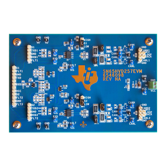
Common Mode (CM) Choke the EVM has footprints available for these components via customer installation of the desired component(s). Figure 4. SN65HVD257 CAN EVM Top SN65HVD257 CAN EVM: Functional Safety and Redundant CAN Network SLLU172 – August 2012 Submit Documentation Feedback... -
Page 5: Can Evm Schematic
SN65HVD257 CAN EVM www.ti.com Figure 5. CAN EVM Schematic SLLU172 – August 2012 SN65HVD257 CAN EVM: Functional Safety and Redundant CAN Network Submit Documentation Feedback Copyright © 2012, Texas Instruments Incorporated... -
Page 6: Sn65Hvd257 Can Evm Connections
Test Point FAULT (transceiver 2) test point TP24 Test Point CANL (bus 2) via 330Ω serial resistor test point SN65HVD257 CAN EVM: Functional Safety and Redundant CAN Network SLLU172 – August 2012 Submit Documentation Feedback Copyright © 2012, Texas Instruments Incorporated... -
Page 7: Sn65Hvd257 Evm Setup And Operation For Redundant (Parallel Networks)
SN65HVD257 EVM Setup and Operation for Redundant (Parallel Networks) www.ti.com SN65HVD257 EVM Setup and Operation for Redundant (Parallel Networks) This section describes the setup and operation of the EVM for parameter performance evaluation. Overview and Basic Operation Settings 3.1.1 Power Supply (TB1 or TP12 or JMP1) The basic setup of the EVM requires a single power supply to evaluate transceiver and network design performance. - Page 8 SN65HVD257 EVM Setup and Operation for Redundant (Parallel Networks) www.ti.com MODE SELECTION OPTIONS JMP1 configuration: Using header JMP1 (which assumes all the digital IO signals), V , GND are routed to an external system. Ensure that the MODE (JMP2 and JMP8) jumper settings are not conflicting with signals to JMP1.
-
Page 9: Using Can Bus Load And Termination Configuration
SN65HVD257 EVM Setup and Operation for Redundant (Parallel Networks) www.ti.com Using CAN Bus Load and Termination Configuration Each bus of the EVM is populated with two 120Ω power resistors selectable via jumpers between CANH and CANL. By using one of the resistors, the EVM may be used as a terminated end of a bus. For electrical measurements to represent the total loading of the bus, use both 120Ω... -
Page 10: Using Can Bus Protection And Filtering Configuration
SN65HVD257 EVM Setup and Operation for Redundant (Parallel Networks) www.ti.com Using CAN Bus Protection and Filtering Configuration The EVM also has component footprints for various protection schemes to enhance robustness for extreme system-level EMC requirements. Table 4 summarizes these options. Typical examples of for these components are: CM choke (TDK ACT45B series and EPCOS B82789 series from 11µH to 100µH),... -
Page 11: Using Customer Installable Io Options For Current Limiting, Pull Up Or Down, Noise Filtering
EVM. Replace or populate the RC components as necessary for the application. The RC output filter pads for may be reused as a resistor divider network to level shift the outputs down to 3.3V levels. The SN65HVD257 already has 3.3V compatible inputs on TXD and S pins. -
Page 12: Sn65Hvd257 Evm Configuration For Two Independent Networks
The RXD2 output of transceiver 2 (U5) is routed to JMP7 and TP21. If no parasitic loading to the combining AND gate U2 is desired, then R21 may be removed. SN65HVD257 CAN EVM: Functional Safety and Redundant CAN Network SLLU172 – August 2012 Submit Documentation Feedback Copyright ©... -
Page 13: Loopback Node 1 (Jmp5 To Jmp12)
CAN network. Figure 6. Loopback Node 1 (JMP5 to JMP12) Figure 7. Loopback Node 2 (JMP10 to JMP13) SLLU172 – August 2012 SN65HVD257 CAN EVM: Functional Safety and Redundant CAN Network Submit Documentation Feedback Copyright © 2012, Texas Instruments Incorporated... -
Page 14: Bill Of Material (Bom)
TP1, TP2, TP3, TP14, TP15, TP16 Test Point HDR_THVT_1x1_100 U1, U5 SN65HVD256D SOIC_8D U2, U3, U4 SN74AHC1G86DBV SOT_5DBV SOT_5DBV SN65HVD257 CAN EVM: Functional Safety and Redundant CAN Network SLLU172 – August 2012 Submit Documentation Feedback Copyright © 2012, Texas Instruments Incorporated... - Page 15 Evaluation Board/Kit Important Notice Texas Instruments (TI) provides the enclosed product(s) under the following conditions: This evaluation board/kit is intended for use for ENGINEERING DEVELOPMENT, DEMONSTRATION, OR EVALUATION PURPOSES ONLY and is not considered by TI to be a finished end-product fit for general consumer use. Persons handling the product(s) must have electronics training and observe good engineering practice standards.
- Page 16 IMPORTANT NOTICE Texas Instruments Incorporated and its subsidiaries (TI) reserve the right to make corrections, enhancements, improvements and other changes to its semiconductor products and services per JESD46, latest issue, and to discontinue any product or service per JESD48, latest issue.
- Page 17 Mouser Electronics Authorized Distributor Click to View Pricing, Inventory, Delivery & Lifecycle Information: Texas Instruments SN65HVD257EVM...
Need help?
Do you have a question about the SN65HVD257 and is the answer not in the manual?
Questions and answers