Advertisement
www.ti.com
EVM User's Guide: TPLD1201
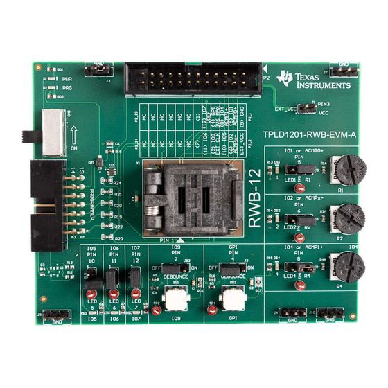
TPLD1201-RWB-EVM Evaluation Module
Description
The TPLD1201RWB evaluation module (EVM) is part
of the TI Programmable Logic Device (TPLD) family of
devices that feature versatile programmable logic ICs
with combinational logic, sequential logic and mixed-
signal functions to provide an integrated, compact,
low power design to implement common system
functions, such as timing delays, voltage monitors,
system resets, power sequencers, and I/O expanders.
The TPLD1201 helps users to configure
TPLD1201RWB devices without requiring the
soldering of the devices to the board. Users can
utilize InterConnect Studio (ICS) for fast evaluation,
development, simulation, and programming. Once
programmed, TPLD devices can be removed from the
socket and placed in a user's system.
Get Started
1. Order the TPLD1201-RWB-EVM and TPLD-
PROGRAM
2. Download the latest version of
Studio (ICS)
SCEU027B – NOVEMBER 2023 – REVISED OCTOBER 2024
Submit Document Feedback
3. Use the cables included the TPLD-PROGRAM kit
4. Place an unprogrammed TPLD1201RWB into the
Features
•
•
•
•
Applications
•
•
•
•
•
•
InterConnect
Copyright © 2024 Texas Instruments Incorporated
to connect the system
socket and configure using ICS
RWB socket for easy programming and evaluation
of TPLD1201RWB
Input buttons, potentiometers, and output LEDs for
quick evaluation
Header pins and test points for interfacing with
custom systems
Interfaces with TPLD-PROGRAM using a standard
keyed 14-pin cable
Factory automation and control
Communications equipment
Retail automation and payment
Test and measurement
Pro audio, video and signage
Personal electronics
TPLD1201-RWB-EVM Evaluation Module
Description
1
Advertisement
Table of Contents

Subscribe to Our Youtube Channel
Related Manuals for Texas Instruments TPLD1201


Summary of Contents for Texas Instruments TPLD1201
- Page 1 Input buttons, potentiometers, and output LEDs for system resets, power sequencers, and I/O expanders. quick evaluation • Header pins and test points for interfacing with The TPLD1201 helps users to configure custom systems TPLD1201RWB devices without requiring the • Interfaces with TPLD-PROGRAM using a standard soldering of the devices to the board.
-
Page 2: Kit Contents
Input 1.4 Device Information The TPLD1201 is part of the TI programmable logic device (TPLD) family of devices that features configurable I/O structures that extends compatibility within mixed-signal environments, reducing the number of discrete components required. System designers can create circuits and configure the macro-cells, I/O pins, and interconnections by temporarily emulating the non-volatile memory or by permanently programming the one-time programmable (OTP) through InterConnect Studio. - Page 3 2.1.3 External Connection Header Block The P2 header block is intended to be used to interface the TPLD1201-RWB-EVM with an external system. Using the guide printed on the EVM silkscreen, the TPLD pins can be interfaced with an external system to allow for prototyping and testing in customer systems.
- Page 4 Pin Number IO Name Testing Block Testing Block Name LED5 LED6 LED7 LED/POT LED4/R4 LED/POT LED2/R2 LED/POT LED1/R1 TPLD1201-RWB-EVM Evaluation Module SCEU027B – NOVEMBER 2023 – REVISED OCTOBER 2024 Submit Document Feedback Copyright © 2024 Texas Instruments Incorporated...
- Page 5 TPLD pin. Note The debounce circuit must not be connected on the GPI pin during programming. Figure 2-4. Switch Blocks SCEU027B – NOVEMBER 2023 – REVISED OCTOBER 2024 TPLD1201-RWB-EVM Evaluation Module Submit Document Feedback Copyright © 2024 Texas Instruments Incorporated...
- Page 6 0.2 V. When the POT is turned fully counterclockwise, the analog voltage source outputs at least VCC - 0.2 V. Figure 2-5. LED/POT Blocks TPLD1201-RWB-EVM Evaluation Module SCEU027B – NOVEMBER 2023 – REVISED OCTOBER 2024 Submit Document Feedback Copyright © 2024 Texas Instruments Incorporated...
-
Page 7: Installing Software
For more information on using InterConnect Studio (ICS), reference the InterConnect Studio User's Guide. 3.2 Configuring a TPLD Device This section covers the steps to use the TPLD1201-RWB-EVM and a TPLD-PROGRAM kit to program a TPLD1201RWB. SCEU027B – NOVEMBER 2023 – REVISED OCTOBER 2024... - Page 8 Software www.ti.com 3.2.1 TPLD1201-RWB-EVM Setup for Programming Make sure that the following conditions are met: 1. Set SW3 to the ON position. 2. Set the GPI Pin 4 jumper (J2) to the OFF position or remove the jumper 3. Remove the EXT_VCC (J1) jumper 4.
- Page 9 2. Connect the TPLD-PROGRAM to the TPLD1201-RWB-EVM using the provided 14-position ribbon cable. Make sure that a good connection is made between the TPLD1201-RWB-EVM and the TPLD-PROGRAM, indicated by the 3V3 LED in the top left of the EVM being on.
- Page 10 1. Open InterConnect Studio on the computer to which the TPLD-PROGRAM is connected. Under Design, select TPLD1201. Under Part:, select Default. Under Package:, select RWB (X2QFN, 12). 2. Search for TPLD1201 EVM Demo and select the demo from the list of pre-designed circuits, or select Empty Design to build a custom circuit.
- Page 11 3.3 Testing with the TPLD1201-RWB-EVM Demo This section is intended to be an example on how to use the TPLD1201-RWB-EVM to test a temporarily configured circuit. The TPLD1201 demo is designed to show the key functions of the TPLD1201, such as the internal oscillators, flip-flops, counters, gates, and analog comparators.
- Page 12 Software www.ti.com Figure 3-8. TPLD1201 EVM Demo TPLD1201-RWB-EVM Evaluation Module SCEU027B – NOVEMBER 2023 – REVISED OCTOBER 2024 Submit Document Feedback Copyright © 2024 Texas Instruments Incorporated...
- Page 13 ACMP0, output to LED6. Similarly, R4 can be turned to see the trigger of the analog comparator ACMP1 on LED7. SCEU027B – NOVEMBER 2023 – REVISED OCTOBER 2024 TPLD1201-RWB-EVM Evaluation Module Submit Document Feedback Copyright © 2024 Texas Instruments Incorporated...
- Page 14 Hardware Design Files www.ti.com 4 Hardware Design Files 4.1 Schematics Figure 4-1. TPLD1201-RWB-EVM Schematic TPLD1201-RWB-EVM Evaluation Module SCEU027B – NOVEMBER 2023 – REVISED OCTOBER 2024 Submit Document Feedback Copyright © 2024 Texas Instruments Incorporated...
-
Page 15: Pcb Layout
Hardware Design Files 4.2 PCB Layout Figure 4-2. TPLD1201-RWB-EVM Layout 4.2.1 PCB Overview Figure 4-3. TPLD1201-RWB-EVM Board Front SCEU027B – NOVEMBER 2023 – REVISED OCTOBER 2024 TPLD1201-RWB-EVM Evaluation Module Submit Document Feedback Copyright © 2024 Texas Instruments Incorporated... - Page 16 Hardware Design Files www.ti.com Figure 4-4. TPLD1201-RWB-EVM Board Bottom TPLD1201-RWB-EVM Evaluation Module SCEU027B – NOVEMBER 2023 – REVISED OCTOBER 2024 Submit Document Feedback Copyright © 2024 Texas Instruments Incorporated...
- Page 17 Hardware Design Files 4.3 Bill of Materials This section provides information on the components that can be used with the TPLD1201-RWB-EVM. Other components can be used as long as the components are able to fit the provided plated holes and pads.
-
Page 18: Revision History
Changes from Revision * (November 2023) to Revision A (November 2023) Page • Updated hardware image........................... • Updated Device Information section........................2 TPLD1201-RWB-EVM Evaluation Module SCEU027B – NOVEMBER 2023 – REVISED OCTOBER 2024 Submit Document Feedback Copyright © 2024 Texas Instruments Incorporated... - Page 19 TI products. TI’s provision of these resources does not expand or otherwise alter TI’s applicable warranties or warranty disclaimers for TI products. TI objects to and rejects any additional or different terms you may have proposed. IMPORTANT NOTICE Mailing Address: Texas Instruments, Post Office Box 655303, Dallas, Texas 75265 Copyright © 2024, Texas Instruments Incorporated...
Need help?
Do you have a question about the TPLD1201 and is the answer not in the manual?
Questions and answers