
Related Manuals for Airwell AW-XDO009-H11


Summary of Contents for Airwell AW-XDO009-H11
- Page 1 Installation manual Direct expansion console water source DC Inverter technology Silent heat pump...
- Page 2 By following the suggestions contained in this manual, the product you have purchased will operate without problems, giving you optimum room temperatures with minimum energy costs. Airwell. Compliance This unit complies with the following European Directives: •...
-
Page 3: Table Of Contents
General General warnings Fundamental safety rules Description Storage Handling Shipping dimensions and weight Supplied components Unit parts Installation Installation method Choosing the position of the unit Assembling the unit Condensation drain preparation Mounting the appliance on the bracket Hydraulic connection Electrical connection High/low installation configuration Setting cool only or heat only modes... -
Page 4: General
GENERAL General warnings After unpacking, check that the contents are intact and that Do not leave the room closed for long. Periodically open the all parts are included. If not, contact the agent who sold the windows to ensure proper ventilation. appliance to you. -
Page 5: Description
GENERAL Description The air conditioning unit XDO is the new solution that represents EER more off 4.5, this is the cutting edge in the sector of monobloc a significant step towards reducing the aesthetic impact of air climate control systems with fixed installation. conditioners. -
Page 6: Handling
GENERAL Handling The unit is packed singularly in a cardboard box. The appliance is unbalanced on the right Boxes can either be carried singularly by hand by two (compressor side). operators or loaded on a forklift truck, for a maximum of three units. -
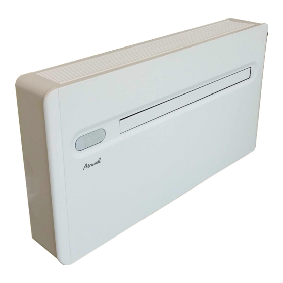
Page 7: Unit Parts
GENERAL Unit parts Air outlet flaps Air Filter Touch screen display Anti-lifting bracket Front panel Room air probe Water input (Eurokonus M 3/4") Power supply terminal block Water output (Eurokonus M 3/4") Decorative side panel Internal air intake grille Modulating Valve Kit... -
Page 8: Installation
INSTALLATION INSTALLATION Installation method Before installing the conditioner, it is essential to calculate Therefore, try to reduce higher heat loads by following the summer thermal loads (and winter ones for the models instructions below: with a heat pump) of the room. The more exact the - Cover large windows exposed to sunlight with curtains calculation, the better the product will work. -
Page 9: Assembling The Unit
INSTALLATION Assembling the unit 1.11 To install the unit on a wall, drill 6 holes to attach the fixing The manufacturer cannot be held responsible for plate to the wall as indicated on the drilling template. The any underestimation of the structural consistency of the appliance weighs more on the right, so make sure to secure anchoring carried out by the installer. -
Page 10: Condensation Drain Preparation
INSTALLATION 1.12 Condensation drain preparation For machines that also operating in cooling mode, the close the container hermetically and avoid immersing the condensate drain pipe (16mm internal diameter, not draining pipe into the water. supplied) must be connected to the unit to the pipe in the hydraulic connection compartment. -
Page 11: Mounting The Appliance On The Bracket
INSTALLATION 1.13 Mounting the appliance on the bracketMounting the appliance on the bracket After checking that the bracket is anchored to the wall and After performing the operations, make sure that there are no that all necessary electrical connections and condensation gaps behind the appliance. - Page 12 INSTALLATION Hydraulic connections IMPORTANT The inversion of the inlet/outlet connections can cau- se malfunctions and may damage the appliance Hydraulic devices to be integrated for safety As mentioned previously, the installer must provide some In particular, the devices indicated in the figure below must devices for the safety and proper maintenance of the be installed.
- Page 13 INSTALLATION 1.15 Hydraulic and chemical characteristics of water The internal water supply circuit has a two-way modulating The KVS of the valve used is: valve, driven directly from the interface by the machine Kv (m³/h with ∆p = 100kPa = 1bar) = 1.2 controller, which monitors the temperature of the water leaving the exchanger adjusting the flow to the exchanger The general expression (valid for water or technically similar...
-
Page 14: Electrical Connection
INSTALLATION 1.16 Electrical connection The appliance comes with a power cable with a F+E type It is possible to carry out the electrical connection using plug (CEE 7/7 schuko plug). a cable inside of the wall as indicated in the installation The cable can only be replaced by the manufacturer, by the template (recommended for installations in the upper part service centre or by a qualified installer. - Page 15 INSTALLATION CP occupancy contact input connection Near the main terminal board there is another terminal device that inhibits the functioning of the appliance such board with 2 terminals featuring the CP label. as: open window contact, on/off remote, infrared presence When the CP contact opens (very low voltage, connected to sensors, enabling badge, etc.
-
Page 16: High/Low Installation Configuration
INSTALLATION 1.17 High/low installation configuration The unit can be installed either in the lower part (near the (coanda effect). floor) or in the upper part (near the ceiling) of the wall. In this case, purchase the lower cover decorative kit code In order to optimise air distribution and comfort, the GB0737. -
Page 17: Setting Cool Only Or Heat Only Modes
INSTALLATION 1.18 Setting cool only or heat only modes It is possible to deactivate the heating or the cooling modes only) mode. following a simple procedure. Press the A key again to switch back to HO (heating only) Keep the A key on the touch-screen display pressed for 5 mode. - Page 18 INSTALLATION Use of the appliance Objects or structural obstacles (furniture, curtains, plants, The appliance must not be installed in rooms where leaves, blinds, etc.) must not obstruct the normal air flow explosive gases develop or where there are humidity and both from the internal and from the external grids.
-
Page 19: Periodic Maintenance
MAINTENANCE MAINTENANCE Periodic Maintenance The air conditioner you have bought has been designed to only include the following cleaning operations: keep maintenance operations to a minimum, in fact, they External cleaning Disconnect the unit from the power supply before each Pay attention to the sharp edges. -
Page 20: Troubleshooting
MAINTENANCE Troubleshooting In the even of a malfunction, please refer to the following table. please contact the authorised technical assistance. If, after performing the suggested checks, the problem is not solved, Fault Possible causes Solution Check there is power supply (by turning a light on, for example). Check that the thermal-magnetic circuit breaker used exclusively to protect The appliance No power supply... -
Page 21: Technical Specifications
MAINTENANCE Technical specifications Please read data plate to obtain the technical data listed below. Power supply voltage Maximum absorbed power Maximum absorbed current Amount of refrigerant gas Casing protection rating Technical specifications Size XDO 09 XDO 012 Cooling Cooling capacity 2.53 3.56 Total power input... - Page 23 D. Lgs. no. 15 of 16/02/2011 -Responsible to constitute the technical file is the company Airwell Residential SAS - 3, Avenue du Centre, Les Quadrants BAT. A - 78280 Guyancourt- FR -Responsable pour compiler le dossier technique est la société Airwell Residential SAS - 3, Avenue du Centre, Les Quadrants BAT. A - 78280 Guyancourt- FR -Responsabile a costituire il fascicolo tecnico è...
- Page 24 AIRWELL RESIDENTIAL 3 Avenue du Centre - Les Quadrants - Bâtiment A - 78280 - GUYANCOURT– France Tel. +33 (0)1 76 21 82 00 - www.airwell-pro.fr - contact@airwell-res.com...
Need help?
Do you have a question about the AW-XDO009-H11 and is the answer not in the manual?
Questions and answers