Advertisement
Introduction
Description
© 2002Johnson Controls, Inc.
Part No. 24-8980-2, Rev. A
Code No. LIT-6363155
T
ECHNICAL
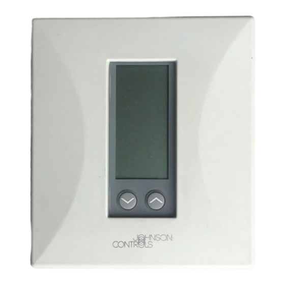
TEC1100 Series Thermostat
In this document, Building Automation System (BAS) is a generic term
that refers to the Metasys® Network (Network Control Module [NCM] or
N30 series), Companion, and Facilitator® supervisory systems. When you
refer to system specific applications, use the specific system names.
The TEC1100 Series includes three nonprogrammable models:
single-stage (TEC1101), heat pump (TEC1102), and multistage
(TEC1103). The applications include furnace, air conditioner, heat pump,
and rooftop units. The TEC1100 incorporates fuzzy logic for precise
control in a thermostat type package.
All TEC1100s have Metasys N2 communication capability. This
communication allows the user to view and adjust parameters from a
remote workstation. It also provides information, such as outdoor air
temperature, to the TEC1100 units on the bus. The thermostat is easy to
operate and normally displays room temperature and mode of operation
using Cooling ( ) or Heating ( ) icons. When there is a call for cooling,
the Snowflake icon ( ) blinks. Likewise, during a call for heating, the
Flame icon ( ) blinks. When the temperature is satisfied, neither icon
blinks. In the Auto mode, both icons (
satisfied. Light-Emitting Diodes (LEDs) on the top of TEC1102/1103
models use Binary Inputs (BIs) to indicate a clogged filter and external
service. A unique temperature alarm (BI 2) indicates that the zone
temperature has not been satisfied in 45 minutes.
B
ULLETIN
) appear continuously when
Issue Date
August 8, 2002
www.johnsoncontrols.com
1
Advertisement
Table of Contents

Related Manuals for Johnson Controls METASYS TEC1100 Series


Summary of Contents for Johnson Controls METASYS TEC1100 Series
- Page 1 Issue Date August 8, 2002 ECHNICAL ULLETIN TEC1100 Series Thermostat In this document, Building Automation System (BAS) is a generic term Introduction that refers to the Metasys® Network (Network Control Module [NCM] or N30 series), Companion, and Facilitator® supervisory systems. When you refer to system specific applications, use the specific system names.
- Page 2 LEDs (TEC1102, TEC1103 only) indicate system activity or problems (see Table 3). Used to select Heating, Cooling, Auto, Off, or Emergency Heat Mode Outdoor (E ht; available on TEC1102 Used to display outside only) mode of operation. temperature (optional). Day/Night Used to alternate between Used to run fan day and night setpoints.
- Page 3 The performance specifications are nominal and conform to acceptable industry standards. For application at conditions beyond these specifications, consult the local Johnson Controls office. Johnson Controls, Inc. shall not be liable for damages resulting from misapplication or misuse of its products.
- Page 4 Table 2: TEC1100 Series Accessory Ordering Information Item Product Code Number Optional Accessories (includes mounting hardware) Replacement Door for nonprogrammable thermostat (10/box) TEC10DOOR-NONPROG Remote or Averaging Indoor Temperature Sensor SEN-500-1* Outdoor Air Sensor with Outdoor Air Temperature Communication Module SEN-500-2** Duct Mounted Outdoor Air Sensor with Outdoor Air Temperature SEN-500-3** Communication Module...
- Page 5 Table 4: Applications Application Recommended Model Fan Coil Unit TEC1101-1 Heat Pump TEC1102-1 Unit Heaters TEC1101-1 Packaged Rooftop TEC1103-1 and Separate Economizer Package (M130EAA-2 or equal in place of Stage 1). Refer to the AD-DME1702-1 Direct Mount Economizer Controller Technical Bulletin (LIT-6363020). Packaged Heating/Cooling TEC1101-1 or TEC1103-1 Installation...
- Page 6 Mount tec1100 Figure 2: Separating and Mounting the TEC1100 3. Grasp the base from the bottom two corners, and separate from the thermostat. 4. Swing the thermostat out from the bottom, and lift up and out from the base. Note: When replacing an existing thermostat, use wire tags to identify terminal designations.
-
Page 7: Setting The Dip Switches
Setting the DIP Select Dual Inline Package (DIP) switches to perform a variety of Switches different functions: fan runtime delay, keyboard disable, and multistage heating or cooling. Note: Before selecting a minimum On/Off time for the TEC1100 Series, verify the equipment can tolerate the following hourly maximum cycle rates: 7.5 cycles per hour when using 4-minute On/Off (preferred for energy savings) or 15 cycles per hour when using 2-minute On/Off. - Page 8 Table 6: TEC1101 Single-Stage Output Terminal Designations Terminal Function Energizes on call for heating. Energizes on call for cooling. Energizes fan on call for heating or cooling or by pressing the Fan button. Provides independent switching voltage. Provides 24 VAC from equipment transformer. 24V(c) Provides 24 VAC (common) from equipment transformer.
- Page 9 TEC1102 Heat Pump Wiring Configuration and DIP Switch Settings Table 7: TEC1102 Heat Pump DIP Switch Selections DIP Switch Selection Description Compressor/Auxiliary Interlocked: turns off the compressor when the auxiliary heat (E ht) is on. The compressor remains off for 2 minutes after the auxiliary heat is turned off to ensure that the heat pump coil has cooled.
- Page 10 Compressor/Auxiliary Compressor/Auxiliary Normal Interlocked Not Used Not Used Heat/Cool: 4 Minute Heat/Cool: 2 Minute (Minimum On/Off) (Minimum On/Off) Keyboard Unlocked Keyboard Locked Economy Comfort Single-Stage Multistage TEC1102 LED 1 Icon Off LED1 2nd Stage Compressor LED 1 Icon (Filter) Auxiliary Heating LED2 LED 2 Icon Off LED 2 Icon...
- Page 11 Metasys If the transformer (T2) is to power all of the loads, the CPN, FAC, yellow pin jumper must be inserted connecting R to 24 V. The jumper is located on the electronics board above the relays. If a separate 24 V transformer (T1) is to be used, it must be connected between R and 24 V(c), and the jumper should be removed between R and 24 V.
- Page 12 TEC1103 Multistage Wiring Configuration and DIP Switch Settings Table 9: TEC1103 Multistage DIP Switch Selections DIP Switch Selection Description Allows 2-minute minimum On/Off time for heating or cooling equipment. Allows 4-minute minimum On/Off time for heating or cooling equipment (preferred). Locks the keyboard, disabling buttons to prevent tampering.
-
Page 13: Connecting The N2 Bus
Table 10: TEC1103 Multistage Output Terminal Designations Terminal Function Energizes on call for second stage heat. Energizes on call for second stage cooling. Energizes on call for first stage heat. Energizes on call for first stage cooling. Energizes fan on call for heating or cooling or by pressing the Fan button. Independent switching voltage 24 VAC from equipment transformer 24V(c) - Page 14 NCM300 Series NCM200 Series Port 1 - N2 Bus (TB1 or Communicator Terminal Board) TEC1100 Next Tec 1100 ncm Device Figure 9: Connecting the TEC1100 to an NCM Connecting to N30 Series 24 VAC TEC1100 Next Tec 1100n30 N2 REF Device Figure 10: Connecting the TEC1100 to the N30 Series Connecting to...
-
Page 15: N2 Device Mapping
Connecting to Network Display N2 ADDRESS Module (NDM) NU-NDM101-0 TEC1100 REV - M9426 N2 TRANSMIT N2 RECEIVE POWER 9-12 VAC/DC N2 END 0.5A OF LINE OUT IN © 1995 4100/D01/03 tec1100ndm Figure 12: Connecting the TEC1100 to the NDM Setting the N2 To set the N2 Address: Address 1. - Page 16 Table 11: N2 Bus Objects Point Name Override Range Point (CPN/ Model 1101 1102 1103 Type/ FAC) Point Addr. Object Type Type Room Temp ADI-1 N2 AI CSAD ADI1 0 to 48°C ♦ ♦ ♦ (AI) (28 to 124°F) Outdoor Temp ADI-2 N2 AI CSAD ADI2...
-
Page 17: Installing The Thermostat Cover Lock
Point Name Override Range (Cont.) Point (CPN/ Model 1101 1102 1103 Type/ FAC) Point Addr. Object Type Type Y1 State BD-6 N2 BI CSBD BD6 0 = Off, 1 = On Cool 1 Comp 1 Cool 1 (BI) Y2 State BD-7 N2 BI CSBD BD7... - Page 18 Plastic Hinged Lock Pins Tabs Thermostat Base Snap plastic lock Insloc piece into place. Figure 13: Installing the Thermostat Cover Lock Reattaching the To reattach the thermostat: Thermostat 1. Position the thermostat inside the cover, and attach on the hinged tabs located at the top of the base.
- Page 19 TEC1100 Features Table 12: TEC1100 Features Feature Description Control Over time, the TEC1100 learns how long it takes the system to meet the load. If the system Algorithm can change the room temperature quickly, the TEC1100 allows the thermostat to drift further from setpoint before starting the equipment.
- Page 20 Commissioning Verifying Proper To verify proper thermostat operation: Thermostat Press the Mode button to select the Heating or Cooling mode. Operation Press the ∨ or ∧ buttons to raise the setpoint above or below the current ambient temperature. The thermostat calls for either heating or cooling.
- Page 21 Selecting a Press the ∨ and ∧ buttons simultaneously to alternate between Celsius and Temperature Fahrenheit display. This does not affect the BAS display. For example, Scale hotel room temperature can be displayed in °F on the Companion system, but a hotel guest can switch the local display to °C. If power loss occurs, the TEC reverts to the last network command (in this example, °F).
-
Page 22: Sensor Calibration
Selecting Day or When the TEC1100 Series thermostat is first installed, or after a power Night Mode ( loss, the display shows the Day icon ( ) and the temperature. Once the BAS overrides the Day/Night mode, the corresponding symbol appears. To select Day or Night mode: •... -
Page 23: Troubleshooting
Troubleshooting N2 Bus See Table 14 if the TEC1100 thermostat does not function properly during Configuration N2 Bus Configuration. Troubleshooting Table 14: N2 Bus Configuration Troubleshooting Error/Trouble Possible Causes Solution Condition TEC1100 cycles online Two or more controllers have the Change each duplicate address to a unique and offline. - Page 24 Occupant Zone temperature control problems, usually reported as occupant hot/cold Hot/Cold complaints, can have causes ranging from the building or mechanical Complaints system to the control components. Table 15 helps locate the cause of zone Troubleshooting temperature control problems with TEC1100 Series thermostats. Table 15: TEC1100 Series Thermostat Troubleshooting Symptom Possible Cause...
Need help?
Do you have a question about the METASYS TEC1100 Series and is the answer not in the manual?
Questions and answers