Table of Contents
Advertisement
TEC3000 Series Networked and Wireless Single- or
Two-stage Economizer Thermostat Controllers
Quick Start Guide
TEC3330-1x-xxx, TEC3331-1x-xxx, TEC3630-1x-xxx, TEC3631-1x-xxx,
TEC3030-1x-xxx, TEC3031-1x-xxx
North American emissions compliance
United States
This equipment has been tested and found to comply with the limits for a Class B digital device, pursuant to Part
15 of the FCC Rules. These limits are designed to provide reasonable protection against harmful interference in
a residential installation. This equipment generates, uses and can radiate radio frequency energy and, if not
installed and used in accordance with the instructions, may cause harmful interference to radio communications.
However, there is no guarantee that interference will not occur in a particular installation. If this equipment does
cause harmful interference to radio or television reception, which can be determined by turning the equipment off
and on, the user is encouraged to try to correct the interference by one or more of the following measures:
•
Reorient or relocate the receiving antenna.
•
Increase the separation between the equipment and receiver.
•
Connect the equipment into an outlet on a circuit different from that to which the receiver is connected.
•
Consult the dealer or an experienced radio/TV technician for help.
Canada
This Class (B) digital apparatus meets all the requirements of the Canadian Interference-Causing Equipment
Regulations.
Cet appareil numérique de la Classe (B) respecte toutes les exigences du Règlement sur le matériel brouilleur
du Canada.
Installation
Parts included
•
One TEC3000 Series Thermostat Controller with integral mounting base
•
One installation instructions sheet
Location considerations
For networked models, locate the TEC3000 Series Thermostat Controller:
•
On a partitioning wall, approximately 5 ft (1.5 m) above the floor in a location of average temperature, allowing
for vertical air circulation to the TEC
•
Away from direct sunlight, radiant heat, outside walls, outside doors, air discharge grills, stairwells, and from
behind doors
•
Away from steam or water pipes, warm air stacks, unconditioned areas (not heated or cooled), or sources of
electrical interference
•
In a clear path between the integrated passive infrared (PIR) occupancy sensor (if equipped) and the space
being monitored
Refer to the
TEC3000 Series Networked and Wireless Single- or Two-stage
Economizer Thermostat Controllers Quick Start Guide
*241135300036C*
24-11353-00036, Rev. C
(barcode for factory use only)
Part No. 24-11353-00036, Rev.
QuickLIT website
for the most up-to-date version of this document.
1
C
Issued May 2019
Advertisement
Table of Contents

Related Manuals for Johnson Controls TEC3330-1 Series


Summary of Contents for Johnson Controls TEC3330-1 Series
- Page 1 *241135300036C* 24-11353-00036, Rev. C (barcode for factory use only) TEC3000 Series Networked and Wireless Single- or Two-stage Economizer Thermostat Controllers Quick Start Guide Part No. 24-11353-00036, Rev. Issued May 2019 TEC3330-1x-xxx, TEC3331-1x-xxx, TEC3630-1x-xxx, TEC3631-1x-xxx, TEC3030-1x-xxx, TEC3031-1x-xxx Refer to the QuickLIT website for the most up-to-date version of this document.
- Page 2 For wireless models, also locate the thermostat controller: • Outside of a recessed area, metal enclosure, or shelving unit • On the same building level as the other wireless devices on the same personal area network (PAN) • At least 2 in. (51 mm) away from any metal obstruction •...
-
Page 3: Installing The Thermostat Controller
Installing the thermostat controller 1. Use a 1/16 in. (1.5 mm) Allen wrench or Johnson Controls® T-4000-119 Allen-Head Adjustment Tool (order separately) to remove the security screw if it is installed on the top of the thermostat controller cover as illustrated in Figure 2. - Page 4 Figure 2: Removing the security screw from the thermostat controller cover (shown without occupancy sensor) (left) and removing the thermostat controller cover (right) 3. Align the thermostat controller mounting base on the wall with the security screw on the top and use the base as a template to mark the two mounting hole locations.
- Page 5 Figure 3: Mounting hole locations, dimensions, in. (mm) (left) and securing the thermostat controller mounting base to the wall (right) Note: When the unit is mounted on the wall, you can hang the front cover on the end of the back cover as illustrated in Figure 4.
- Page 6 Wiring When an existing thermostat controller is replaced, remove and label the wires to identify the terminal functions. Risk of Electric Shock. Disconnect the power supply before making electrical connections to avoid electric shock. Risque de décharge électrique. Débrancher l'alimentation avant de réaliser tout raccordement électrique afin d'éviter tout risque de décharge électrique.
- Page 7 6. Use a 1/16 in. (1.5 mm) Allen wrench or Johnson Controls T-4000-119 Allen-Head Adjustment Tool (order separately) to reinstall the security screw on the top of the thermostat controller cover. See Figure 2 for security screw placement.
- Page 8 Table 2: Terminal identification (See Figure 5 and Figure 6 for wiring diagrams) Terminal label Function TEC3030, TEC3031 TEC3330, TEC3331 TEC3630, TEC3631 24 V 24 VAC hot from the sensor Cooling stage 1 Cooling stage 2 Auxiliary binary output Auxiliary power W1 OB Heating 1 (RTU mode)/Reversing valve (O/B) (Heat Pump mode) Power for W1 and W2...
- Page 9 Figure 5: Staged wiring diagram - rooftop unit (See Table 2 for terminal identification) TEC3000 Series Networked and Wireless Single- or Two-stage Economizer Thermostat Controllers Quick Start Guide...
- Page 10 Figure 6: Staged wiring digram - heat pump (See Table 2 for terminal identification) TEC3000 Series Networked and Wireless Single- or Two-stage Economizer Thermostat Controllers Quick Start Guide...
-
Page 11: Setup And Adjustments
Figure 7: AUX contact wiring 19 to 30 VAC AUX Contact Load Figure 8: Binary input wiring Dry Contact Dry Contact Setup and adjustments IMPORTANT: Table 6 provides a full list of TEC3000 menu settings. Refer to TEC3000 Series Networked and LIT-12013163 Wireless Single- or Two-Stage Economizer Thermostat Controllers Installation Instructions ( ) for... -
Page 12: Customizing The Home Screen
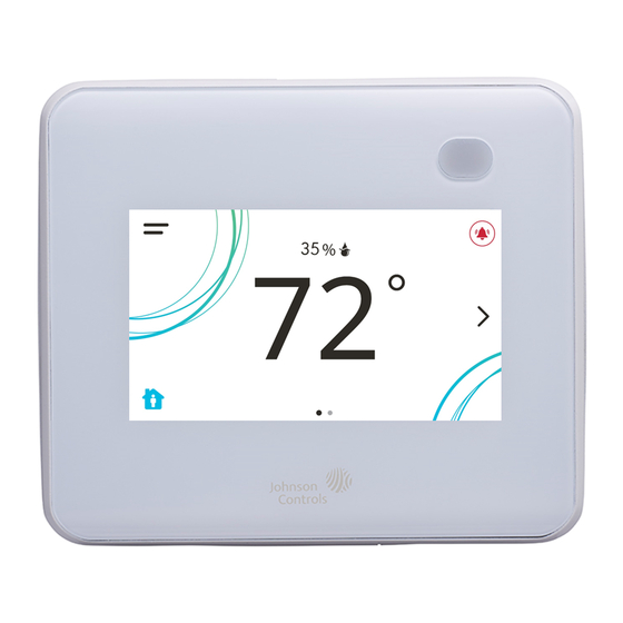
In the modern theme, the cooling, or blue, and heating, or orange, circles show whether the cooling or heating mode is active. Figure 10: Thermostat controller home screen in cooling mode (left) and heating mode (right) Customizing the home screen Customizing the Home screen settings include: •... - Page 13 Table 3: Touchscreen icons (Part 2 of 4) Icon and icon name Description Powers the thermostat controller on or off. Notes: • This icon disables all equipment control but does not physically power down the unit. • On the modern home screen, if the Unit Power icon is in standby mode, the Unit Power temperature and humidity are also...
- Page 14 Table 3: Touchscreen icons (Part 3 of 4) Icon and icon name Description Displays the current cooling setpoint. Indicates that Hold mode is disabled. To enable Hold mode, press the button. Cooling Setpoint Displays the current heating setpoint. Indicates that Hold mode is disabled. To enable Hold mode, press the button.
-
Page 15: User Lockout
Table 3: Touchscreen icons (Part 4 of 4) Icon and icon name Description Moves the display to the previous screen. Back Moves the display to the next screen. Forward Returns the display to the main home screen. Home Saves the current configuration and parameter settings. - Page 16 Configuring the thermostat controller Use the Menu icon on the home screen to access and change the basic operating parameters of the thermostat controller. During normal operation, press the Menu icon once to access the following parameters: • Fault Status •...
-
Page 17: Configuring The Zone Space Or Equipment Size
• On—Fan is continuously on • Auto—Fan cycles on demand with the controller entering cooling, heating, or dehumidification modes • Smart—Fan cycles on demand with the controller entering cooling or heating modes during unoccupied periods but is continuously running during occupied and standby periods The Fan Override icon on the home screen is dependent on the fan type. -
Page 18: Setting The Local Schedule
Scheduling (for all models) The occupancy schedule comes from either the weekly scheduler built into the TEC or as an input from the BAS. The Schedule Source must be selected to tell the controller where to read the occupancy source from. Setting the local schedule A weekly occupancy schedule with up to four occupancy events for each day can be set locally on the TEC and operate independently of a supervisor. -
Page 19: Menus And Submenus
Menus and submenus In the following table, the * indicates that the menus depend on your configuration. Table 6: Menus and submenus (Part 1 of 5) Level 1 Level 2 (LCD screen name) Setpoints Occupied Cooling Occupied Heating Unoccupied Cooling Unoccupied Heating Standby Cooling Standby Heating... - Page 20 Table 6: Menus and submenus (Part 2 of 5) Level 1 Level 2 (LCD screen name) Display Settings Units Time Time Zone Set Time Format Date Set Date Format Language Show Fan Button on Home Show Temp on Home Show Humidity on Home Show Off Button on Home Show Hold Button Show Setpoint on Home...
- Page 21 Table 6: Menus and submenus (Part 3 of 5) Level 1 Level 2 (LCD screen name) Setup (Cont) Zone Temp Offset Reset Sensors Zone Temp Alarm Enabled (for TEC networked models) Zone Temp Low Limit (for TEC networked models) Zone Temp High Limit (for TEC networked models) Tuning Temp Control Setup Reset PID Tuning...
- Page 22 Table 6: Menus and submenus (Part 4 of 5) Level 1 Level 2 (LCD screen name) Equipment Setup General Number of Compressors Lead/Lag Equalize Runtime Number of Heating Stages* Compressor Min On Time Compressor Min Off Time Heating Min On Time Heating Min Off Time Supp Min On Time Supp Min Off Time...
- Page 23 Table 6: Menus and submenus (Part 5 of 5) Level 1 Level 2 (LCD screen name) System Status Occupancy Source Unit Status Supply Air Temperature Cooling OAT Lockout Heating OAT Lockout Comp Low OAT Lockout Supp High Lockout Temp Zone Temp Source Control Status Cooling % Command Heating % Command...
-
Page 24: Troubleshooting
Internal Sensor Fail An internal sensor has failed on the Order replacement units and return the affected TEC. devices to Johnson Controls under the RMA program. OA Lockouts Disabled The Local Outdoor Air Temperature 1. If the source of outdoor air temperature was a... - Page 25 Controller Fault The controller has detected an internal Order replacement units and return the affected fault that it cannot recover. devices to Johnson Controls under the RMA program. An unknown error has prevented the Order replacement units and return the affected controller from turning on.
- Page 26 Table 7: Fault list (Part 3 of 3) Faults Probable causes Solutions Heating Ineffective The Supply Air Temperature has not Verify that the heating elements on the rooftop increased above the configured Supply are functioning properly. Air Temperature Alarm Offset while heating has been active for at least the Supply Air Temperature Alarm Delay.
- Page 27 Table 8: Troubleshooting details (Part 2 of 3) Symptom Probable causes Solutions The heat pump does not sequence The heat pump requires Consult the equipment documentation to verify properly. traditional wiring (Y1, Y2, W1, wiring configuration, then set Heat Pump W2, and G) and handles the Supported to No.
-
Page 28: Repair Information
Repair Information If the TEC3000 Series Thermostat Controller fails to operate within its specifications, replace the unit. For a replacement thermostat controller, contact the nearest Johnson Controls representative. TEC3000 Series Networked and Wireless Single- or Two-stage Economizer Thermostat Controllers Quick Start... -
Page 29: Technical Specifications
Technical specifications TEC3000 Series Networked and Wireless Single- or Two-Stage Economizer Thermostat Controllers (Part 1 of 2 ) Power requirements 19 to 30 VAC, 50/60 Hz, 4 VA at 24 VAC nominal, Class 2 or safety extra-low voltage (SELV) USB port power rating 120 to 250 mA current draw supported Relay contact rating 19 to 30 VAC, 1.0 A maximum, 15 mA minimum, 3.0 A in-rush, Class 2 or SELV... -
Page 30: Software Terms
The performance specifications are nominal and conform to acceptable industry standards. For application at conditions beyond these specifications, consult the local Johnson Controls office. Johnson Controls shall not be liable for damages resulting from misapplication or misuse of its products.
Need help?
Do you have a question about the TEC3330-1 Series and is the answer not in the manual?
Questions and answers