Table of Contents
Advertisement
Advertisement
Table of Contents

Related Manuals for STIEBEL ELTRON Stratos Brahma Series


Summary of Contents for STIEBEL ELTRON Stratos Brahma Series
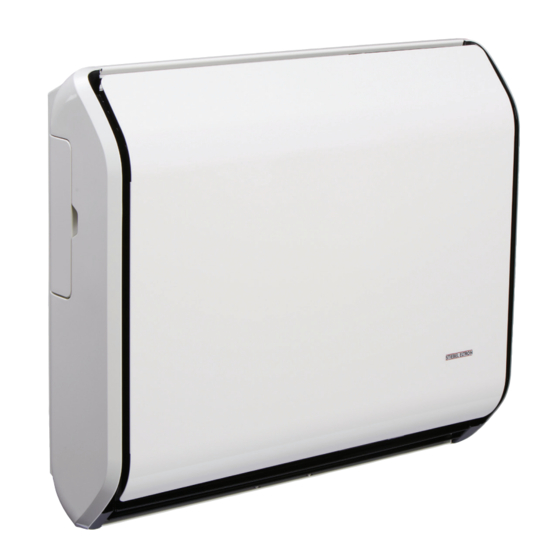
- Page 1 Gas Room Heater Stratos Brahma...
- Page 2 COMPLIANCE Our appliance shall be installed in accordance with AS/NZS 5601.1, and local authority requirements. This appliance must only be installed by an authorised person. RANGE MODEL CODE S t r a t o s 3 . 0 S R 3 0 M 0 M 0 3 0 0 S t r a t o s 5 .
-
Page 3: Warranty
Dear Customer We inform you that this unit has a warranty specification (see specifications in the text to follow). During the first switch on, there may be vapor emissions, or bothersome odors absolutely not dangerous. In these cases, you should operate the device at the maximum power for several hours, keeping the room well ventilated. - Page 4 INDEX GENERAL General informations pag.5 Safety rules pag.5 Appliance description pag.6 Identification pag.6 Structure pag.7 Technical data pag.8 Accessories pag.8 Electrical scheme pag.9 Control panel pag.10 INSTALLATION Receiving the product pag.11 Weight and dimension pag.12 Installation: WALL FITTING or FLOOR STANDING - Apparatus choice location pag.13 - Intake &...
-
Page 5: General Informations
GENERAL INFORMATIONS After removing the packaging, check the integrity of the This booklet is an integral part of the appliance and contents. In case of discrepancies, contact the Agency must therefore be carefully looked after and ALWAYS that sold the appliance. accompany the APPLIANCE, including when this is sold to another user or transferred to another system. -
Page 6: Appliance Description
APPLIANCE DESCRIPTION The appliance is a gas radiator that heats up the atmo- It also has an electrical device that allows you to do a sphere. series of things. It has an intake of air that goes into the combustion There also is a Processor Control Box (P.C.B assy) that chamber type C. - Page 7 STRUCTURE ...
-
Page 8: Technical Data
TECHNICAL DATA Gas consumption Minimum consumption Test point pressure Minimum test point pressure Injector size Electrical rating GENERAL... -
Page 9: Electrical Scheme
ELECTRICAL SCHEME GENERAL... -
Page 10: Control Panel
CONTROL PANEL - On/Off key and device RESET - Reduce temperature key (MIN 5°C) - Light display - Increase temperature key (MAX 35°C) - Enable/disable Wireless command key DESCRIPTION OF DISPLAY DESCRIPTION OF ICONS This type of screen simultaneously provides an 1 - operation at MAX power. -
Page 11: Receipt Of Product
RECEIPT OF PRODUCT The appliance is supplied in one cardboard package: Contents of appliance package: Appliance Manual control Metal template Pipe KIT: 1 Adapter union 1 Suction pipe (L = 500mm) (Ø 32mm Mod. 3.0 - 5.0) (Ø 54mm Mod. 7.0 - 9.0) 1 exhaust pipe (L = 500mm) (Ø... - Page 12 WEIGHT & DIMENSION Gas and electrical connection location measurements Gas connection Electrical connection INSTALLER...
- Page 13 INSTALLATION: WALL FITTING or FLOOR STANDING GENERAL INFORMATION -When the appliance is being installed do not use parts that are not from the manufacturer. -Don’t let the electrical cable touch heated parts, like the grill or the intake & exhaust tubes. -Don’t block with anything, the heaters intake &...
- Page 14 INTAKE AND EXHAUST FLUE ASSEMBLY 7.0 9.0 Ø unloaded intake tubes Ø Wall hole common terminal tubes Max separate terminal tube length Max common terminal tube length Min comprehensive tube length INSTALLER...
- Page 15 FITTING THE TEMPLATE, UNION AND PIPES To determine the position of the APPLIANCE and of the support template (3), use the paper template (4) provided: - level and mark the holes (1, 2), then remove the paper template from the wall; - make the holes (2) for fastening the template to the wall;...
- Page 16 Outside grill assemblage GP and GPu Ø32 To assemble the grill you only need the inserts, and the steel flange. Ø54 Assembly SDP protection Ø32 The assembly is to be installed in the following way: -After you have drilled on the outside wall put the pro- tection (1) with mortar Ø54 -Assemble the terminal tube with the equipment screws...
- Page 17 FITTING THE REMOTE DIGITAL CONTROL For correct installation of the remote control in the requi- red position, follow these instructions: - Choose the position of the remote control: - away from the appliance; - on the BASE (provided). - Install the remote control. To ensure correct operation, install the remote con- trol at a MAX distance of 6 metres.
-
Page 18: Floor Standing
FLOOR STANDING MOUNTING THE “FLOOR STANDING” SUPPORT STRUCTURE The support structure kit is used when the wall selected for installation is unable to support the weight of the appliance. Thanks to this accessory, all the weight of the appliance is discharged onto the floor. Installation - check the contents of the KIT;... - Page 19 PROTECTION FOR WALLS MADE OF WOOD PANELS F I T T I N G S I L U M I N A F R A M E A S S E M B L Y F O R INSTALLATION ON COMBUSTIBLE OR WOODEN WALL 2) Fit the external stainless - stell (3) AISI 304 to the This assembly is suitable for walls between 100 mm and outside of the wall using the 4 screws, included in the...
-
Page 20: Power Connections
POWER CONNECTIONS The appliance must be installed by an authorised per- son. Upon completing the installation, such companies or persons must issue a declaration of installation con- formity in accordance with applicable national and local laws (see art. 17 of law no. 46/90) and the instructions provided by the Manufacturer in the installer’s booklet attached to the product. -
Page 21: Preliminary Operations
PRELIMINARY OPERATIONS The appliance is manufactured and preset for natural Only fill the tray with water. Avoid all other liquids that could damage the tray or cause appliance gas and regulated in factory. malfunctions. First things to do before you start the appliance check: - If the appliance is preset for the right gas - The gas connection is correctly done and the gas switch is turned on. - Page 22 - The fan starts when thermostat sends signal. NOTE: The installer must ensure correct operation of the appliance before leaving. If the appliance cannot be adjusted to perform correctly please call Stiebel Eltron customer service on Free Call 1800 153 351 (Australia only). CUSTOMER SERVICE...
-
Page 23: Gas Conversion
GAS CONVERSION The appliance is preset for the methane gas fol- lowing the technical label, but you can change at with the supplied conversion kit. The conversion has to be done only by Technical Service person, the manufacturer, or by authorized persons even if appliance has been already installed. - Page 24 REGULATION The appliance is manufactured for use with natural gas. If the appliance is converted for use with ULPG, the sup- plied kit must be used and the work only performed by an authorised qualified person. Natural gas; nominal & minimum pressure regulation. - Open the gas tap put the electrical plug under the appliance then push the start button and put to the max power.
-
Page 25: Ordinary Maintenance
Regulation min pressure Proceed to the minimum pressure regulation after that you regulated the max pressure! To make a regulation operate on the screw that is on the modulator body (4). Rotating the regulator screw (3) clockwise the pressure decrease, rotating counter clockwise the pressure incre- ases. -
Page 26: Components Replacement
Cleaning Electrode The ignition electrode (1) and flame recognition electro- de (2) have to be cleaned very carefully, after a period of time they get fragile because of the work they have to perform. - Unscrew the screws (3 & 4) and extract the electrode group (1 &... - Page 27 Replacing the room probe Follow the instructions below to remove and refit the probe: - disconnect the connector of the probe cable (1) from the control unit (2); - take out the damaged probe; - replace the component part and fit it back, performing removal operations in the opposite sequence.
- Page 28 Electrodes replacement Follow the indication to replace the electrode. - The ignition electrode (1) and revelation (2) half to be cleaned real carefully, after a period of time they get fra- gile because of the work they which they do. - Take off the high-tension cable - Unscrew the screws (3 &...
- Page 29 Replacing the gas valve Follow the instructions below to remove and refit the valve: - remove the power connections. - loosen the retention nut that secures the burner pipe (1) to the valve body (2). - loosen the retention nut that secures the mains gas pipe (3) to the valve body.
-
Page 30: Fault Finding
REMOVING & REPLACING OF THE CASING Removing the cover - Removing the casing; - Remove the cup (3); - Unscrew the screw (2); - Remove the outside skirt (1) completely; - To replace the skirt do the reversed sequence. FAULT FINDING FAULT CAUSE REMEDY... - Page 31 FAULT CAUSE REMEDY The thermostat does not engage. Thermostat programming wrong Adjust thermostat: - increase - decrease. Unfavourable appliance position. Change appliance position PROBE offset faulty. Offset correctly Upper or lower grille blocked Clean / Free SPLIT probe has come out of seat. Position correctly INTEGRATED room probe faulty Replace Probe or Wireless...
-
Page 32: Useful Information
USEFUL INFORMATION Seller Street tel. Installer Street tel. Technical Service Assistance Street tel. Date Intervention CUSTOMER SERVICE... - Page 33 NOTE NOTE...
- Page 34 9. To make a warranty claim you must provide us with the following information: Who gives the warranty 1. The warranty is given by Stiebel Eltron (Aust) Pty Ltd (A.B.N. 9.1. The model number of the unit; 82 066 271 083) of 6 Prohasky Street, Port Melbourne, Victoria, 3207 (“we”, “us”...
- Page 35 (a) normal fair wear and tear; 19. The Stiebel Eltron warranty for the unit is in addition to (b) connection to an incorrect gas supply; any rights and remedies you may have under the Australian Consumer Law. (c) connection to an incorrect power supply;...
- Page 36 NOTE: Due to ongoing product upgrading, aesthetic and dimensional features, technical details, fittings and accessories could undergo changes and are not binding.
Need help?
Do you have a question about the Stratos Brahma Series and is the answer not in the manual?
Questions and answers