Table of Contents
Advertisement
Quick Links
Advertisement
Table of Contents

Related Manuals for CHIEF CMS490


Summary of Contents for CHIEF CMS490
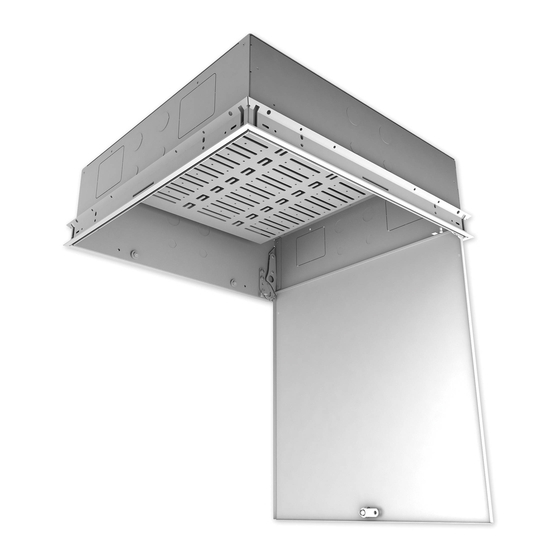
- Page 1 I N S T A L L A T I O N I N S T R U C T I O N S Ceiling Tile Storage Kit Spanish Product Description German Product Description Portuguese Product Description Italian Product Description Dutch Product Description French Product Description CMS490...
-
Page 2: Important Safety Instructions
WARNING: Exceeding the weight capacity can result in serious personal injury or damage to equipment! It is the installer’s responsibility to make sure the combined weight of all components and the CMS490 does not exceed 50 lbs (22.7 kg). - Page 3 Installation Instructions CMS490 DIMENSIONS 34.9 1.38 22.4 88.9 0.88 3.50 34.9 88.9 1.38 3.50 0.88 DIMENSIONS: [MILLIMETERS] INCHES LEGEND Tighten Fastener Drill Hole Apretar elemento de fijación Perforar Befestigungsteil festziehen Bohrloch Apertar fixador Fazer furo Serrare il fissaggio Praticare un foro...
-
Page 4: Tools Required For Installation
J (1) [Track clip - right] E (2) H (5) [Outlet box 10-32 x 3/8" 08-32 x 1" attachment plate] K (1) CMS490 Securement Kit KB (4) [Cable support] KA (4) 1/16" x 25’ [Wire cable] L (1) [CMS490] KC (4) KD (4) 1/4"... -
Page 5: Preparing For Installation
WireVice system. Preparing Framework Attach track clips [2 left (A), 2 right (B)] one at each corner of the CMS490 frame (N) using one 06-32 x 1/2" Phillips flat head screw (F) on each clip. (See Figure 1) (F) x 4... - Page 6 Examine ceiling structure (concrete, steel truss, or wood) above CMS490 frame (N) to identify four support cable anchor locations. Each location should be approximately (KC) 15° outside of support holes in CMS490 frame (N). Mark locations with pencil. (See Figure 4). 15° 1/4"...
- Page 7 Installing Electrical Box and Outlet Install Listed electrical box (not included) to outlet box attachment plate (J). Install the plate (J) with attached electrical box onto the CMS490 frame (N) using two 8-32 x 1/4" Phillips screws 5/32" (G). (See Figure 9) (KA)
- Page 8 Lower onto CMS490 frame, carefully lining up outlet box attached to CMS490 frame with opening in CMS490. (See Figure 11) Secure the CMS490 (L) to the CMS490 frame (N) using four 8-32 x 1" Phillips head screws (H), two on each side of the CMS490. (See Figure 11) Secure the outlet box attachment plate (J) to the CMS490 using one 8-32 x 1"...
-
Page 9: Grounding Instructions
Spaces in Accordance with Section 300.22(C) of the National Electrical Codes, 2008. Attach one of the grounding wires (M) using one 10-32 grounding nut (P) between the door and the CMS490 box at one of the points marked with grounding labels. (See Figure 12) -
Page 10: Adding Components
Open and lower door on CMS490. Component Loosen, but do NOT remove, four thumb nuts on tray component tray. (See Figure 14) Slide tray and lower to remove from CMS490. (See Figure 14) x 4 thumb nuts x 4 thumb nuts Figure 15 Component... - Page 11 Installation Instructions CMS490...
- Page 12 Europe A Franklinstraat 14, 6003 DK Weert, Netherlands P +31 (0) 495 580 852 F +31 (0) 495 580 845 Chief, a products division of Asia Pacific A Office No. 918 on 9/F, Shatin Galleria Milestone AV Technologies 18-24 Shan Mei Street...
Need help?
Do you have a question about the CMS490 and is the answer not in the manual?
Questions and answers