Table of Contents
Advertisement
Advertisement
Table of Contents

Related Manuals for Atlantic Aurea M Series


Summary of Contents for Atlantic Aurea M Series
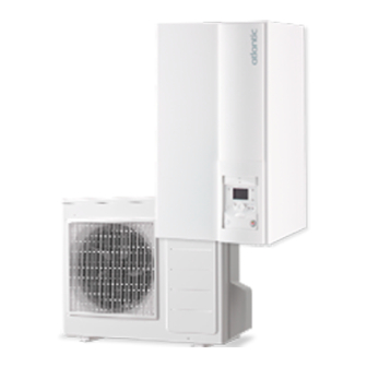
- Page 1 Heat pumps & boilers INSTALLATION Aurea M Air/water heat pump single service Monobloc system Outdoor unit AEYC-0639U-AT AEYC-1039U-AT1 AEYC-1039U-AT2 AEYC-1639U-AT Hydraulic unit 023227 U0618930_1883_EN_5 For professionals 22/02/2019 To be kept by the user for future reference...
- Page 2 ■ Installation and maintenance rules ■ Hydraulic connections The appliance must be installed and maintained by The connection must comply with good engineering an approved professional in accordance with the practices according to the regulations in force. prevailing regulations and code of practice. Reminder: Make the assembly seals according to good engineering practices in force for plumbing ■...
- Page 3 ■ Electrical connections • General remarks on electrical connections It is essential to maintain the phase-neutral polarity • Always check that the electric power supply is when making the electrical connections. switched off before works. Rigid wire is always preferable for fixed installations, •...
-
Page 4: Table Of Contents
Contents Presentation of the equipment Packing list ......6 Specifications ......7 Unpacking and reservations . - Page 5 Fault diagnostic Faults displayed on the hydraulic unit ..50 Information display ..... . . 54 Faults displayed on the outdoor unit .
-
Page 6: Presentation Of The Equipment
Presentation of the equipment ► Packing list - 1 package: Outdoor unit. - 1 package: Hydraulic unit and outdoor temperature sensor. Heat pump Outdoor unit Hydraulic unit Model Reference Model Reference Code Reference Code Aurea M 5 526900 Aurea 5 AEYC-0639U-AT 700125 Aurea M 8... -
Page 7: Specifications
► Specifications Model name Aurea Nominal heating performances (outdoor temperature/ initial temperature) Heat output +7°C/+35°C - Under-floor heating 5.00 8.00 10.00 16.00 -7°C / +35°C - Under-floor heating 3.55 7.10 8.00 12.50 +7°C / +55°C - Radiator 3.88 7.50 8.90 12.80 -7°C / +55°C - Radiator 2.91... - Page 8 ■ Outdoor unit Aurea 5 Circulating water Circulating water 15.3 return port return port R3/4(20A) Circulating water Circulating water 122.5 122.5 outgoing port outgoing port ■ Outdoor unit Aurea 8 & Aurea 10 75 70 Circulating water Circulating water outgoing port outgoing port R1(25A) R1(25A)
- Page 9 ■ Hydraulic unit Aurea M fig. 7 - Hydraulic unit dimensions in mm to secure the hydraulic Support unit. to detect the outdoor Outdoor sensor temperature to insulate the Insulating sleeves hydraulic connectors for condensate to be installed on the Elbow Filter valve evacuation...
- Page 10 ■ Outdoor unit Aurea 5 ■ Outdoor unit Aurea 8 & Aurea 10 ■ Outdoor unit Aurea 16 1 - Main board. 2 - Board. 3 - Terminal block. 4 - Safety valve. 5 - Bleed valve. 6 - Compressor. 7 - Circulation pump.
- Page 11 ■ Hydraulic unit Aurea M 1 - Electric box. 2 - Regulator / User interface. 3 - On/Off switch 4 - Bleed tap. 5 - Manometer 6 - Expansion vessel. 7 - Buffer (Electrical back-up optional). 8 - Manual drainer. 9 - Flow-meter.
-
Page 12: Operating Principle
► Operating principle The hydraulic unit has a regulator that controls the ■ Domestic hot water (DHW) operating principle* indoor temperature based on the measurement of the Two domestic hot water (DHW) temperatures may outdoor temperature, known as weather-dependent be set: comfort temperature (line 1610 at 55 °C) control. - Page 13 ...
-
Page 14: Location
Location ► Installing the outdoor unit ■ Outdoor unit Aurea 5 ▼ Installation precautions The outdoor unit must only be installed outdoors. If a shelter is required, it must have broad openings on all 4 walls and comply with the installation clearances. - Page 15 ▼ Positioning the outdoor unit The outdoor unit must be raised by at least 50 mm from the ground. In snowy regions, this height must be increased but must not exceed 1.5 m. Fasten the outdoor unit using screws and elastic tightening or toothed lock washers to prevent them from coming loose.
-
Page 16: The Hydraulic Unit
► the hydraulic unit ▼ Installation precautions ▼ Positioning the hydraulic unit - Secure the support (4 screws and plugs) to a flat, The choice of the position for installation is sturdy wall (not a light-weight partition) ensuring that particularly important insofar as any later it is correctly levelled. - Page 17 fig. 16 - Remove the panel - 17 - Aurea M / Installation / 1883 - EN...
-
Page 18: Hydraulic Connection
Hydraulic connection ► Rinsing the installation Before connecting the hydraulic unit to the installation, rinse the heating system correctly to eliminate the particles that could compromise the correct operation of the appliance. Do not use solvents or aromatic hydrocarbons (petrol, paraffin, etc.). -
Page 19: Heating Installation Volume
► Heating installation volume The installation's min. water volume must be respected. Install a buffer tank on the heating circuit return if the volume is lower than this value. In the case of an installation equipped with thermostat valves, you must ensure that this min. -
Page 20: Electrical Connection
Electrical connection Ensure that the general electrical power supply has been cut off before starting any repair work. The electrical installation must be conducted in accordance with the prevailing regulations. The electrical diagram of the hydraulic unit is detailed in fig. -
Page 21: Cable Section And Protection Rating
► Cable section and protection rating The cross sections of the cables are provided for information only and do not dispense the electrician from checking that these cross sections correspond to the requirements and satisfy the standards in force. ■ Power supply to outdoor unit Heat pump (HP) 230 V - 50 Hz electric power supply Connector cable... -
Page 22: Electrical Connections On The Outdoor Unit Side
► Electrical connections on the outdoor unit side ▼ Access to the connection terminals ■ Outdoor unit Aurea 5 - Remove the cover. Cable clamp Unscrew the cover (1 screw) Cables ■ Outdoor unit Aurea 8 & Aurea 10 & Outdoor unit Aurea 16 - Remove the cover. - Page 23 ▼ Heating cable (optional) - Locate the heating part (see fig. 21). Thermostat Thermostat - Place the thermostat at the bottom of the tank. - Run the bottom of the tank with the heating part of the Repère mark cable (make sure that the drain hole is covered by the heating part).
-
Page 24: Electrical Connections On The Hydraulic Unit Side
► Electrical connections on the hydraulic unit side ▼ Access to the connection terminals - Remove the front panel (2 screws) (fig. 16, page 17). - Open the power control box. - Make the connections according to the diagram fig. 22, page Do not fit the sensor wires and the power supply wires in parallel in order to avoid interferences due to the voltage surges in the power supply. - Page 25 ▼ Electrical backup (optional) ▼ Contract with the power supplier. - Connect the electrical supplies of electrical back-up to It is possible to control the HP's operation with the electrical panel ( see specific peak/off-peak and day / night contracts. fig.
- Page 26 ▼ Outdoor sensor ▼ Ambient sensor and/or central ambient unit (option) The Outdoor sensor is required for the correct operation of the heat pump. The ambient sensor (the central ambient unit) is optional. Consult the assembly instructions on the packaging of the sensor.
- Page 27 Hydraulic unit regulator Cable grommet Interface board Electricity supply terminal strip fig. 23 - Hydraulic module's electrical cabinet Shedding or EJP Délestage ou EJP (Peak Day Clear) (Effacement Jour de Pointe) Tarifds, day/night, peak/off-peak Tarifs, jour/nuit, HP/HC External fault Défaut externe Contact d'organe External component externe*...
-
Page 28: Start-Up
Start-up ► Configuration of the ambient - Engage the main isolator switch of the installation. sensor When first put into service (or in winter), to preheat the compressor, engage the main isolator switch To configure the ambient sensor and associate it to the of the installation (heat pump power supply) for adequate heating zone: several hours before the tests. -
Page 29: Heating Circulation Pump Speed Settings
► Heating circulation pump speed settings Main water pump in the heat pump has 3 levels of speed. Factory default value is Level 3. Select dip switch of DIP SW. on PCB(Terminal) to change the setting. ■ Outdoor unit Aurea 5, 8 & 10 ■... -
Page 30: Regulation Interface
Regulation interface ► The user interface, the central ambient unit (option) and the ambient sensor (option) fig. 27 - User interface Auto Auto °C fig. 25 - Central ambient unit T75/T78 fig. 26 - Radio room thermostat T55/T58 - 30 - Aurea M / Installation / 1883 - EN... - Page 31 Ref. Functions - Definition of the functions - Start: Production of DHW in function of the timer programme. Selecting the DHW operation - Stop: Production of the DHW stopped with antifreeze function of the Marche domestic water active. - Manual start button: Press the DHW button for 3 s (switches from "reduced"...
-
Page 32: Description Of The Display
► ► Description of the display Weather-dependent control The operation of the heat pump is controlled by the weather-dependent setpoint. The set temperature for the water in the heating circuit is adjusted according to the outdoor temperature. If there are thermostatic valves fitted to the installation, they must be opened fully or set higher than the normal value of the ambient temperature. - Page 33 Pente de la Heating curve 2.75 courbe de chauffe ° C slope Application PAC seule Heat pump application only 2.25 Radiateur classique Traditional radiator 1.75 Radiateur BT Low temperature radiator 1.25 (basse température) Radiateur dynamique Dynamic radiator 0.75 Underfloor heating Plancher chauffant 0.25 °...
-
Page 34: Regulation Menu
Regulation menu ▼ Setting parameters ▼ General - Selecting the desired level. Only the parameters accessible at the levels: - Scroll the list of menus. U - end user. - Selecting the desired menu. I - Commissioning - Scroll the function lines. S - Specialist. - Page 35 ► List of function lines Setting Basic Line Function Setting range or display increment setting Time of day and date Hours / minutes 00:00... 23:59 --:-- Day/Month 01:01... 31.12 --.-- Year 1900... 2099 ---- 25.03 Start summer time (Day / Month) 01:01...
- Page 36 Setting Basic Line Function Setting range or display increment setting Time program cooling, Circuit 1 (Only available when parameter 5711 is set to “2-pipe system”) Pre-selection (day / week) Mon-Sun, Mon-Fri, Sat-Sun, Mon-Sun Monday, ... , Saturday, Sunday In service phase (start) 00:00...
- Page 37 Setting Basic Line Function Setting range or display increment setting Holiday programs, Circuit 1 (the heating mode must be on "AUTO") Preselection Period 1 to 8 Period 1 Date of start of holidays (day/month) 01:01... 31.12 --.-- --.-- Date of end of holidays (Day/Month) 01:01...
- Page 38 Setting Basic Line Function Setting range or display increment setting Start increasing the reduced operation -30... 10 °C 1 °C End of increase in reduced operation -30... 10 °C 1 °C -5 °C Raising of mixing valve 0... 50 °C 1 °C 0 °C 240 s...
- Page 39 Setting Basic Line Function Setting range or display increment setting Flow temp setp at OT° 25°C 6... 35 °C 0.5 °C 20 °C Starting cooling temperature setting for an outdoor temperature of 25 °C. Flow temp setp at OT° 35°C 6...
- Page 40 Setting Basic Line Function Setting range or display increment setting Flow temp setp min OT° 25°C 6... 35 °C 0.5 °C 18 °C The lowest starting temperature for cooling for an outdoor temperature of 25 °C. Flow temp setp min OT° 35°C 6...
- Page 41 Setting Basic Line Function Setting range or display increment setting 1050 Room influence 1 %... 100 % 50 % If the installation is fitted with a room thermostat: This function enables you to choose the ambient temperature's influence on the setting. If no value is entered, the setting is made based on the temperature control.
- Page 42 Setting Basic Line Function Setting range or display increment setting 1218 Summer comp start at OT° 20... 50 °C 1 °C 26 °C The comfort setting (1202) is increased in line with the outdoor temperature rising above this reading. 1219 Summer comp end at OT°...
- Page 43 Setting Basic Line Function Setting range or display increment setting 1640 Anti-legionnella function Off, Periodic (according to the setting for line), Fixed day of the week (according to the setting for line 1642) 1641 Frequency of anti-legionella cycle 1 to 7 1 day 1642 Anti-legionella cycle operation day...
- Page 44 Setting Basic Line Function Setting range or display increment setting Energy meter 3113 Energy brought in Cumulation of total consumed electrical energy. Electrical energy consumed = Electrical energy absorbed by outdoor unit + electric energy absorbed by the heating electrical backup and / or DHW electrical backup (if installed). 3124 Energy brought in heating 1 (N - 1) 3125...
- Page 45 Setting Basic Line Function Setting range or display increment setting 3197 Compressor electrical power 0.1...60 0.1 kW See table below 3197 parameter setting according to outdoor unit used Heat pump Outdoor Unit Model Parameter 3197 Aurea M 5 Aurea 5 1.28 Aurea M 8 Aurea 8...
- Page 46 Setting Basic Line Function Setting range or display increment setting 5981 Input action direction EX1 Normal closed, Normal opened Normal opened 5982 EX2 input function E5 electricity reduced tariff 0: Without, 1: E6 elec. reading forced stop 2: E5 electricity reduced tariff, 3: ---, 4: Evapor. overload E14, 5: Evaporat.
- Page 47 Setting Basic Line Function Setting range or display increment setting 7141 Assist mode Off, On Off: Heat pump functions normally (with boosters if necessary). On: Heat pump uses the electric boost system or the boiler connection. Use the “On” position only in Assist mode or Test mode:may result in high power bills. 7142 Backup service operating type Manually, Automatically...
- Page 48 Setting Basic Line Function Setting range or display increment setting State 8000 Heating circuit 1 status 8001 Heating circuit 2 status 8003 DHW status 8004 Cooling circuit 1 status 8006 HP status 8022 Stupplementary source status 8025 Cooling circuit 2 status Diagnostics producer 8400 State of compressor 1...
- Page 49 Setting Basic Line Function Setting range or display increment setting 8756 Cooling flow temperature 1 0... 140 °C 1 °C Cooling flow temperature setpoint 1 8760 Heating circuit 2 circulator Off, On 8761 Heat circ mix valve 2 open Off, On 8762 Heat circ mix valve 2 close Off, On...
-
Page 50: Fault Diagnostic
Fault diagnostic Depending on whether the fault is on the heat pump or the hydraulic module, the fault may be indicated by the hydraulic unit's digital display or the outdoor unit's display. ► Faults displayed on the hydraulic unit The faults or breakdowns of the hydraulic unit are reported on the display unit of the user interface. -
Page 51: Faults Displayed On The Outdoor Unit
► Faults displayed on the outdoor unit The faults or breakdowns on the outdoor unit are indicated by the outdoor unit's main board display. The display indicates the last error code. Main board "RESET" button Display Press the “RESET” button to reset the fault. Press the “RESET”... - Page 52 Error Error contents, Error Verification Breakdown maintenance codes Location of the error reset Check that the air flows freely in and out Check the installation's environment Abnormal operation in (blockage of the air inlet and outlet) If there is excess gas, collect the cooling gas first of all, under/overload Check the excess gas then reload with the recommended quantity of gas...
- Page 53 Error Error contents, Error Verification Breakdown maintenance codes Location of the error reset Fuse CF7 250V T3.15A If CF7 is burnt, replace the fan motor and the CF7 fuse If CF7 is not burnt, check the fan motor's power supply Upper fan motor Check the electrical continuity voltage...
-
Page 54: Information Display
Error Error contents, Error Verification Breakdown maintenance codes Location of the error reset Fuse CF2 If CF2 is burnt, replace the fuse, test the 4-channel 0639U : 250V T3.15A Test the CF1 fuse solenoid valve and the reheater 1039U : 250V T3.15A 1639U : 250V T5A 4-channel valve Test the solenoid valve... -
Page 55: Maintenance
Maintenance Ensure that the general electrical power supply has been cut off before starting any repair work. ► Hydraulic checks Warning :If frequent refills are required it is U0629273-A essential that you look for any leaks. If you need to fill up and reset the pressure, check the type of fluid originally used. -
Page 56: Appendices
Appendices ► Overall hydraulic layout ■ Configuration 1: 1 heating circuit and DHW tank (DHW kit External) - 56 - Aurea M / Installation / 1883 - EN... - Page 57 ■ Configuration 1: 1 heating circuit and DHW tank (DHW kit Internal) - 57 - Aurea M / Installation / 1883 - EN...
- Page 58 ■ Configuration 2: 2 heating circuits. - 58 - Aurea M / Installation / 1883 - EN...
- Page 59 ■ Configuration 2: 2 heating circuit and mixed DHW tank (DHW kit External) - 59 - Aurea M / Installation / 1883 - EN...
-
Page 60: Electrical Cabling Diagrams
► Electrical cabling diagrams fig. 32 - Aurea 5 and Aurea 8 & Aurea 10 outdoor unit electrical cabling - 60 - Aurea M / Installation / 1883 - EN... - Page 61 fig. 33 - Aurea 16 outdoor unit electrical cabling - 61 - Aurea M / Installation / 1883 - EN...
- Page 62 Carte Interface / Interface board 3 2 1 3 2 1 1 2 3 Carte Extension/ Additional board X100 Départ / Flow sensor Kit 2 circuits / 2 circuits kit Contact d'organe externe / FUSE 250V/6.3A External device connection Interface Utilisateur / Délestage /Power shedding User Interface...
- Page 63 ...
-
Page 64: Start Procedure
Start procedure Before switching on the hydraulic unit : - Check the electrical cabling. - Check that the refrigeration circuit is filled with gas. - Check the hydraulic circuit's pressure (1 to 2 bars), check that the heat pump is drained, along with the rest of the installation. - Page 65 ▼ Start-up Non-compliant • Starting up ( see chapter “ Start-up”, page 28 and “List of function lines”, page 35) Push in the installation's general circuit breaker (outdoor unit power ) 2 hours before the tests => Compressor pre-heating. Push in the on/off switch => Few seconds' initialisation. Operation of the heating circulator The outdoor unit starts after 4 min.
-
Page 66: Configuration File
► Configuration file Parameter Item Setting Menus Parameter Item Setting Menus Preliminary settings Boiler backup language 3700 OT.switch-on authoris. inter. Use addit. gen. hour / minutes 3705 swith-off delay time and addit. gen. date Miscellaneous day / month time and 6420 H33 input function configuration... -
Page 67: Instructions For The User
► Start-up data sheet Worksite Installer Serial No. Serial No. Outdoor unit Hydraulic unit Model Model Type of refrigerant Refrigerant charge Checks Voltages and currents in operation on the outdoor unit Compliance with positioning distances Condensate evacuation OK Electric connections / connections tightened Icomp Hydraulic network on hydraulic unit Underfloor heating... - Page 68 Date of commissioning: atlantic-comfort.com Société Industrielle de Chauffage Address of your heating installer or customer service. SATC - BP 64 - 59660 MERVILLE - FRANCE This equipment complies with: - Low Voltage Directive 2014/35/EC in accordance with NF EN 60335-1, NF EN 60335-2-40, NF EN 60529, NF EN 60529/A2 (IP) standards,...
Need help?
Do you have a question about the Aurea M Series and is the answer not in the manual?
Questions and answers