Table of Contents
Advertisement
Quick Links
Advertisement
Chapters
Table of Contents

Related Manuals for Atlantic Alfea Excellia A.I. 024114


Summary of Contents for Atlantic Alfea Excellia A.I. 024114
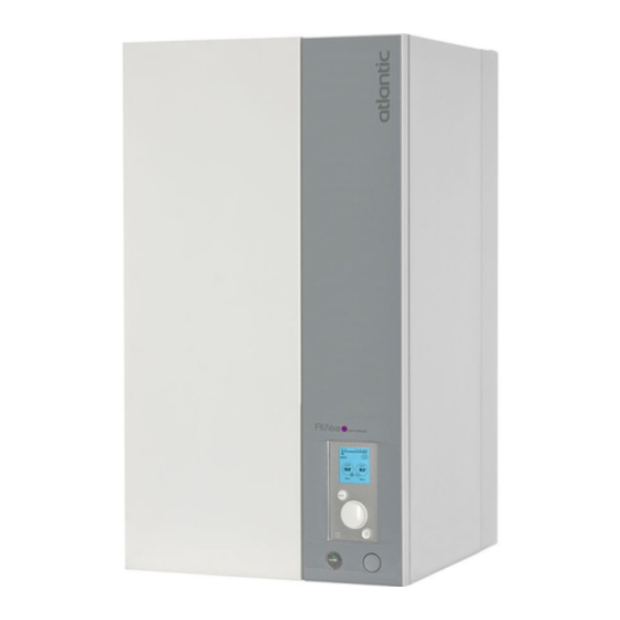
- Page 1 Heat pumps & boilers INSTALLATION Alféa Excellia A.I. Air/water heat pump split 1 service Outdoor unit WOYG112LHT WOYG140LCTA WOYK112LCTA WOYK140LCTA WOYK160LCTA Hydraulic unit 024114 024115 U0611757_1876_EN_14 For professionals. 02/02/2023 To be kept by the user for future reference...
- Page 2 ■ Hydraulic connections ■ Installation and maintenance rules The connection must comply with industry standard The appliance must be installed and maintained practice according to current regulations. by an approved professional in accordance with current regulations and codes of practice. Remember: Seal everything...
- Page 3 ■ Electrical connections • Connecting to screw terminals The use of ring, spade or blade terminals or • Before any maintenance operation, ensure caps is prohibited. that the general power supply is switched off . - Always select wire that complies with current •...
-
Page 4: Table Of Contents
This appliance must be installed by qualifi ed personnel holding a certifi cate of competence in the handling of refrigerants. Contents Description of the equipment Packing ....... . . 6 Operating Range . - Page 5 Controller Menu Menu Structure ......52 System status ......60 Installed options .
-
Page 6: Description Of The Equipment
Description of the equipment ► ► Packing Defi nitions - Split: The heat pump consists of two elements • 1 package: Outdoor unit. (an outdoor unit to be installed outdoors and a hydraulic • 1 package: Hydraulic unit and outside temperature unit to be installed inside the dwelling). -
Page 7: General Characteristics
► General characteristics Model name Alféa Excellia A.I. tri 11 tri 14 tri 16 Rated heating performances (outdoor temp. / fl ow temp.) Heat output +7°C/+35°C - Underfl oor heating system 10.80 13.50 10.80 13.00 15.17 -7°C/+35°C - Underfl oor heating system 10.38 11.54 10.38... - Page 8 ■ Outdoor Unit, Excellia A.I. 11 and 14 Overfl ow hole 4 holes Orifice d’écoulement (Ø 20) 4 trous Ø 12 Bottom view Vue de dessous 1290 3/8” 5/8” Front view Vue de face Side view Vue de coté Top view Vue de dessus ■...
- Page 9 ■ Hydraulic unit Heating fl ow Heating return ø M 26x34 ø M 26x34 Front view Side view Space requirements of the hydraulic unit, see page 20. fi g. 2 - Dimensions in mm Elbow for attaching hydraulic Bracket unit. Plugs (x2) for condensate evacuation.
- Page 10 Variable pressure Constant pressure mCE (1 mbar = 10 mmCE = 100 Pa) mCE (1 mbar = 10 mmCE = 100 Pa) Constant speed mCE (1 mbar = 10 mmCE = 100 Pa) fi g. 6 - Available hydraulic pressures and fl ow rates HP return sensor.
- Page 11 10000 - Compressor. - Discharge. - Condensation. - Expansion valve. 1000 - Outdoor unit. - Evaporator inlet. -20 -10 0 10 20 30 40 50 60 70 80 90 100 110 120 130 Temperature °C fi g. 7 - Ohmic sensor values (Outdoor unit) alfea excellia A.I.
-
Page 12: Description
► Description ■ Alféa Excellia A.I. 11 and 14 ■ Alféa Excellia A.I. tri 11 , 14 and 16 Key: High performance and low noise impeller. Electrical motor with variable "inverter" operation. "Inverter" control unit. Check lights and buttons. Connection terminal blocks (power supply and interconnection). - Page 13 11 3 Key: 1 - Electric box. 9 - Drain valve. 2 - Controller / User interface. 10 - Safety valve. 3 - Start/stop switch. 11 - Pressure gauge. 4 - Heating circulation pump. 12 - Automatic bleeder valve. 5 - Heating fl ow. 13 - Expansion vessel.
-
Page 14: Operating Principle
► Operating principle • Control functions The heat pump transmits the energy contained in the surrounding air into the dwelling to be heated. - The heating circuit's fl ow temperature is controlled by the temperature control. The heat pump consists of four main elements, in which a refrigerant (R410A) circulates. - Page 15 • Domestic hot water (DHW) operating principle Two domestic hot water (DHW) temperatures can be If the contract signed with the energy provider includes set: comfort and reduced. a day/night tariff , the electrical backup is subject to the supplier’s power tariff and the comfort temperature may The default DHW program is set to the comfort only be reached at night.
-
Page 16: Installation
Installation ► Installation of refrigeration connections Bend the pipes into position and make holes for them through the fl oor or walls either with their protective caps in place or after brazing. Keep the protective caps in place or ends brazed until the appliance is commissioned. -
Page 18: Installation Of The Outdoor Unit
► Installation of the outdoor unit ▼ Installation precautions • Water may fl ow out of the outdoor unit when it is The outdoor unit must only be installed operating. Do not install the unit on a paved terrace; outside. If a shelter is required, it must have choose a well-drained location (e.g. - Page 19 • The surface on which the appliance is installed must: - Be permeable (soil, gravel, etc.). - Support its weight easily. - Allow a solid fastening base, - Not transmit any vibration to the dwelling. Anti-vibratory blocks are available as an option. •...
-
Page 20: Installation Of The Hydraulic Unit
► Installation of the hydraulic unit - To avoid condensation inside the condenser, remove ▼ Installation precautions the refrigeration circuit caps only when making the refrigeration connections. • Choose the location of the appliance after discussion with the client. - If the refrigeration connection is only performed at the end of the installation, make sure that the refrigeration •... - Page 21 fi g. 16 - Removing the casing alfea excellia A.I. / Installation / 1876 - EN - 21 -...
-
Page 22: Refrigeration Connections
Refrigeration connections This appliance uses refrigerant R410A. • Other remarks Comply with the legislation on handling of refrigerants. - After each maintenance operation on the refrigeration circuit and before fi nal connection, take care to put ► Rules and precautions the caps back in position to avoid any pollution of the refrigeration circuit. - Page 23 ▼ Creating the fl arings - Cut the pipe to an appropriate length with a pipe-cutter without damaging it. - Carefully deburr it, holding the pipe pointing downward to avoid introducing fi lings into the pipe. - Remove the fl ared connection nut situated on the valve to be connected and slide the pipe into the nut.
- Page 24 HP model Alféa Excellia A.I. single and 3 phase liquid Outside unit connections 5/8" 3/8" Diameter: (D1) 5/8" (D2) 3/8" Minimum length (L) Refrigeration Maximum length* (L) connections Maximum length** (L) Maximum Height Difference** (D) Hydraulic unit connections 5/8" 3/8" * : Without additional fi...
-
Page 25: Checks And Connection
► Checks and connection The refrigeration circuit is very sensitive to dust and humidity: check that the area around the connection is clean and dry before Liaison removing the plugs protecting the refrigeration connection Azote Nitrogen connectors. Indicated blowing value: 6 bar for minimum 30 seconds for connection of 20 m. -
Page 26: Filling The Installation With Gas
► Filling the installation with gas This operation is reserved for installers familiar with the legislation for handling refrigerants. Creating a vacuum with a calibrated vacuum pump is essential (see APPENDIX 1). Never use equipment used previously with any refrigerant other than a HFC. Only remove the refrigeration circuit caps when performing the refrigeration connections. - Page 27 ▼ Creating a vacuum ▼ Seal test - Remove the protective plug (B) from the fi lling hole The triple evacuation method (APPENDIX 2) (Schrader) in the gas valve (large diameter). is strongly recommended for any installation - Connect the high pressure hose from the Manifold to and especially when the outdoor temperature the fi...
- Page 28 ▼ Filling with gas ▼ Additional fi lling 50 g of R410A If additional fi lling is required, do it before for every additional 1 metre fi lling the hydraulic unit with gas. Refer to Length of the paragraph "Additional fi lling", page 15 m 20 m max.
- Page 29 ▼ Recovering the refrigerant in the outdoor unit Before performing any maintenance, make sure that all power supplies have been cut off . Stored energy: after cutting off the power supplies, wait for 1 minute before accessing the internal parts of the equipment. Perform the following procedures to collect the refrigerant.
-
Page 30: Hydraulic Connections
Hydraulic connections ► Connecting the hydraulic unit to the heating circuit ▼ Flushing the installation Before connecting the hydraulic unit to the installation, rinse out the heating system correctly to eliminate any particles that may aff ect the appliance's correct operation. -
Page 31: Filling And Bleeding The Installation
▼ Volume of the heating system You must maintain the minimum installation water volume. Install a buff er tank on the return from the heating circuit in case the volume is lower than this value. Where the system is fi tted with one or more thermostatic valves, you must ensure that this minimum water volume is able to circulate. -
Page 32: Heating Circulation Pump Speed Settings
► Heating circulation pump speed settings Default LED LED Défaut Mode Display Affichage Mode (Variable pressure, (Pression variable, Constant pressure, Pression constante, Vitesse constante) Constant speed) 1sec 1sec Button Bouton Affichage Vitesse Speed Display (I, II, III) (I, II, III) fi... - Page 33 Variable pressure The circulation pump varies the water pressure depending on the fl ow rate. Recommended for an installation fi tted with radiators (particularly any system with thermostatic valves or zone solenoids). Q/m /h Constant pressure The circulation pump maintains a constant water pressure whatever the fl ow rate. Recommended for an installation with constant pressure drops such as an underfl...
-
Page 34: Electrical Connections
Electrical connections Before any maintenance operation, ensure that the general power supply is switched off . Electrical installation must be performed in accordance with current regulations. The electrical diagram for the hydraulic unit is shown on fi g. 53, page Room sensor A78 (battery/option) Room sensor A59 (battery/option) Outside sensor... -
Page 35: Cable Dimensions And Protection Rating
► Cable dimensions and protection rating These cable dimensions are provided for information purposes only and do not exempt the installer from checking that these dimensions match requirements and comply with current standards. • Outdoor Unit Power Supply Single phase heat pump Electricity supply 230 V - 50 Hz Max. -
Page 36: Electrical Connections On The Single Phase Outdoor
► Electrical connections on the single phase outdoor unit side Access to connection terminals: - Remove the front plate. Remove the screws and front - Make the connections according to the diagram(s) panel. fi g. 41, page Terminal Remove the screws and push downwards Terminal Remove... -
Page 37: Side
► Electrical connections on the 3 - Use cable clamps to prevent any power cables from being disconnected accidentally. phase outdoor unit side - Fill in the space where the cables enter the outdoor Access to connection terminals: unit with the insulating plate. - Remove the front plate. -
Page 38: Electrical Connections On The Hydraulic Unit Side
► Electrical connections on the hydraulic unit side ▼ DHW tank with electrical backup heating Access to connection terminals: (option) - Remove the front panel (2 screws). - Open the power control box. If the installation is fi tted with a DHW tank with electrical backup heating: - Make the connections according to the diagram (fi... - Page 39 ▼ External control It is possible to control the changeover from "Heating Mode" to "Cooling Mode" via an "external control unit". Function not compatible with : - Dual circuit kit - Room sensors A59, A75 et A78 Parameter setting HP confi guration Tariff...
- Page 40 Single phase model Hydraulic unit Single phase outdoor unit 1 2 3 towards external component contact* green/yellow brown blue Interconnection between outdoor unit and hydraulic unit Power supply for Electricity supply Electrical backup single phase 230 V single phase 230 V 3 phase model Hydraulic unit 3 phase outdoor unit...
- Page 41 Power supply terminal block HP controller Safety thermostat Power Relay for electric backup Interface Board Terminal Cable grommets (power) Cable grommets (sensors) fi g. 43 - Description of the single phase hydraulic unit's electrical control box Power supply terminal block HP controller Safety thermostat Static relay for electric backup...
-
Page 42: Outside Sensor
► ► Outside sensor Room sensor (option) The outside sensor is required for correct operation of The room sensor (room unit) is optional. the heat pump. Please see the fi tting instructions on the sensor’s Please see the fi tting instructions on the sensor’s packaging. - Page 43 Power limitation or (Energy Demand Reduction) Tariff s, peak times/off - peak times, PV External fault External component contact* (faults, power limiter, electricity meter) Outside sensor ** Typass ATL ** Room sensor A59 (if cabled) ** Room sensor A75 ** If the control device does not provide a potential-free contact, the contact must be relayed to create an equivalent wiring. In any case, refer to the instructions for the external components (power limiting device, electricity meter, etc.) to create the wiring.
- Page 44 Commissioning - Close the installation's main circuit breaker. - Press the heat pump's Start/Stop button. Upon initial start-up (or in winter), to preheat the To ensure that inputs EX1, EX2 and EX3 operate compressor, engage the installation's main circuit correctly: Check that the electricity supply's breaker (outdoor unit power supply) several neutral phase polarity has been respected.
- Page 45 Easy Start 2nd circuit kit - If the installation covers 2 zones, set "2nd circuit kit" to "Yes". Easy Start Emitters type Area 1 (Direct circuit) - Choose the radiator type for each zone: Low temp. radiator / Heat. fl oor system / Dynamic Radiators / Radiators. Low temp.
-
Page 46: User Interface
Controller Interface ► User Interface 15:23 7 September 2017 15:23 7 September 2017 12° 12° 21,5 21.5 19.5 19,0° 19,0° 19,0° Area 1 Area 2 MENU MENU 1 heating Circuit version 2 heating circuit version + domestic hot water (DHW) + domestic hot water (DHW) N°... -
Page 47: Display Description
► Display Description 15:23 7 September 2017 12° 21.5 19.5 19,0° 19,0° Area 1 Area 2 N° Symbols Defi nitions N° Symbols Defi nitions Mode 15:23 Time Comfort Date 7 September 2017 Manual (exemption) Temperature measured by the room 21.5 sensor* 19,0°... -
Page 48: Installer Menu
► Installer Menu To access the Installer Menu, press and hold the MENU button and turn the knob a quarter turn to the right. To return to the User Menu, repeat the same operation. MENU fi g. 46 - Installer Menu ►... -
Page 49: Modifying Settings
► Modifying Settings • Turn the knob to highlight the setting you wish to change. MENU • Press the knob to accept the change. • Turn the knob to adjust the setting. Installed options • Press the knob to accept your choice. Hydraulic confi... -
Page 50: Temperature Control
► Temperature control The heat pump's operation is subject to the temperature control. The heating circuit water temperature setpoint is adjusted according to the outdoor temperature. If there are thermostatic valves on the installation, these must be fully open or set higher than the normal temperature setpoint. - Page 51 Pente de la 2.75 Heating curve gradient courbe de chauffe ° C 2.25 Standard radiator Radiateur classique 1.75 Radiateur BT With boiler connection Low temperature radiator Application relève de chaudière 1.25 (basse température) Heat pump application only Application PAC seule Dynamic radiators Radiateur dynamique 0.75...
-
Page 52: Controller Menu
Controller Menu ► Menu Structure Installed options page 52 Hydraulic confi guration Heating Control / Temperature control Temperature control Comfort optimisation page 53 ECO mode limitation Setting setpoint T° Time programming General Confi guration Time programming Setting setpoint T° Anti-legionella management HP confi... -
Page 53: Installed Options
Installed options ► Installed options Installed options are confi gured during commissioning (see page 44). However, you can modify them by accessing the "Installed Options" menu. Name of Appliance - Choose the appliance's power. Installed options Electrical backup Name of Appliance -- KW - Choose the electrical backup power. - Page 54 Hydraulic confi guration Area 1 Control / Temperature control Temperature control Choose the temperature control to adjust: "Heating". Two methods for adjusting the temperature control are available: fl ow temperature or gradient control. ● Control using fl ow temperature - Set "Room T° infl uence" then select "Advanced settings". - Set "Display"...
- Page 55 Hydraulic confi guration Area 1 Control / Temperature control Comfort optimisation Area 1 Comfort optimisation "Accelerated decrease": ON / Stop. Accelerated decrease Stop "ECO / Comfort switchover" Anticipates time needed to reach the comfort setpoint. Max anticipation "Comfort / ECO switchover" Anticipates time needed to switch from comfort setpoint ECO / Comfort switchover 03:00 h to ECO setpoint.
- Page 56 Hydraulic confi guration Area 1 Time programming - Choose "Heating" or "Cooling" as well as the appropriate zone by accessing the menu: "Programming" > "Heating" / "Cooling" > "Area 1" / "Area 2". - Select the day. - Adjust the Comfort period start and end times. If 2 or 3 Comfort periods are not required, click on "--:--".
- Page 57 Hydraulic confi guration Hot water ▼ Hot Water (HW) General Confi guration DHW Circuit Confi guration Comfort T° charge DHW program + off -peak hours "Comfort T° charge": DHW program + off -peak hours / Off -peak hours / Permanent. Electrical back-up power: 0.1 to 10 KW.
-
Page 58: Heat Pump Confi Guration
HP confi guration ► Heat Pump Confi guration ▼ Heat Pump Compressor confi guration "Minimum shutdown time": 0 mins... 120 mins. Compressor confi guration "Max HP T°": 8°C... 100°C. "Post-circulation": 10 secs... 600 secs. Minimum shutdown time 8 mins "Power shedding operating": Automatic, When needed. Max HP T°... - Page 59 HP confi guration Tariff input confi guration Heat Pump Tariff input confi guration Power shedding + Type of use "Type of use": Power shedding + Off -peak hours / Smartgrid / EXT control. Off-peak hours "EX1: function activation": 230V / 0V. EX1: function activation 230V "EX2: function activation": 230V / 0V.
-
Page 60: System Status
System status ► System status Active functions The "Active Functions" page tells you which services are operating and allows you to change their status. Active functions Indoor comfort Heating - "Indoor comfort": Heating / Cooling / Stop. Area 1 Start - "Area 1"... -
Page 61: Domestic Hot Water (Dhw)
System status Errors history Errors history 10/09/2016 Error Outside sensor, Flow sensor Flow sensor 10/09/2016 Error 44: Return sensor HP, 50: DHW sensor 1, 60: Room sensor 1, 65: Room sensor 2, 09/09/2016 Error 83: BSB short-circuit, 127: Legionella temp, 212: Internal comm failure, 441: BX31 no function, 09/09/2016 Error 442: BX24 no function, 443: BX33 no function, 444: BX34 no function, 369: External,... -
Page 62: Auxiliary Functions
Auxiliary functions ► Auxiliary functions Floor drying - Choose the zone. Area 1 fl oor drying - Choose the "Drying type": Stop / Automatic / Manual. Drying type Stop • Automatic Drying Flow T° setpoint 25°C Max fl ow T° 18 1 Automatic Drying •... - Page 63 Auxiliary functions Relay test - "HP circulation pump": ON / ---- - "Elec. backup 1": ON / ---- Relay test - "Area 2 circulation pump": ON / ---- HP circulation pump ---- Elec. backup 1 ---- - "Mixing valve": Open / Close / ---- Area 2 circulation pump ---- - "DHW valve": DHW / ----...
-
Page 64: Settings
Settings ► Settings Date and time Settings Date and time Monday September 2016 To set the appliance's date and time, access the menu: "Settings" > "Date and Time". 09: 45 Summer / winter time Automatic Modify Validate Language Settings Language To set the appliance's language, access the menu: English "Settings"... - Page 65 Settings Advanced/simplifi ed menu Two display modes for menus and appliance functions are available: - Advanced menu: - The appliance follows the time programming defi ned in paragraph "Time programming", page 56. - Simplifi ed menu*: - The appliance operates at a constant temperature set directly by the user. - Some functions are no longer accessible.
- Page 66 Settings Areas name Settings Circuits name You can customise the zone names from the menu: Rename Zone 1 in "Settings" > "Areas name". Available names: "Area 1" / "Area 2" / "Day area" / "Night area" / "1st fl oor" / "Lounge" Rename Zone 2 in / "G.
- Page 67 Settings Software versions Software version HMI: xxxx xxxx xxxx xxxx Show the display and controller software versions. Controller: RVS21 - 85.002.030 Some settings (or menus) might not be displayed. They are dependent on the installation's confi guration (and installed options). alfea excellia A.I.
-
Page 68: Easy Start
Easy Start ► Easy Start Easy Start - Turn the knob to choose the language. English - Press the knob to accept. Easy Start Monday September 2016 - Turn the knob to adjust the date. Press the knob to accept. - Repeat this operation for the month, year, hours and minutes. - Page 69 Easy Start Emitters type Area 1 (Direct circuit) - Choose the radiator type for each zone: Low temp. radiator Low temp. radiator / Heat. fl oor system / Dynamic Radiators / Radiators. Easy Start Cooling - If the installation is fi tted with cooling fzunction, choose the zone(s): None / Area 1 / Area 2 / Area 1 and 2.
-
Page 70: Basic Hydraulic Layout
Basic Hydraulic Layout ■ Confi guration 1: 1 heating circuit - 70 - alfea excellia A.I. / Installation / 1876 - EN... - Page 71 ■ Confi guration 1: 1 heating circuit and mixed hot water tank alfea excellia A.I. / Installation / 1876 - EN - 71 -...
-
Page 72: Electrical Cabling Plans
Electrical Cabling Plans Option (connector) Control board (Inverter) Pressure sensor See the technical manual Temperature sensor. Compressor Temperature sensor. Outdoor Temperature sensor. Evaporator Temperature sensor. Discharge Expansion Fuse valve coil Temperature sensor. Radiator F4 T 5A - 250 V Temperature sensor. Evaporator centre Main Expansion... - Page 73 Expansion Solenoid coil valve solenoid coil Temperature sensor. Control board Expansion valve (Inverter) Temperature sensor. Evaporator centre Temperature sensor. P.F.C. radiator Temperature sensor. Discharge Temperature sensor. Evaporator outlet Compressor Temperature sensor. Condenser Outdoor Temperature board sensor. Temperature sensor. "Inverter" Compressor radiator Pressure sensor Reactor fan...
- Page 74 FUSE 250V/3.15A Condensation Sonde Condensation/ Condensation Sensor sensor OPTION 2 CIRCUITS 2 circuit option 2 circuits option 1 2 3 4 External Contact d'organe externe component contact External device connection FUSE 250V/6.3A Power limitation Délestage / Power shedding Tarifs HP/HC, PV Tariff...
- Page 75 FUSE 250V/3.15A Condensation Sonde Condensation/ Condensation Sensor sensor OPTION 2 CIRCUITS 2 circuit option 2 circuits option 1 2 3 4 External Contact d'organe externe component contact External device connection FUSE 250V/6.3A Power limitation Délestage / Power shedding Tarifs HP/HC, PV Tariff...
-
Page 76: Fault Diagnosis
Fault Diagnosis 15:23 7 September 2017 12° --,- If a fault occurs, the error number appears on the welcome screen. 24,0° To obtain the error's designation, select it using the knob. Error XXX Error In the event of an error originating in the outdoor unit, the user interface displays error code "370: Thermodynamic Generator"... -
Page 77: Faults In The Outdoor Unit
► Faults in the Outdoor Unit Outdoor Unit Interface Board Board Error Error designation Green Off Serial communication error UART communications error Hydraulic unit heat-exchange thermistor error Inverter error Active fi lter error, PFC error Discharge thermistor error Compressor thermistor error Heat-exchange thermistor error (centre) Heat-exchange thermistor error (outlet) Outdoor thermistor error... -
Page 78: Maintenance Of The Installation
Maintenance of the installation Before any maintenance operation, make sure that the general power supply is switched off . ► ► Hydraulic checks Checking the outdoor unit - Remove any dust from the exchanger, if necessary, If frequent refi lls are required it is absolutely while making sure not to damage the blades. -
Page 79: Other Maintenance
Other maintenance ► ► Emptying the hydraulic unit Distribution valve - Remove the front panel of the hydraulic unit. If the installation is fi tted with a hot water tank. - Open the drain plug, Ensure the distribution valve is fi tted in the correct direction. -
Page 80: Quick-Start Procedure
Quick-start procedure Before switching on the hydraulic unit: • Check the electric wiring. • Check the refrigeration circuit and make sure the it has been gassed. • Check the hydraulic circuit's pressure (1 to 2 bar), check that the heat pump has been bled, along with the rest of the installation. - Page 81 ▼ Starting-up Not compliant Quick Start Procedure (see chapter " Controller Menu", page 52) Close the installation's main circuit breaker (outdoor unit power supply) 2 hours before testing => Preheating of the compressor. Press the On/Off Switch => Initialisation takes several seconds. Operation of the heating circulation pump.
-
Page 82: Commissioning Technical Datasheet
► Commissioning technical datasheet Site Installer Serial N Serial N Outdoor unit Hydraulic unit Model Model Refrigerant type Refrigerant load Checks Operating voltage & current on outdoor unit Compliance with positioning distances L/N or L1/N Condensate evacuation correct L2/N Electric connections / connections tightness L3/N No GAS leaks (unit ID N L/T or L1/T... - Page 83 Instructions for the end user Explain to the user how his installation operates, in particular the functions of the room sensor and the programmes accessible to them via the user interface. Emphasise that a heated fl oor has signifi cant inertia and that therefore any adjustments must be made gradually.
- Page 84 Commissioning date: atlantic-comfort.com Société Industrielle de Chauffage Address of your heating installer or customer service. SATC - BP 64 - 59660 MERVILLE - FRANCE This equipment complies with: - Low Voltage Directive 2014/35/EC in accordance with NF EN 60335-1, NF EN 60335-2-40, NF EN 60529, NF EN 60529/A2 (IP) standards,...
Need help?
Do you have a question about the Alfea Excellia A.I. 024114 and is the answer not in the manual?
Questions and answers