Table of Contents
Advertisement
Indice - Index - Index - Inhaltsverzeichnis - Indice - Indice
ITALIANO
ENGLISH
FRANÇAIS
DEUTSCH
ESPAÑOL
PORTOGUÊS
Smontaggio - Disassembly - Demontage
Abmontierung - Desmontaje - Desmontagem
Regolazioni - Setting - Reglages
Einstellungen - Regulaciones - Regulações
1
1
Pag. - Page
Page - Seite
Pag. - Pag.
3
49
95
141
187
233
279
285
Code 931 - 065 - 000 (rev. 0525)
Advertisement
Table of Contents

Related Manuals for Faema X2 Granditalia


Summary of Contents for Faema X2 Granditalia
- Page 1 Indice - Index - Index - Inhaltsverzeichnis - Indice - Indice Pag. - Page Page - Seite Pag. - Pag. ITALIANO ENGLISH FRANÇAIS DEUTSCH ESPAÑOL PORTOGUÊS Smontaggio - Disassembly - Demontage Abmontierung - Desmontaje - Desmontagem Regolazioni - Setting - Reglages Einstellungen - Regulaciones - Regulações Code 931 - 065 - 000 (rev.
-
Page 2: Table Of Contents
English English INDEX INDEX Page Description of the machine Description of the control panel Data flow chart - Technician programming Programming Key menu Test board Configuration menu Autosteam Washing options Manual commands menu Weighting menu Data menu: counters Data menu: Info Data menu: Wash 1 Archive Data menu: malfunctions archive Customer parameters menu... -
Page 3: Description Of The Machine
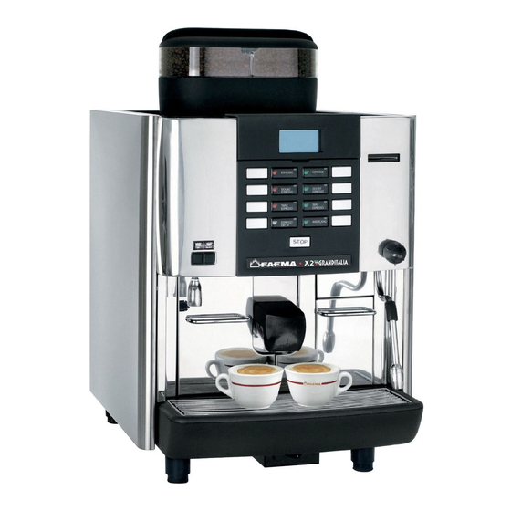
English English 1. Description of the machine X2 GRANDITALIA... -
Page 4: Description Of The Control Panel
English English 2. Description of the control panel X2 GRANDITALIA DESCRIPTION OF THE COMPONENTS Delivery spout Selection panel Graphical display Coffee hoppers 1 Coffee hoppers 2 Hot water button Steam dispensing knob (Autosteam selector*) Hot water outlet Steam pipe Tray... - Page 5 English English...
-
Page 6: Data Flow Chart - Technician Programming
English English 3. Data flow chart - Technician programming To ACCESS menu To EXIT menu press PRG press RES Insert the technician smart card KEY MENU CONFIGURATION TESTING Press Press Press SELECTION Type SPECIAL KEYS MANUAL COMMANDS Cappuccino flow PRESS. CALIBRATION Ser. -
Page 7: Programming
English English 4. Programming How to enter “Programming” menu : Insert the smart card. Access and modification of sub-menus : Use the “+” (30) and “- Besides the date and hour, the word TECHNICIAN will appear. “ (31) keys to position the cursor (black line) on the desired line, then press the PRG (29) key. - Page 8 English English 5.1 Key menu - Milk selection Press one of the milk dispensing keys (32). The related LED remains Milk selection parameters that can be changed are: on and does not blink. The display appears as follows: - Type (personalization key, i.e., 1 cappuccino, 2 coffees, 2 cappuccinos, milk, short washing, stop, disable);...
-
Page 9: Test Board
English English Key menu - Hot water selection Press the hot water dispensing key (12). The following message will The following hot water selection parameters can be modified: appear on the display: - Water dose (dispensing time in seconds.). KEY MENU Type Water dose 05.0... -
Page 10: Configuration Menu
English English 7. Configuration menu Buzzer - The machine buzzer can be enabled so that a beep is heard CONFIGURATION when the keys are pressed. SPECIAL KEYS ser. boiler press. 1,4 bar WASHING OPTIONS - See paragraph "Washing options" on the Group temp. -
Page 11: Autosteam
English English 8. Autosteam - Programming function Once you have selected TURBOSTEAM, use the “+” and “-“ keys to You may now program the automatic steam function, by setting a position the cursor on the T STOP STEAM line, and press the PRG key. “xxx°C”... -
Page 12: Washing Options
English English (Where is present) The ideal setting for milk frothing is set in the factory. If additional adjustments must be made, turn the flow adjustment valve (A) underneath the panel control of the machine: counterclockwise: more air > more frothy milk clockwise: less air >... - Page 13 English English 10. Test menu The ideal boiler pressure setting is made in the factory with a TESTING standard number. If further adjustments must be made, please follow MANUAL COMMANDS these instructions. PRESS. CALIBRATION The procedure must be performed when the machine is cold or with a boiler pressure of approximately 0 bar.
-
Page 14: Data Menu: Counters
English English 12. DATA menu: COUNTERS Once you have entered the programming menu, access the DATA COUNTERS MENU MENU, pressing the “i” (27) key. The following will be displayed: N° MSX N° MDX Hours DATA MENU COUNTERS MENU INFO WASH 1 ARCHIVE MALFUNCT. - Page 15 English English Version The sub-menu of the Version entry shows the memory display version When the PRG (29) key is pressed when the cursor is on each of the and, if present, also the remote control: two lines, besides showing the version, it also displays the data for the revision and memory date.
-
Page 16: Data Menu: Wash 1 Archive
English English 14. DATA menu: WASH 1 ARCHIVE The parameters for the WASH 1 log that can appear on the display DATA MENU are: COUNTERS MENU - Requests: number of wash cycles that have been requested INFO by the machine. WASH 1 ARCHIVE - Executed: number of wash cycles that were performed within the timeout time of 60'. -
Page 17: Customer Parameters Menu
English English 16. CUSTOMER PARAMETERS menu Use the “+” (30) and “-“ (31) keys to move the cursor (black line) To access "Customer parameters" press " " key (34); to the entry to be modified, then press the PRG (29) key. The message shown below will appear on the display: cursor will turn into an arrow è... - Page 18 English English 17. Manual control panel Move the cursor to the “manual commands” line with the “+” (30) and “-” (31) keys to access the manuals control panel. TECHNICAL PROG. KEY MENU CONFIGURATION MANUAL COMMANDS WEIGHTING A pressure of "PRG" key (29), visualizes on display the following panel: Panel 1 °...
- Page 19 English English Panel 2 ° ° → → R E S ± Press "+" (30) or "-" (31) to activate the components, if they have a direction, use "+" (30) and "-" (31) to alternate the activations (+Lh/-Rh or +Up/-Down, +Widen/-Narrow the grinders) and to switch to the next panel M3.
-
Page 20: Defects - Malfunctions
English English 18. Defects - Malfunctions MALFUN. DESCRIPTION POSSIBLE CAUSES SOLUTIONS CODE During operation, the overcurrent interrupt switch is triggered 3 times during the current threshold search phase. The error is recorded in the error log, but does not cau- se the machine to malfunction. - Page 21 English English 18. Defects - Malfunctions MALFUN. DESCRIPTION POSSIBLE CAUSES SOLUTIONS CODE Steam thermocouple • Disconnected Open the machine (Turbosteam) thermocouple - Check cabling Value is outside of acceptable range • Malfunctioning card - Replace the thermocouple - Replace the card KTY plugs (group) •...
- Page 22 English English 18. Defects - Malfunctions MALFUN. DESCRIPTION POSSIBLE CAUSES SOLUTIONS CODE Default data input Not working machine, with - Control the feeding presence in the electrical net display extinguished system - If there is power: 1 Open the machine 2 Check the feeding presence in the main electrical terminal CT and in the transformer TR - If there’s power:...
- Page 23 English English...
-
Page 24: Cpu Board Connectors
English English 19. CPU board connectors INDEX Page CPU Board Y12 Connector: group engine, unit resistance, solenoid valves Y4 Connector: Unit limit switches Y3 Connector: volumetric meter, grinders encoder, level Y5 Connector: grounds tray, decaffeinated Y11 Connector: triac boards command Y8 Connector: group temperature sensor Y14 Connector: coffee empty receiver Y6 Connector: boiler thermocouple... - Page 25 English English 1. CPU Board POT1: SW1: Y4: Unit limit Y13: feeding Y9: BUS 485 input input LCD Contrast Dip-Switches pin 1-5 10Vac (±10%) pin 7-8 Y5: ground tray Y1: Keyboard Y3: Encoder 24Vac (±10%) CLOCK Chip and decaff. Led Display and Level input input EVEN...
- Page 26 English English CPU Board = OK when: 1 2 3 4 5 6 7 8 9 0 1 2 3 4 5 6 7 8 9 0 1 2 3 4 5 6 7 8 9 0 1 2 1 2 3 4 5 6 7 8 9 0 1 2 3 4 5 6 7 8 9 0 1 2 3 4 1 2 3 4 5 6 7 8 9 0 1 2 3 4 5 6 7 8 9 0 1 2 3 4 5 6 7 8 9 0 1 2 1 2 3 4 5 6 7 8 9 0 1 2 3 4 5 6 7 8 9 0 1 2 3 4 1 2 3 4 5 6 7 8 9 0 1 2 3 4 5 6 7 8 9 0 1 2 3 4 5 6 7 8 9 0 1 2 1 2 3 4 5 6 7 8 9 0 1 2 3 4 5 6 7 8 9 0 1 2 3 4 V alim.
- Page 27 English English Connector Y12-21_E-R Y12-11_E-R Y12-1_D-R RED - MOT Y12-4_E-R Y12-19_E-R Y12-8_E-R Y12-10_E-R Y12-18_E-R Y12-17_E-R Y12-16_E-R Y12-24_E-R Y12-22_E-R Y12-20_E-R Y12-5_E-R Y12-6_E-R Y12-6_E-R Y12-7_E-R Y12-9_E-R Y12-2_D-NE BLACK - MOT Y12-3_E-R Y12-15_E-R Fuse 1 • Ets, El, Ear, Eac, Em, Eep, Evc, G, Eva * Solenoid valves pin: 4, 5, 6, 7, 8, 10, 15, 16, 17, 18, 19, 20, 21, pin:...
- Page 28 English English Connector • Solenoid valves pin: 4, 5, 6, 7, 8, 10, 15, 16, 17, 18, 19, 20, 21, 22, 24 • Mc, Compressor motor pin: 4, 9 • Group engine pin: 1,2 • Unit resistance pin: 3, 11 Fuse 2 Fuse 1 Solenoid valves: connectors Y19 - Y20...
- Page 29 English English Connector RED ISO3 Y4-4_E-R Y4-2_E-R GREEN ISO3 Y4-8_E-R RED ISO3 Y4-6_E-R GREEN ISO3 Y4-12_E-R RED ISO3 Y4-10_E-R GREEN ISO3 X05M X05L X05H X06M X06L X06H MIDDLE HIGH X06L X06M X06H X05L X05M X05H Y4-11_E-R WHITE ISO3 Y4-9_E-R BLACK ISO3 Y4-7_E-R WHITE ISO3 Y4-5_E-R...
- Page 30 English English Connector • Unit limit switches X05L pin: 1, 2, 3, 4 X05M pin: 5, 6, 7, 8 X05H pin: 9, 10, 11, 12 X05H X05M X05L X06L Unit limit switches: connectors X05/L, M, H - X06M X06/L, M, H X06H...
- Page 31 English English Connector LEVEL1 Y3-15 E-NE Y3-14 E-NE Y3-10 E-R Y3-12 E-NE EC Msx2 Y3-11 E-BL Y3-7 E-R Y3-9 E-NE EC Msx1 Y3-8 E-GR Y3-6 E-NE Y3-5 E-GI (+)1 Y3-4 E-R (-)2 • DV, Volumetric meter pin: 4, 5, 6 pin: 4 - 6 = 12V dc •...
- Page 32 English English Connector • Volumetric meter pin: 4, 5, 6 • Grinders Encoder Msx1 pin: 7, 8, 9 Mdx2 pin: 10, 11, 12 • Level pin: 14,15 Volumetric meter Grinders Encoder: connectors EC Msx 1 - EC Mdx 2 EC Msx 2 EC Msx 1 EC Msx 2 EC Msx 1...
- Page 33 English English Connector X015 X014 Y5-5_E-NE RED ISO3 DEKB DEKA Y5-8_E-NE GREEN ISO3 Y5-4_E-NE Y5-3_E-NE Y5-7_E-NE WHITE ISO3 Y5-6_E-NE BLACK ISO3 X015 X014 DEKB DEKA • Rc, Grounds tray pin: 3,4 • DC, Decaffeinated pin: 5, 6, 7, 8...
- Page 34 English English Connector • Grounds tray pin: 3,4 • Decaffeinated pin: 5, 6, 7, 8 Ground tray: connectors GTA - GTB Decaffeinated: connectors X014 - X015 - DEKA - DEKB X014/X015 DEKA DEKB DC pin: 11, 12, 13, 14...
- Page 35 English English Connector Y11-4_E-NE Y11-3_E-NE Y11-9_E-NE Y11-10_E-NE X03B Y11-7_E-NE Y11-6_E-NE Y11-5_E-NE Y11-1_E-NE Y11-2_E-NE • Triac boards command X03, Triac board: pin: 1, 2, 3, 4 X03B, Grinders triac board: pin: 5, 6, 7, 9, 10...
- Page 36 English English Connector • Triac boards command pin: 1, 2, 3, 4 X03B pin: 5, 6, 7, 9, 10 Grinders triac board: connectors X03B X03B X03B Triac board: connector X03 X014/X015...
- Page 37 English English Connector Y8-1E-NE KTYB KTYA Y8-2_E-BL KTYB KTYA • Group temperature sensor pin: 1, 2 KTYB Group temperature sensor: connectors KTYA - KTYB KTYA KTYA KTYB...
- Page 38 English English Connector X015 X014 Y14-5_E-NE Y14-3_E-BL Y14-6_E-R Y14-4_E-BL Y14-1_E-NE Y14-2_E-NE X015 X014 • Coffee empty receiver Coffee empty receiver: connectors X014 - X015 DC pin: 1÷8 X014/X015...
- Page 39 English English Connector CPU cod. 431.082.020 Yellow + Red - • Autosteam thermocouple , pin: 3, 4 CPU cod. 431.082.010 Yellow + Red - • Boiler thermocouple , pin: 3, 4...
- Page 40 English English Connector Y7-1 NE CPU cod. Y7-2 BL 431.082.020 Y7-3 R • Pressure sensor , pin: 1, 2, 3 CPU cod. 431.082.010 Yellow + Red - • Autosteam thermocouple , pin: 3, 4...
- Page 41 English English...
-
Page 42: Index Of The Movimentation Group Phases
English English 20. Index of the movimentation group phases INDEX Page Standby position Grinding phase Starting moving up phase Intermediate moving up phase 1 Intermediate moving up phase 2 Ending moving up phase - Backing Dispensing phase Ending dispensing phase - Drying Starting moving down phase Intermediate moving down phase Ending moving down phase -1-... - Page 43 English English 1. Standby position 2. Grinding phase FC2 = 0 FC2 = 0 FC1 = 1 FC1 = 1 FC3 = 0 FC3 = 0 3. Starting moving up phase 4. Intermediate moving up phase 1 FC2 = 0 FC2 = 0 FC1 = 0 FC3 = 0...
- Page 44 English English 5. Intermediate moving up phase 2 6. Ending moving up phase - Backing FC2 = 0 FC2 = 1 7. Dispensing phase 8. Ending dispensing phase - Drying FC2 = 0 FC2 = 0...
- Page 45 English English 9. Starting moving down phase 10. Intermediate moving down phase FC2 = 0 FC2 = 1 FC1 = 0 FC1 = 1 FC3 = 0 FC3 = 0 11. Ending moving down phase -1- 12. Ending moving down phase -2- FC3 = 0 FC3 = 0...
- Page 46 English English 13. Coffee ground expulsion -1- 14. Coffee ground expulsion -2- FC3 = 0 FC3 = 1 15. Returning standby position 16. Standby position FC2 = 0 FC2 = 0 FC1 = 1 FC1 = 0 FC3 = 0 FC3 = 0...
- Page 47 English English 17. Weighting Standby Weighting phase FC3 = 1...
- Page 48 Smontaggio - Disassembly - Demontage Abmontierung - Desmontaje - Desmontagem Pag. - Page Page - Seite Pag. - Pag. Apertura pannello comandi - Opening the command panel. Ouverture du tableau des commandes - Öffnung der Schalttafel Abertura panel mandos - Abertura painel de comandos Rimozione tramoggia - Removal of the coffee beans receptacle Soulèvement de la trémie - Abnahme des Trichters Extracción tolva- Remoção da tremonha...
- Page 49 Prima di effettuare operazioni di apertura o smontaggio di parti della carrozzeria della macchina, togliere l'alimentazione elettrica agendo sull'interruttore principale dell'impianto elettrico del cliente. Switch off the electricity via the mains switch before opening or dismantling the chassis of the machine. Avant d’effectuer les opérations d’ouverture ou de démontage des parties représentant la carrosserie de la machine, s’assurer de bien avoir déconnecté...
- Page 50 Rimozione tramoggia - Removal of the Coffee Beans Receptacle Soulèvement de la trémie - Abnahme des Trichters Extracción tolva - Remoção da tremonha Svitare la vite (V) e ruotare in senso orario la maniglia (M). Sollevare e rimuovere la tramoggia (6). Unscrew the screw (V) and turn the handle (M) clockwise.
- Page 51 Pannello posteriore - Back Panel Panneau postérieur - Abnahme des hinteren Paneels Panel posterior - Painel traseiro Svitare le due viti (P) di fissaggio e rimuovere il pannello. Loosen the screws (P) and remove the panel. Dévisser les vis (P) de fixage et enlever le panneau. Lösen Sie die Schrauben (P) zur Befestigung, und nehmen Sie das hintere Paneel ab.
- Page 52 Scatola elettrica - Junction Box Boite électrique - Elektrokasten Caja eléctrica - Caixa eléctrica Togliere la bacinella appoggiatazze (16). Die Wanne zur Tassenabstellung (16) abnehmen. Svitare le due viti (A) anteriori e le due viti (P) posteriori di Die beiden vorderen Schrauben (A) und die beiden hinteren fissaggio e rimuovere la scatola elettrica (S).
- Page 54 Regolazioni - Setting - Reglages Einstellung - Regulaciónes - Regulações Pag. - Page Page - Seite Pag. - Pag. Pompa volumetrica - Volumetric pump Pompe volumetrique - Volumetrische Pumpe Bomba volumetrica - Bomba volumetrica Regolazione aria cappuccino - Cappuccino air setting Réglage de l’air du cappuccino - Regelung der Luft zur Cappuccino-Zubereitung - Regulación aire capuchino Regulação ar garoto (cappuccino)
- Page 55 Pompa volumetrica - Volumetric pump Pompe volumetrique - Volumetrische Pumpe Bomba volumetrica - Bomba volumetrica BY- PASS (A) - Vite di regolazione pressione pompa. Tarare a 9÷10 bar a mandata chiusa. BY-PASS (A) - Screw for adjusting the pump pressure. Calibrate to 9 ÷...
- Page 56 Regolazione granulometria - Granulometry Setting Réglage granulométrie - Regler Mahlfeinheit Regulación granulometría - Regulação da granulometria Svitare le viti (C) e (D) e rimuovere il pannello superiore. Svitare le viti (E) e rimuovere le staffe (S). Ruotare in senso orario la ghiera graduata per stringere la macinatura (9 - 8 - ...);...
- Page 57 Regolazione contrasto display - Display contrast setting Reglage du contraste du display - Einstellung des kontrasts der Display Regulación del contraste del display - Reglage do contraste do display REGOLAZIONE CONTRASTO DISPLAY EINSTELLUNG DES KONTRASTS DER DISPLAY Agire sul trimmer (A) posto sulla scheda elettronica affinchè Stellen Sie den auf der Elektronikkarte installierten Reger (A) sul display si leggano i messaggi in modo chiaro.
- Page 58 Dip-Switch CPU - CPU Dip-Switch Dip-Switch CPU - Dip-Switch CPU Dip-Switch-Schalter CPU - Dip-Switch CPU Attenzione! Il cambiamento di posizione dei Dip-Switch deve essere effettuato RIGOROSAMENTE a macchina SPENTA. Nelle condizioni standard i Dip-Switch sono posizionati su OFF. Agendo sui Dip-Switch (O) si attivano le seguenti funzioni: - DIP 1 = OFF - ON inserimento dati standard (*) - DIP 2 = OFF - DIP 3 = OFF - ON simulazione chiave tecnico...
- Page 59 Termostato di sicurezza - Safety thermostat Thermostat de sureté Sicherheitsthermostat Thermostato de seguridad - Thermostato de segurança In caso di intervento del termostato, riarmare In case of thermostat intervention, switch on again En cas d'intervention du thermostat, brancher de nouveau Falls der Thermostat ausgelöst wird, ihn wiederienschalten En caso de intervención del thermostato, reencender de nuevo En caso de incarvenção do termostato, reacender de novo.
- Page 60 Cambio della tensione di alimentazione del trasformatore - Changing the voltage of the transformer Changement de la tension d'alimentation du transformateur - Änderung der transformator-speisespannung Cambio de tension de alimentacion del transformador - Madunça de tensão de alimentação do transformador Per accedere al cambia tensione di alimentazione, occore svitare le due viti (T) poste sul retro della macchina.
Need help?
Do you have a question about the X2 Granditalia and is the answer not in the manual?
Questions and answers