Table of Contents
Advertisement
Quick Links
Installation Instructions
Original Instructions
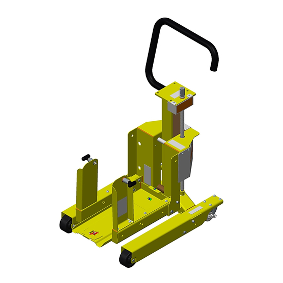
PowerFlex 750-Series Service Cart Frames 8...10 Conversion Kit
Bulletin Numbers 20G and 21G
Topic
Service Cart Frames 8...10 Conversion Kit Components
This publication provides basic information to disassemble the 20-750-MCART1 service cart and attach the 20-750-MPLT755T frame 8...10
conversion kit for use with PowerFlex 750-Series frame size 8...10 modules, bulletin numbers 20G and 21G.
The PowerFlex® 750-Series service cart was initially designed to handle and transport PowerFlex 755T modules that are used with PowerFlex 750-
Series products with TotalFORCE™ control. The frames 8...10 conversion kit allows the PowerFlex 750-Series service cart to be converted to a
service cart capable of removing the power modules in the PowerFlex 750-Series frame 8...10 product size.
To use the PowerFlex 750-Series frames 8...10 module conversion kit catalog number 20-750-MPLT755T, you must first follow the instructions to
unpack and stage the PowerFlex 750-Series service cart 20-750-MCART1. Some disassembly of the PowerFlex 750-Series service cart will be
required.
Personal Safety
ATTENTION: The PowerFlex 750-Series service cart (20-750-MCART1) weighs approximately 60 kg (133 lb) and requires two persons to lift.
The PowerFlex 750-Series service cart frames 8...10 conversion kit (20-750-MPLT755T) weighs approximately 32 kg (70 lb) and requires two persons to lift.
ATTENTION: Personal protective equipment is required to perform this installation. At minimum, goggles, steel toe shoes, and gloves should be used.
Page
Topic
3
Install the Frames 8...10 Conversion Kit
5
2
6
7
Page
8
9
10
11
12
Advertisement
Table of Contents

Related Manuals for Rockwell Automation Allen-Bradley PowerFlex 750-21G


Summary of Contents for Rockwell Automation Allen-Bradley PowerFlex 750-21G
-
Page 1: Table Of Contents
Installation Instructions Original Instructions PowerFlex 750-Series Service Cart Frames 8…10 Conversion Kit Bulletin Numbers 20G and 21G Topic Page Topic Page Before You Being Install the Frames 8…10 Conversion Kit Setup the Service Cart Adjust the Service Cart Service Cart Components Service Cart Requirements and Safety for Power Module Removal Disassemble the Service Cart and Stage for Conversion Move the Power Module... -
Page 2: Service Cart Components
(2) This item must be removed to use the PowerFlex 750-Series frames 8…10 module conversion kit. See Setup the Service Cart on page 5 for additional instructions. ATTENTION: The PowerFlex 750-Series service cart (20-750-MCART1) weighs approximately 60 kg (133 lb) and requires two persons to lift. Rockwell Automation Publication 750-IN017B-EN-P - June 2018... -
Page 3: Before You Being
Electric drill with torque rating 11.3 N•m (100 lb•in), min Pliers T45 hexalobular bit Aisle Clearance The minimum aisle clearance that is required to maneuver and position the service cart is 914 mm (36 in.). Top View 914 mm (36 in.) Rockwell Automation Publication 750-IN017B-EN-P - June 2018... - Page 4 Do not push or pull above the points that are indicated on the power module. Renewal Part Availability Description Cat. No. PowerFlex 750-Series frame 8…10 conversion plate safety SK-R1-CARTCLIP clips Rockwell Automation Publication 750-IN017B-EN-P - June 2018...
-
Page 5: Setup The Service Cart
To align the holes, pull the wheel mount up. 3. Lower the undercarriage wheel mount to its horizontal position. 4. Insert the wheel mount clevis pin through the forward holes of the undercarriage wheel mount and secure with the cotter pins. Rockwell Automation Publication 750-IN017B-EN-P - June 2018... -
Page 6: Disassemble The Service Cart And Stage For Conversion
2. Use the T40 hex bit to remove the four M8 bolts that connect the left and right vertical supports to the carriage assembly. 3. Use the T40 hex bit to remove the four M8 bolts that connect the bridge floor to the carriage assembly. Rockwell Automation Publication 750-IN017B-EN-P - June 2018... -
Page 7: Service Cart Frames 8
(1) This item comes pre-attached to the frames 8…10 bridge plate. ATTENTION: The PowerFlex 750-Series service cart frames 8…10 conversion kit weighs approximately 32 kg (70 lb) and requires two persons to lift. Rockwell Automation Publication 750-IN017B-EN-P - June 2018... -
Page 8: Install The Frames 8
The plate being in position A, results in the four anchor pins being inserted into the four position A locations. M10 nut T30 / 15 mm 19.8 N•m (175 lb•in) T25 / 15 mm 10.2 N•m (90 lb•in) Rockwell Automation Publication 750-IN017B-EN-P - June 2018... -
Page 9: Adjust The Service Cart
0 mm (0 in.) is the lowest possible cart position. A = 0 mm B = 57 mm C = 130 mm (2.2 in.) (5.1 in.) 0…137 mm 0…130 mm (0…5.4 in.) (0…5.1 in.) Rockwell Automation Publication 750-IN017B-EN-P - June 2018... -
Page 10: Service Cart Requirements And Safety For Power Module Removal
• Pinch Point B: When lowering the service cart bridge, keep this area clear. The bridge will make direct contact with the carriage assembly when the service cart is lowered. Rockwell Automation Publication 750-IN017B-EN-P - June 2018... -
Page 11: Move The Power Module
ATTENTION: To guard against death, serious personal injury, or equipment damage, do not subject the power module to high rates of acceleration or deceleration while transporting. Power modules have a high center of gravity. Do not push or pull above the points that are indicated on the power module. Rockwell Automation Publication 750-IN017B-EN-P - June 2018... -
Page 12: Store The Service Cart
Service Cart Maintenance Inspect the service accessories for damage or excessive wear before each use. Lubricate the jackscrew and thrust bearing on the service cart every 2 years. Renolit ST-80 lithium grease is recommended. Rockwell Automation Publication 750-IN017B-EN-P - June 2018... - Page 13 PowerFlex 750-Series Products with TotalFORCE Control Technical Data, 750-TD100 Go to: http://www.rockwellautomation.com/global/literature-library/overview.page to view or download publications. To order paper copies of technical documentation, contact your local Allen-Bradley distributor or Rockwell Automation sales representative. Rockwell Automation Publication 750-IN017B-EN-P - June 2018...
- Page 14 Rockwell Automation maintains current product environmental information on its website at http://www.rockwellautomation.com/rockwellautomation/about-us/sustainability-ethics/product-environmental-compliance.page. Allen-Bradley, PowerFlex, Rockwell Automation, Rockwell Software, and TotalFORCE are trademarks of Rockwell Automation, Inc. Trademarks not belonging to Rockwell Automation are property of their respective companies. Rockwell Otomasyon Ticaret A.Ş., Kar Plaza İş Merkezi E Blok Kat:6 34752 İçerenköy, İstanbul, Tel: +90 (216) 5698400...
Need help?
Do you have a question about the Allen-Bradley PowerFlex 750-21G and is the answer not in the manual?
Questions and answers