Table of Contents
Advertisement
Welcome to Follett
Follett equipment enjoys a well-deserved reputation for excellent performance, long-term reliability and outstanding
after-the-sale support. To ensure that this equipment delivers that same degree of service, review this guide
carefully before you begin your installation.
Should you need technical help, please call our Technical Service group at (877) 612-5086 or (610) 252-7301.
Please have your model number, serial number and complete and detailed explanation of the problem when
contacting Technical Service.
Getting Started
After uncrating and removing all packing material, inspect the equipment for concealed shipping damage. All freight
is to be inspected upon delivery. If visible signs of damage exist, please refuse delivery or sign your delivery receipt
"damaged." Follett Customer Service must be notified within 48 hours. Wherever possible, please include detailed
photos of the damage with the original packaging so that we may start the freight claim process.
801 Church Lane • Easton, PA 18040, USA
Toll free (877) 612-5086 • +1 (610) 252-7301
www.follettice.com
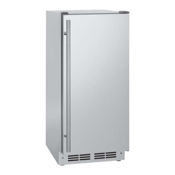
Undercounter Ice Machine Bin
Operation and Service Manual
Tempo™
Installation and Service Videos:
www.follettice.com/servicevideolibrary
01234673R00
Advertisement
Table of Contents
Troubleshooting

Subscribe to Our Youtube Channel
Related Manuals for Follett Tempo UCD100A30-NF


Summary of Contents for Follett Tempo UCD100A30-NF
- Page 1 If visible signs of damage exist, please refuse delivery or sign your delivery receipt "damaged." Follett Customer Service must be notified within 48 hours. Wherever possible, please include detailed photos of the damage with the original packaging so that we may start the freight claim process.
- Page 2 § This appliance must not be cleaned by a water jet. § User maintence should not be done by children. § Follett recommends a Follett water filter system be installed in the ice machine inlet water line (standard capacity #00130229, high capacity #00978957, carbonless high capacity #01050442).
-
Page 3: Before You Begin
If needed, the serial number of your dispenser can be found by opening the door and locating the serial number label at the top right inside of the machine. Note: For indoor use only. Designed for commercial use. Follett is not able to provide in-house services for residential installations. -
Page 4: Specifications
(81.3 cm to 83.8 cm) * Leveling legs, adjustable up to 0.25" (6.4 mm). Ambient Information CAUTION! This unit is for indoor use only. Designed for commercial use. Follett is not able to provide in-house services for residential installations. Maximum* Minimum*... - Page 5 Water WARNING! Connect to potable water supply only. § Water Mineral Content: – TDS: greater than 5 ppm (mg/l) but less than 400 ppm (mg/l) – Hardness: Less than 200 mg/l (12 gpg) § Not recommended for use with softened water §...
- Page 6 Tempo Detailed Drawing air exhaust air inlet 3.125" (8.0 cm) Water Line 7.5" (19.1 cm) Drain 7.5" (19.1 cm) 4" 4" (10.2 cm) (10.2 cm) Power Cord 2" 6' (1.83 m) (5.1 cm) W1 Width 14.96" (38.0 cm) C1 115 V/60/1 electrical 2 amps.
-
Page 7: Site Preparation
Site Preparation Your product has been designed for either freestanding or built-in installation. When built-in, your unit does not require additional air space for top, sides, or rear. However, the front grille must NOT be obstructed, and clearance is required for an electrical connection in the rear. Unit can NOT be installed behind a closed cabinet door. - Page 8 NOTE: To meet sanitary requirements in some areas, installer must Fig. 1 leave sufficient length (waterline, drain line, power cord) to permit the equipment to be moved for cleaning.Turn off water supply and disconnect electrical supply to product prior to attempting installation.
- Page 9 Hinge Cover Fig. 4 Hinge cover included with the literature bag is optional. 1. Press hinge cover squarely over hinge. Hinge Cover To Reverse the Door (if required) Fig. 5 Remove top hinge and door: 1. Hold door to keep it from falling. 2.
-
Page 10: Door Alignment And Adjustment
Install Bottom Hinge Fig. 8 1. Install two or three screws, depending on model. Replace nuts if used. Prepare Door for Reinstallation 1. Remove gasket. 2. Rotate gasket 180° and press firmly into the gasket channel, starting at the corners. 3. - Page 11 Leveling Information Fig. 10 Installation Tip Note: If the room floor is higher than the floor in the cutout opening, adjust the rear legs to achieve a total unit rear height of 1/10" (2.54 mm) less than the opening’s rear height. Shorten the unit height in the front by adjusting the front legs.
-
Page 12: Control Operation
Initial startup requires no adjustments. See CONTROL OPERATION section for more details. 1. Follett recommends discarding the ice produced during the first two to three hours of operation to avoid possible dirt or scale that may dislodge from the water line. - Page 13 Cleaning This ice machine has an automatic clean alert function. The control will indicate in the display, approximately every six months with normal use, reminding you to clean your unit. When is displayed, ice production will continue. Depending on water conditions, more frequent cleaning may be necessary.
- Page 14 Press and release will appear in the display. 9. Mix 4 ounces of SafeCLEAN Plus™ with 2 quarts of hot potable water (100 F minimum). 10. Wait until appears in the display. 11. Using the funnel and cleaning tube, slowly pour 3/4 of the cleaning solution into the dispenser tube. Air and some water will exit the vent tube.
-
Page 15: Troubleshooting
If display shows error “dr” , check to make sure door is sealing correctly. Make sure to close door completely. If sealing the door does not clear the error, contact Follett. Unit Develops Condensation on External Surfaces The unit is exposed to excessive humidity. - Page 16 Disassembly - Access to Evaporator Fig. 14 1. Disconnect power from the dispenser. 2. Turn off water supply to dispenser. 3. Empty all ice from the unit and discard. 4. Tilt the unit and remove the six screws from the bottom of the chassis.
- Page 17 6. Remove 2 thumbscrews (Fig. 16.1) and 4 Phillips-head screws Fig. 16 (Fig. 16.2) holding front panel. Remove front panel. Remove the two spade connections from the door switch (Fig. 16.3) at the front of the unit. 8. Remove the two screws securing the control box at the front of the Fig.
- Page 18 10. Remove the 6 screws holding the lower back panel. Remove panel. Fig. 18 11. Remove the 8 screws holding the upper back panel. Remove panel. 12. Using a 1/4" socket with an extension or a long-handled flat head screwdriver, remove the two screws located inside the back of the unit.
- Page 19 13. Disconnect the vent tube. Fig. 20 14. Loosen the hose clamp and disconnect the ice transport tube from Fig. 21 the nozzle. 15. Disconnect the filter line. Fig. 22 Tempo Undercounter Ice Machine Bin...
- Page 20 16. Disconnect the two electrical connections. Fig. 23 17. From front of unit, reach in and loosen the hose clamp at the top of Fig. 24 the elbow and then disconnect the drain line. 18. Place the elctrical box back inside the unit. 19.
- Page 21 Evaporator Disassembly Fig. 26 1. Disconnect power from the dispenser. 2. Turn off water supply to dispenser. 3. Remove the screw securing the start capacitor. 4. Unplug the gear motor (three connectors) (Fig. 26). 5. Remove ground screw connection. ? 6. Remove gear motor: Fig.
- Page 22 9. Remove main housing: Fig. 29 § Disconnect vent line from T fitting (Fig. 29.1). 10. Remove three M6x25 socket head allen screws and vent tube clip Fig. 30 (Fig. 30.1). 11. Remove main housing (Fig. 30.2). 12. Remove and discard mating ring and seal (Fig. 31.1). Fig.
- Page 23 Evaporator Assembly Fig. 32 1. Remove and inspect main housing O-ring seal. Replace if damaged in any way. 2. Clean O-ring groove. Lubricate O-ring with Petrol-gel and reinstall. 3. Use cardboard disc to press new mating ring into main housing (Fig.
- Page 24 8. Install transport tube (Fig. 35.1). Fig. 35 9. Tighten hose clamp (Fig. 35.2). 10. Install gear motor: Fig. 36 § Install main housing insulation (Fig. 36.1). § Slide gear motor onto auger shaft (Fig. 36.2). § Install two M6x90 allen screws (Fig. 36.3). 11.
- Page 25 13. Install spacer, ensure that key is captured in slot (Fig. 38.1) Fig. 38 14. Insert screwdriver into groove of auger shaft and pry shaft Fig. 39 outwards (Fig. 39.1). 15. Insert retainer into groove (Fig. 39.2), ensure that retainer is aligned with hole in spacer. 16.
- Page 26 17. Plug in gear motor (Fig. 41). § BLUE to BLUE § BLACK to BLACK § WHITE to WHITE § Connect ground wire with ground screw. Fig. 41 Tempo Undercounter Ice Machine Bin...
- Page 27 Water Feed Schematic Water Solenoid Valve Filter (optional) (optional) Water Solenoid Valve Vent System Schematic Vent Tube Reservoir Tempo Undercounter Ice Machine Bin...
-
Page 28: Electrical Wiring Diagram
Electrical Wiring Diagram Tempo Undercounter Ice Machine Bin... - Page 29 Refrigeration Schematic CONDENSER FILTER-DRIER CAP TUBE COMPRESSOR EVAPORATOR LOW PRESSURE LIQUID HIGH PRESSURE VAPOR HIGH PRESSURE LIQUID LOW PRESSURE VAPOR Tempo Undercounter Ice Machine Bin...
- Page 30 Refrigeration System Diagnostic Guide System Section Suction Line Compressor Condenser Capillary Evaporator Wattage Condition Pressure Discharge Tube Normal Normal Slightly Very hot Very hot Warm Cold Normal below room temperature Overcharge Higher than Very cold may Slightly warm Hot to warm Cool Cold Higher than...
-
Page 31: Compressor Specifications
Compressor Specifications DANGER! Electrocution can cause death or serious injury. § Burns from hot or cold surfaces can cause serious injury. Take precautions when servicing this unit. § Disconnect the power source. § Do not stand in standing water when working around electrical appliances. §... -
Page 32: Troubleshooting - Extended
Troubleshooting - Extended Specific Errors and Issues The advanced diagnostic capabilities of the electronic controls utilized on the 1, 3, and 5 Class units allow for easy and thorough troubleshooting. Navigation of the control is the key and is explained in the CONTROL OPERATION section of the manual, along with control button layout, control function descriptions, a service mode menu and service menu selection explanations. -
Page 33: Power Fault
Power Fault If the unit does not (or seems to not) power on, follow the flow chart below to help diagnose the issue. Before beginning it is important to first verify the unit is not simply set to sabbath mode Check Voltage Alert Customer No Voltage... - Page 34 Concern Potential Causes Action No Display or Interior Unit may be in Sabbath mode • Tap to turn off Sabbath mode, test the door Lights switch circuit. • Unplug unit, wait 5 seconds, plug back in. If main board does not beep, check for 120V at black and white cables on power cord.
-
Page 35: Error Codes
Plunger Switch Fig. 42 A plunger switch is used to monitor door state. When the door is closed it comes into contact with the plunger which closes a circuit which turns the light and display off. When the door is open the plunger moves outward and opens the circuit. - Page 36 Control Operation-Service UI Button Layout 1. Hidden Button § Access Service Menu § No LED directly above. All LEDs turn on with button 2. Up Button § Increases temperature § Navigates through service menu 3. Down Button § Decreases temperature §...
-
Page 37: Silent Mode
Control Function Guide Function Command Display/options ON/OFF Unit will immediately turn ON or OFF Press and release Sabbath Mode See Sabbath Mode section Display will show 3H Silent Mode (ice production Hold suspended for 3 hours) Clean Mode See Cleaning section Silent Mode In some cases it may be requested for the unit to be shut down temporarily - during meetings for example. - Page 38 Parts Tempo Undercounter Ice Machine Bin...
- Page 39 Exterior Reference Description Part # Panel, access front 01305846 Panel, rear 01305853 Compressor 01305861 Condenser 01305879 Condenser, fan blade 01305887 Condenser, fan motor 01305895 Cover, with hook 01305903 Display assembly 01305911 Door assembly 01306133 Door assembly ADA 01305929 Drier 01305937 Valve, purge 01305945 Module, float, evaporator...
-
Page 40: Evaporator Assembly
Evaporator Assembly Tempo Undercounter Ice Machine Bin... - Page 41 Evaporator Assembly Reference # Description Part # Gearmotor Assy 00957811 Main Housing with Front Seal and Screws 00957829 Screws, Main Housing 00957837 Auger with front seal 00957845 Ice Compression Nozzle Assy 00957852 Front Seal and O-Ring 00957860 Evaporator Assembly with Insulation 01157353 Housing, Bushing with Insulation 00957886...
- Page 42 Tempo Undercounter Ice Machine Bin...
- Page 43 Tempo Undercounter Ice Machine Bin...
- Page 44 Please visit www.follettice.com/support to complete the Warranty Registration form. Should you have any questions, please contact Follett's technical support group at (877) 612-5086 or (610) 252-7301 and we will be happy to assist you.
Need help?
Do you have a question about the Tempo UCD100A30-NF and is the answer not in the manual?
Questions and answers