
Subscribe to Our Youtube Channel
Related Manuals for Roland Digital Snake S-2416


Summary of Contents for Roland Digital Snake S-2416
- Page 1 Before using the S-2416, ensure that its system program is at the most recent version. For information on available upgrades for the system program, see the Roland website (http://proav.roland.com).
- Page 2 The wire which is coloured BROWN must be connected to the terminal which is marked with the letter L or coloured RED. Copyright © 2014 ROLAND CORPORATION All rights reserved. No part of this publication may be reproduced in any form without the written permission of ROLAND CORPORATION.
-
Page 3: Using The Unit Safely
Roland Service Center, or an authorized Use only the supplied power cord the plug from the outlet Roland distributor, as listed on the “Information” when: • The power cord has been damaged; or Use only the attached power cord. Also,... - Page 4 USING THE UNIT SAFELY CAUTION CAUTION Place in a well ventilated location Handle the ground terminal carefully If you remove the screw from the ground The unit should be located so that its location or position does not interfere with terminal, be sure to replace it;...
-
Page 5: Important Notes
• Roland, REAC, and V-Mixer are either registered may cause this unit to malfunction or may produce is physically damaged, restoration of the stored trademarks or trademarks of Roland Corporation in audible noise. -
Page 6: Table Of Contents
Contents USING THE UNIT SAFELY . . . . . . . . . . . . . . . . . . . . . . . . . . . . . . . . . . . . . . . . . . 3 IMPORTANT NOTES . -
Page 7: Before Installing
Before Installing Changing Where the Rack-Mount Angles Are Attached • You can shift the location where the rack-mount angles are installed by 16 millimeters. • Attaching the rack-mount angles at the back lets you change the orientation in which the unit is mounted on a rack. NOTE Before carrying out this operation, detach all connections. -
Page 8: Panel Descriptions
Panel Descriptions Front Panel Name Explanation Various input devices are connected to these. The inputs include a variable-gain preamp that can accept signals from -65 through +10 dBu (nominal, maximum input: +28 dBu). The status of the connectors is displayed on 3 indicators. CLIP Lights in red when the input signal exceeds 0 dB (digital full scale). -
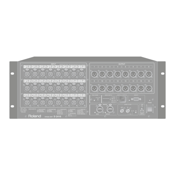
Page 9: Rear Panel
Panel Descriptions Name Explanation This is a female 9-pin D-sub connector. REMOTE connector It is used to connect a dedicated remote controller for digital snake devices (the S-4000R) or a computer installed with dedicated remote control software (S-4000RCS). The REMOTE indicator lights in orange when an S-2416 is communicating with S-4000R or computer via the REMOTE indicator RS-232C connection. -
Page 10: [Mode] Switches
When the unit is grounded, a slight hum may occur, depending on the particulars of your installation. If you are unsure of the connection method, contact the nearest Roland Service Center, or an authorized Roland distributor, as listed on the “Information” sheet. -
Page 11: Preparations For Power-Up
Preparations for Power-Up Connecting the Power Cord Turning the Power On and Off Connect the included power cord to the AC IN connector on rear * Before turning the unit on/off, always be sure to turn the volume panel. Be sure to use the included power cord for connecting the down. -
Page 12: Connecting Reac Devices
Cables for REAC Connections With Digital Snake and V-Mixing Systems, digital transmission of audio signals is performed by means of REAC (Roland Ethernet Audio Communication). Compared to analog transmission, this system is extremely resistant to external noise, but in very rare instances, noise can occur. -
Page 13: When Using Aes/Ebu Input
Connecting REAC Devices When Using AES/EBU INPUT AES/EBU S-2416: Slave V-Mixer: Master Mixer, etc. Word-clock generator S-2416 settings NOTE Change the setting of the [REAC MODE] switch and [MODE] switch while the S-2416 is powered down. [REAC MODE] switch Setting S (Slave) [MODE] switch Setting... -
Page 14: Connection
Connecting REAC Devices When Also Using AES/EBU INPUT with a Cascade Connection This gives an overview of the settings when connecting the V-Mixer with a cascade connection to an S-0816 unit. AES/EBU Mixer, etc. S-2416: Slave S-0816: Slave V-Mixer: Master Word-clock generator AES/EBU INPUT is the audio signals of inputs 25 through 32 on the S-2416. -
Page 15: When Using Duplex Reac Lines
Connecting REAC Devices When Using Duplex REAC Lines If the REAC MAIN signal is interrupted, communication automatically switches to REAC BACKUP. S-2416: Slave V-Mixer: Master S-2416 settings NOTE Change the setting of the [REAC MODE] switch and [MODE] switch while the S-2416 is powered down. [REAC MODE] switch Setting S (Slave) -
Page 16: When Connecting S-2416 Units To One Another
Connecting REAC Devices When Connecting S-2416 Units to One Another S-2416: Slave S-2416: Master NOTE Change the setting of the [REAC MODE] switch and [MODE] switch while the S-2416 is powered down. Slave-unit settings Master-unit settings [REAC MODE] switch Setting [REAC MODE] switch Setting S (Slave) -
Page 17: Connecting Devices
Connecting Devices * To prevent malfunction and equipment failure, always turn down the volume, and turn off all the units before making any connections. * This instrument is equipped with balanced (XLR) type jacks. Wiring diagrams for these jacks are shown on “INPUT/OUTPUT Connector” of “Connector Information”(p. -
Page 18: Connecting Digital Devices
Connecting Devices Connecting Digital Devices When connecting digital equipment, use a commercially available breakout cable and make the connection to the AES/EBU connector. * The AES/EBU connector is a 25-pin D-sub female connector wired as shown in “AES/EBU connector” in “Connector Information”(p. 25). Check the wiring of cables and equipment before connecting them. -
Page 19: Making Settings For The Input Channels
Making Settings for the Input Channels Making Settings Using an S-4000R Adjusting the Preamp Gain You can adjust the preamp gain on the S-2416 before sending the The S-4000R is a dedicated remote controller for digital snake signal to a mixer. devices. -
Page 20: Switching The Gain Range (Pad)
Making Settings for the Input Channels Switching the Gain Range (Pad) Supplying Phantom Power You can switch the pad on and off to change the variable range of You can supply phantom power from the S-2416 when a condenser the preamp gain for individual channels. microphone or other device requiring +48 V of power is connected. -
Page 21: Manipulating Two Channels As A Pair (Stereo Link)
Making Settings for the Input Channels Switching Off Stereo Link Manipulating Two Channels As a Pair (Stereo Link) NOTE Switching off Stereo Link does not make the values and other Using the Stereo Link feature lets you simultaneously manipulate settings go back to what they were before Stereo Link was two adjacent channels, one odd-numbered and one even (1 and 2, switched on. -
Page 22: Making Settings Using S-4000Rcs
You can make various settings for the input channel at the for digital snake devices to make the various settings for the input operation screen on the Roland V-Mixer. channels. Connect the V-Mixer to the S-2416, then make various settings at the CHANNEL DISPLAY screen. -
Page 23: Appendix
Replace with a new power cord. The power cord is damaged. – Consult with your retailer, the nearest Roland Service Center, or an authorized Roland distributor, as listed on the “Information” sheet. REAC has the following three operation modes, and the mode setting for each connected REAC device must be made correctly. -
Page 24: Main Specifications
Appendix Main Specifications Roland S-2416: STAGE UNIT Number of Channels 32 in 24 out Sample Rate: 96.0 kHz, 48 kHz, 44.1 kHz AD Conversion Signal Processing: 24 bits Sample Rate: 96.0 kHz, 48 kHz, 44.1 kHz DA Conversion Signal Processing: 24 bits -2 dB / +0 dB (@ +4 dBu, 20 Hz to 40 kHz, Sample Rate: 96 kHz, typ.) -
Page 25: Connector Information
Appendix Connector Information REAC connector Cat5e crossover wiring Cat5e straight wiring REMOTE connector * Cable length should be 15 meters or shorter. Pin No. Signal Pins Included RS-232C cable TxD (Data Out) RxD (Data In) Short to pin 8 Short to pin 7 INPUT/OUTPUT connector XLR balanced XLR unbalanced... -
Page 26: Dimensions
Appendix Dimensions UNIT: mm... - Page 27 Compliance Information Statement Model Name : S-2416 Type of Equipment : Audio I/O unit Responsible Party : Roland Corporation U.S. Address : 5100 S. Eastern Avenue Los Angeles, CA 90040-2938 (323) 890-3700 Telephone : For the USA FEDERAL COMMUNICATIONS COMMISSION...
- Page 28 For EU Countries For China...
Need help?
Do you have a question about the Digital Snake S-2416 and is the answer not in the manual?
Questions and answers