Table of Contents
Advertisement
Advertisement
Table of Contents

Subscribe to Our Youtube Channel
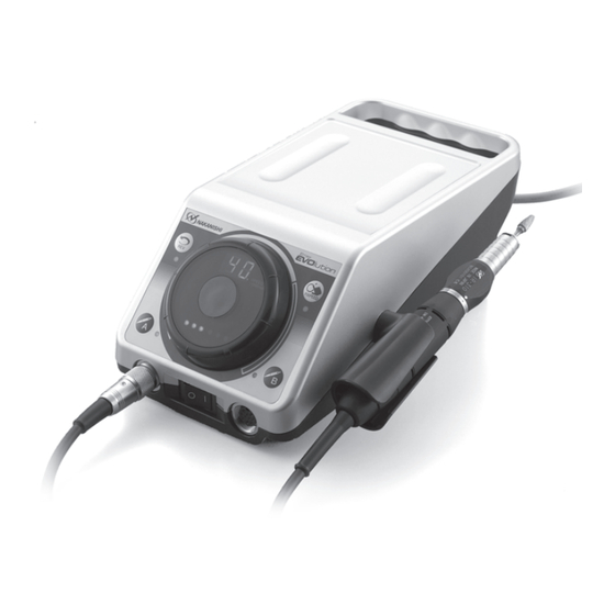
Summary of Contents for Nakanishi Emax Evoluion
- Page 1 OM-K0572E 004 2019.01.18 005Ⓐ...
-
Page 2: Table Of Contents
Contents S Cautions for handling and operation ... P.1 S Fuse Replacement ......P.7 S Component Names ......P.3 S Maintenance Mode ......P.8 S Setting Up the Control Unit .... P.4 S Motor and Attachment Operation ..P.9 S Operating Procedures ....P.5 S Handpiece Stand ...... - Page 3 Use only tools with shank diameter tolerance similar to the chuck I.D. tolerance. The motor has a nakanishi Smart switch which provides a click sensation. Be careful when operating the switch, because the motor is on/off. Do not exceed 13mm overhang for mounted grindstones. In case overhang must exceed 13mm reduce the motor speed in accordance with Table 1 .
-
Page 4: Scomponent Names
Please check the motor and handpiece prior to each use for vibration, abnormal noises, heat, and rough or stiff rotation. If any of the above conditions are beyond acceptable limits, please send the system to NAKANISHI for service. Never move the Chuck Control Ring to Open while the motor is running, the motor and attachment will be damaged. -
Page 5: Ssetting Up The Control Unit
SSetting Up the Control Unit 1.Connecting the Motor/Attachment Insert the motor cord plug into the Motor A Connector o or the Motor B Connector !4 , and align the pin on the plug with the groove on the connector and tighten the motor cord plug nut. (Fig. -
Page 6: Soperating Procedures
B!2 = B Motor After selecting the motor either press the NAKANISHI Smart Switch !9 or press the Motor Switch again. (8) To stop the motor rotation either press Motor Switch Au or B!2 or the NAKANISHI Smart Switch again. Operation 2... -
Page 7: Smemory-Speed Function, Fixpeed
Au = A Motor B!2 = B Motor After selecting the motor either press the NAKANISHI Smart Switch !9 or press the Motor Switch again. The FIXPEED LED!1 will flash when the motor is running. During Foot Pedal !7 operation the FIXPEED set in memory will act as the upper limit and the Foot Pedal !7 will still vary speed. -
Page 8: Serror Codes
CAUTION Fuses blow only when a short circuit or voltage spike on the AC Iine occurs. If you are uncertain of the cause for a fuse failing, send the unit to an authorized NAKANISHI service shop for repair. -
Page 9: Smaintenance Mode
SMaintenance Mode This system incorporates a maintenance mode to check the function of the switches, display, foot pedal, motor, and etc. To activate the Maintenance Mode press and hold the FIXPEED Switch !0 and Motor Switch A u simultaneously and turn the Power Switch !5 on. Hold the buttons until the unit 'beeps' (about 2 seconds). -
Page 10: Smotor And Attachment Operation
SMotor and Attachment Operation LOCK 1. Installation and Removal of Burs Open the chuck by turning the Bur Lock Ring to the open position. The chuck is open and the bur can be removed. Install the new bur and turn the Bur Lock Ring in the Lock direction. OPEN Finally turn the Bur Lock Ring all the way to the Lock position Fig. - Page 11 3.Disconnecting and Connecting the Motor Cord to the Motor Removal • Turn the motor cord nut counterclockwise and remove the cord. Hold the motor nut only when disconnecting the motor cord; do not pull on the motor cord. Connecting • Carefully align the pins on the motor with the holes on the motor cord connector and gently push the motor cord connector onto the motor.
-
Page 12: Shandpiece Stand
SHandpiece Stand On the bottom of the Handpiece stand, the tools necessary for attachment maintenance and a spare chuck (optional) can be mounted. (Fig. 16) Fig. 16 SHandpiece Holder Insert the handpiece holder into the hole at the each side with the control unit, and fix it with the provided screw to fit the usable angle. -
Page 13: Sspecifications
SSpecifications Control Unit Handpiece Stand Model Number NE249 Model Number K-274 Weight 120g AC120V, 50/60Hz,41VA / AC230V, Power Requirements 50/60Hz,41VA Handpiece Holder Weight 2.3kg Model Number K-273 Dimensions W130 x D254 x H97mm Weight Motor (1) Standard Type (2) Torque Type Model Number ENK-410S Model Number... -
Page 14: Stroubleshooting
STroubleshooting When trouble is found, please check the following prior to consulting your dealer. Control Unit and Motor Trouble Cause/Check Remedy The power plug is disconnected. Insert the power plug correctly. Replace it with a specified fuse. If the reason the fuse has Speed Display does not light The fuse is blown. -
Page 15: Soptional Motors And Handpieces
Attachment Trouble Cause/Check Remedy The Attachment does not turn Bearings Contaminated or Seized. Send for Service. with the chuck closed Attachment gets hot during Bearings Contaminated. Same as Above. Same as Above. Same as Above. Vibration or Noise during use Bur is bent or damaged.


Need help?
Do you have a question about the Emax Evoluion and is the answer not in the manual?
Questions and answers