
Related Manuals for Flexit Eq 2


Summary of Contents for Flexit Eq 2
- Page 1 116026EN-03 2019-10 Eq 2 ART. NO.: 116001 Assembly and Operation Instructions Heat recovery single-room reversible ventilation unit...
- Page 2 EQ 2...
-
Page 3: Table Of Contents
Mounting and set-up ..................................5.1. Wall-mounted control panel installation and connection ......5.2. Unit mounting ................................... Connection to power mains and control ....................Technical maintance ..................................Troubleshooting ....................................... Storage and transportation regulations ....................CE Declaration of conformity ............................EQ 2... - Page 4 The user’s manual consisting of the technical details, recovery reversible ventilator Eq 2 (hereinafter referred to operating instructions and technical specification applies as «the unit»). to the installation and mounting of the single-room energy...
- Page 5 • Do not block the air duct when the unit is mounting. switched on. • Disconnect the unit from power mains • Use the unit only for its intended prior to any technical maintenance. purpose. EQ 2...
-
Page 6: Purpose
Technical data The unit is designed for indoor use. The units is constantly being improved, so some models can slightly differ from those ones described in this manual. Eq 2 (2 units) Speed Airflow (m Sound pressure* Lp(A) 3m dB... - Page 7 Boxes for both flush and on wall mount are included in the package. Unit voltage [V /50-60 Hz] 110-230 Temperature range [˚C] from +10 up to +45 Humidity range [%] 10 - 80 (no condensation) Service life, switching operations 100 000 Ingress protection IP30 Weight [g] EQ 2...
-
Page 8: Product Description
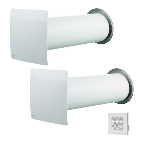
EQ 2 Product description The unit consists of a protecting internal grille with a decora- and foreign objects into the regenerator and the fan. The internal grille is equipped with manually actuated shut- tive panel, a cartridge, an air duct and a protecting external ters which can close the air duct during the unit standstill. - Page 9 In this operation mode, in case if two units are installed each of them operates two cycles in opposite phases. While one unit operates in air supply mode the other one operates in air extract mode. Example: 68 F 68 F EQ 2...
-
Page 10: Mounting And Set-Up
EQ 2 Mounting and set-up 5.1. WALL-MOUNTED CONTROL PANEL INSTALLATION AND CONNECTION Do not install the control panel on an Installation and connection of control panel shall only be performed by uneven surface! professional electrician. While tightening the screws, do not... - Page 11 Then connect the cable to the control panel in compliance with the wiring diagram, page 16. 4. Install the control panel display and press it to fix. EQ 2...
-
Page 12: 5.2. Unit Mounting
EQ 2 5.2. UNIT MOUNTING Read the user’s manual prior to moun- ting the unit. Do not block the air duct of the instal- led unit with dust accumulating mate- rials, such as curtains, cloth shutters, etc. As it prevents air circulation in the room. - Page 13 (accessories) Mark the sound-absorbing layer at the end of the air duct (1). Cut the excessive part of the sound-absorbing layer. Insert the adjusted and ready sound-absorbing layer into the air duct. No glue is required for fixation! EQ 2...
- Page 14 EQ 2 4. Insert the air duct in the wall. Fill the gaps between the wall Install the air duct with the sound-absorbing layer with and the opening with a mounting minimum slope 3° downwards using polystyrene wedges. foam or similar Fill the gaps between the wall and the opening with a mounting foam.
- Page 15 7. Install the internal grille and fix the external grille. External grille Internal grille with a decorative panel For mounting of the outer ventilation hood, please refer to a respective hood installation instruction. EQ 2...
-
Page 16: Connection To Power Mains And Control
EQ 2 Connection to power mains and control Disconnect the unit from power supply prior to any electric installation ope- rations. The following installation shall only be performed by a professional electrici- an according the instruction in the user manual. - Page 17 filter timer (factory setting 90 days) • emergency shutdown of the unit in case of a motor failure In case of power cut-off the set parameters are saved in the non-volatile memory of the control panel. EQ 2...
- Page 18 EQ 2 Unit control with a sensor control panel After expiry of the period set for the filter timer (factory setting 90 days) the FILTER contamination indicator starts glowing. In this case clean or replace the filters and reset the Timer filter timer.
-
Page 19: Technical Maintance
To access the basic assembly units follow the steps: Disconnect the socket connectors. Push the cable from the control panel aside to the wall and pull the cord from the cartridge to remove it from the air duct. Remove the filters from the cartridge. EQ 2... - Page 20 EQ 2 Clean the filters as they get contaminated, but not less than once in three months. • After expiry of the period set for the filter timer (factory setting 90 days) the filter replacement indicator appears on the control panel display.
-
Page 21: Troubleshooting
The unit can be carried in the original packing by any mode up at room temperature for at least 2 of transport provided proper protection against precipitation and mechanical damage. hours. EQ 2... -
Page 22: Ce Declaration Of Conformity
EQ 2 CE Declaration of conformity Compliance with valid versions of the following standards on This declaration confirms that the products meet the the date on which the declaration of conformity was signed: requirements in the following Council Directives and stand-... - Page 23 EQ 2...
- Page 24 Flexit AS, Televeien 15, N-1870 Ørje www.flexit.no...
Need help?
Do you have a question about the Eq 2 and is the answer not in the manual?
Questions and answers