Table of Contents
Advertisement
Advertisement
Table of Contents

Related Manuals for ALLEN & HEATH ANALOGUE ZONE Series


Summary of Contents for ALLEN & HEATH ANALOGUE ZONE Series
- Page 1 ALLEN&HEATH INSTALLATION & USER GUIDE ANALOGUE ZONE SERIES...
- Page 2 Limited One Year Manufacturer’s Warranty Allen & Heath warrants the Allen & Heath branded hardware product and accessories contained in the original packaging ("Allen & Heath Product”) against defects in materials and workmanship when used in accordance with Allen & Heath's user manuals, technical specifications and other Allen &...
-
Page 3: Table Of Contents
Contents Introduction ............................. 4 Packed Contents ..........................4 Front Panel ............................5 Input Section ..........................5 Output Section .......................... 6 General ............................. 7 Rear Panel ............................7 General ............................. 7 Control Section ......................... 8 Output Section .......................... 8 Input Section ..........................9 Installing GR4 ..........................10 Mounting the unit ........................10 Connecting to GR4 ........................11... -
Page 4: Introduction
Introduction 8in / 4out Zone Mixer The GR4 is a 1U rack-mounting or desktop audio mixer, providing simple comprehensive control of background music and paging in bars, restaurants, stores and other leisure / retail environments. Standout features include optional remote wall plates, a mic input on the front panel, plus a 3.5mm jack on the front for portable music sources. -
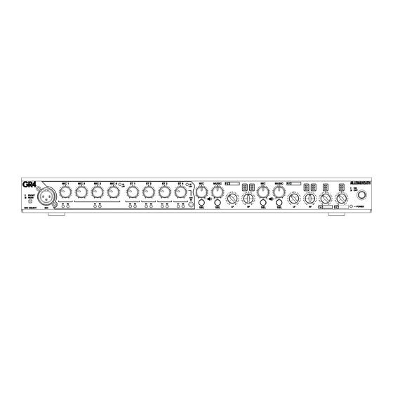
Page 5: Front Panel
Front Panel 3.1 Input Section ⑤ ⑤ ④ ③ ② ① ⑧ ⑥ ⑦ ①MIC SELECT – a user selectable switch for ⑥AUX INPUT – Auxiliary input on 3.5mm jack socket. MIC 1 input. MIC 1 signal can either be derived from the rear mount Euroblock or front mount This input will override any input connected XLR connectors. -
Page 6: Output Section
3.2 Output Section ③ ⑪ ⑯ ① ④ ⑧ ⑩ ⑱ ⑬ ⑮ ⑰ ⑥ ⑦ ⑫ ⑭ ⑨ ② ⑤ ①Z1 MIC MIX OUTPUT LEVEL – Adjustable ⑨Z2 MIC SELECT SWITCH – Output Zone rotary level control for MIC Mix to Zone 1. Mic selection switch used to add/remove mic Output level control Off to +6dB. -
Page 7: General
⑯Z3 OUTPUT METER - Three-segment LED ⑱Z4 OUTPUT METER - Three-segment LED meter showing mono output level of Zone 3 meter showing mono output level of Zone 4 Mix. Illumination will occur at -18, +3 and Mix. Illumination will occur at -18, +3 and +17dB. -
Page 8: Control Section
4.2 Control Section ②ALARM INPUT ② ③ Contact closure (DIP switch option for ① Normally Open/Closed) for emergency input detect. On activation all inputs will fade to the pre-set level except for Mic 1 and Z1 &Z2 LED’s will flash quickly. Normal operation will resume once contact is reset to original state. -
Page 9: Input Section
4.4 Input Section ① ② ③ ①STEREO INPUTS ③MIC INPUT ADJUSTMENT Line level inputs 1 to 4 on unbalanced phono Microphone gain, Lo and Hi EQ trim pots used connectors. to adjust the input sensitivity of the pre- amplifier channel* and to adjust the EQ setting Note: Unloaded Phono connectors can of the MIC channel. -
Page 10: Installing Gr4
Installing GR4 5.1 Mounting the unit The GR4 can be used as a stand-alone unit Using the small flat bladed screwdriver and placed on a hard surface or rack-mounted gently remove the four rubberized feet on in a standard 1U 19” profile. the base of the unit. -
Page 11: Connecting To Gr4
Connecting to GR4 6.1 Microphone Inputs Microphone inputs are balanced connections XLR to Euroblock (Balanced to Balanced) on Euroblock type connectors. 0 = Screen (Pin 1) Pin assignments are screen printed above the + = Hot (Pin 2) connector or alternatively use the below wiring - = Cold (Pin 3) diagram. -
Page 12: Zone Outputs
BALANCED SOURCE ST 1 (TRANSFORMER OR CROSS-COUPLED OUTPUT) XLR/Euroblock (Transformer or Cross- Coupled Output) to RCA Screen (Pin 1) = Link to Pin 3 Hot (Pin 2) = Tip Cold (Pin 3) = Sleeve Balanced to Unbalanced input wiring example. 6.3 Zone Outputs Zone outputs are balanced connections on Euroblock type connectors. -
Page 13: Alarm Input
Euroblock to RCA (Balanced to Unbalanced) 0 = Link to Negative + = Tip - = Sleeve Balanced line output (Phono) wiring example. 6.4 Alarm Input The Alarm input is a 2-pole connection on 2-Wire Alarm Contact Closure Euroblock type connector and is typically configured to the Normally Closed contacts. -
Page 14: Page Input
6.5 Page Input The Page input is a 2-pole connection on 2-Wire Paging Switch Euroblock type connector and is typically configured to the Normally Open contacts. 0 = COM Pin assignments are screen printed above the + = N/O (or N/C) connector or alternatively use the below wiring diagrams. - Page 15 Analogue Remote Connection 4-Wire Analogue Remote The analogue inputs are 4-pole Euroblock type connectors for Zone 1 & Zone 2 control. 0 = 0V These are 0-10V inputs and are typically used L = Level as a variable resistance and stepped voltage S = Source control for analogue volume control and + = 10V...
-
Page 16: Setting Up Gr4
Setting up GR4 7.1 Operating Features The GR4 is a feature rich analogue zone mixer. ‘Ducked’ signal the user can also control the Multiple configurations are possible by means hold time and release time of the compressor of internal jumpers, external dip switches and to suit the application. -
Page 17: Internal Jumper Settings
CAUTION 7.2 Internal Jumper Settings AC MAINS IN ~ FUSE TYPE AC SUPPLY 47-63Hz CAUTION 320VA MAX T 3.15A 20mm 220 - 240V~ 300W MAX T 5.0A 20mm 100 - 120V~ Please ensure that unit is switched off before changing any jumper settings Ensure SERIAL No: Made in the UK by ALLEN &... -
Page 18: Dip Switch Settings
Zone 3 & 4 are mixed from a matrix on internal jumpers. The unit is shipped with the below settings as default but both zones can have any number of jumpers applied to suit the application. Zone 3 & 4 Matrix Mix Default Positions 7.3 Dip Switch Settings There are 16 Rear mounted DIP switches for selecting various options. -
Page 19: Programming Parameters
7.4 Programming Parameters The GR4 has a total of 7 parameters (shown in Table 1) which are configurable by the installer/user. Each parameter has four pre-defined values which can be stepped through and set as required. Changing a Parameter Step by Step Guide- Ensure amplifiers/powered speakers are switched off prior to powering the unit up or down. -
Page 20: Faq
Q: What are the main differences connected in a ‘daisy-chain’ configuration. An optional PL-5 remote is also available for between the GR4 and GR2? Infrared control of the PL-14. Alternatively a A: The GR4 has an additional stereo zone custom or 3 party 0-10v controller can be output together with two additional mono zone wired to the “REMOTE Z1”... -
Page 21: Block Diagram
Block Diagram GR4 User Guide AP10223 Issue_2... -
Page 22: Specifications
Specifications Microphone Inputs Mic Input Sensitivity (Gain = Min) 0dBu Mic Input Sensitivity (Gain = Max) -50dBu Mic Level control (Max) +6dB Mic Level control (Min) Mic HPF -3dB 150Hz Mic EQ LF +/- 15dB fc = 60Hz Mic EQ HF +/-15dB fc = 9kHz Mic Frequency Response 20Hz –... -
Page 23: Connection Diagram
Connection Diagram GR4 User Guide AP10223 Issue_2... -
Page 24: Application Examples
Application Examples GR4 User Guide AP10223 Issue_2...
Need help?
Do you have a question about the ANALOGUE ZONE Series and is the answer not in the manual?
Questions and answers