Eliwell EWRC 300 NT Series User Manual
Controllers for static and ventilated cold rooms
Hide thumbs
Also See for EWRC 300 NT Series:
- User manual (89 pages) ,
- Quick start manual (17 pages) ,
- Quick start manual (16 pages)

Related Manuals for Eliwell EWRC 300 NT Series


Summary of Contents for Eliwell EWRC 300 NT Series
- Page 1 EWRC 300/500/5000 NT Controllers for static and ventilated cold rooms USER MANUAL www.eliwell.com...
- Page 2 Eliwell. You also accept to not create any hypertext links to this document or the relative contents. Eliwell shall not grant any rights or licence for personal and non-commercial use of the document and the relative contents, with the exception of a non- exclusive licence to consult the material “as-is”, at your own risk.
-
Page 3: Table Of Contents
CONTENTS 1. INTRODUCTION ......................9 1.1. GENERAL DESCRIPTION ...........................9 1.2. MODELS ................................9 2. TECHNICAL SPECIFICATIONS ................10 2.1. TECHNICAL DATA (EN 60730-2-9:2010, EN 61439-1:2011 / 61439-2:2011 / EN 60204-1:2006) ........10 2.2. ELECTRICAL SPECIFICATIONS .........................10 2.3. FURTHER INFORMATION ..........................11 2.3.1. INPUT CHARACTERISTICS ................................11 2.3.2. - Page 4 6. FUNCTIONS AND REGULATORS ................ 39 6.1. SETTINGS ................................39 6.1.1. PROBE SETTING AND CALIBRATION ............................39 6.1.2. DISPLAY SETTINGS ..................................39 6.2. FUNCTIONS .................................40 6.2.1. UPLOAD, DOWNLOAD, FORMAT ..............................40 6.2.2. UNICARD ......................................41 6.3. BOOT LOADER FIRMWARE ..........................42 6.4. COMPRESSOR ..............................43 6.4.1. COMPRESSOR CONFIGURATION ...............................43 6.4.2.
- Page 5 7. PARAMETERS ...................... 67 7.1. HOW TO MODIFY THE USER PARAMETERS ....................67 7.2. HOW TO EDIT THE INSTALLER PARAMETERS ....................67 7.3. PARAMETER TABLE ............................68 7.3.1. PARAMETER H60....................................78 8. ALARMS ....................... 79 8.1. ALARMS AND SIGNALS TABLE ........................79 8.2. ALARM CAUSE/EFFECT TABLE ........................80 8.3.
- Page 6 SAFETY INFORMATION Important information Read these instructions carefully and visually inspect the equipment to familiarise yourself with the device before attempting to install it, put it into operation, overhaul or service it. The following warning messages may appear anywhere in this documentation or on the equipment to warn of potential dangers or to call attention to information that can clarify or simplify a procedure.
- Page 7 The electrical panel (device) must be installed and repaired only by qualified staff. Neither Schneider Electric nor Eliwell accept any responsibility for any consequences resulting from the use of this material. A qualified person is someone who has specific skills and knowledge regarding the structure and the operation of electrical equipment and who has received safety training on how to avoid the inherent dangers.
- Page 8 Liability and residual risks The liability of Schneider Electric and Eliwell is limited to the correct and professional use of the product according to the directives referred to herein and in the other supporting documents, and does not cover any damage (including but not limited to) the following causes: •...
-
Page 9: Introduction
The container lets you install one or more electromechanical devices, depending on the model. This summary document contains basic information about the standard EWRC 300/500/5000 NT models. For further information and custom configurations, refer to the complete user manual code 9MA0258, available to download from the website www.eliwell.com. 1.2. MODELS •... -
Page 10: Technical Specifications
2. TECHNICAL SPECIFICATIONS 2.1. TECHNICAL DATA (EN 60730-2-9:2010, EN 61439-1:2011 / 61439-2:2011 / EN 60204-1:2006) Front panel protection rating IP65 Classification: Electronic automatic control device (not safety device) for stand-alone installation Installation: wall Type of action: Pollution class: Panel use: Internal use Panel type: Fixed panel... -
Page 11: Further Information
2.3. FURTHER INFORMATION 2.3.1. INPUT CHARACTERISTICS Measurement range: NTC: -50.0...110°C (-58°F...230°F); (on 3-digit display with +/- sign) PTC: -55.0...150°C (-67°F...302°F); (on 3-digit display with +/- sign) Accuracy: better than 0.5% integral scale + 1 digit Resolution: 0.1°C (0.1°F) Buzzer: only on models where this is provided Analogue inputs: 3(2) configurable NTC/PTC inputs Digital inputs:... -
Page 12: Mechanical Characteristics
2.3.3. MECHANICAL CHARACTERISTICS Casing: PC+ABS EWRC 300/500 Dimensions: front panel 213 x 318 mm, depth 102 mm EWRC 500 BREAKER front panel 221 x 318 mm, depth 107 mm EWRC 5000 front panel 420 x 360 mm, depth 147 mm Terminals: screw See “4.1.2. -
Page 13: Mechanical Installation
3. MECHANICAL INSTALLATION 3.1. Before starting Before starting to install your system, read this chapter carefully. Caution must be exercised concerning compliance with all safety information, other electrical requirements or laws which may apply to your machine or process when using this equipment. WARNING REGULATORY INCOMPATIBILITY Make sure that all equipment used and the systems designed comply with all applicable local, regional and national laws. - Page 14 WARNING UNINTENDED EQUIPMENT OPERATION Install and use the equipment in compliance with the conditions described in the Technical Specifications chapter. Failure to follow these instructions can result in death, serious injury, or equipment damage. 3.4. Comments concerning installation WARNING UNINTENDED EQUIPMENT OPERATION •...
-
Page 15: Installation Procedure
3.5. INSTALLATION PROCEDURE NOTE: procedural steps that are common to all models. ONLY the EWRC 5000 model is used as an example. Remove the cover and drill the holes for the cable clamps (at least one for power cables and one for signalling cables) on the bottom of the panel. - Page 16 Optional. Install the plug-in RS-485 module for communication with the supervisor. EWRC 5000 only: 1) Remove the seven screws securing the plastic protecting the board. 2) Remove the protective element, then use a box cutter to remove the two terminal covers. 3) Connect the RS-485 plug-in module (optional) using the specific spacers, then replace the cover and secure it using the screws.
- Page 17 Make the electrical connections referring to the wiring diagrams shown page 24 and page 25. Use suitable cable/pipe clamps. NOTE: only models with magnetothermal switch. Connect the switch to the electronic board power supply using the accessory cable provided in the packaging. Fit the hinges to secure the cover.
- Page 18 DIN rail-mounted models with window only. Close access to inside the panel from the front window using the dedicated DIN plugs. For EWRC NT 500 models with the plastic knockout removed and no internal magnetothermal switch, the end user is responsible for ensuring that the open parts of the box are not accessible.
- Page 19 WARNING UNINTENDED EQUIPMENT OPERATION • Place the devices dissipating the most heat in the top of the cabinet and ensure suitable ventilation. • Do not place this equipment near or above any devices which could cause overheating. • Install the device in a point that guarantees the minimum distances from all structures and adjacent equipment as indicated in this document.
-
Page 20: Electrical Connections
4. ELECTRICAL CONNECTIONS 4.1. Wiring practices The following information describes the guidelines for wiring and the associated best practices to follow when using the device. DANGER HAZARD OF ELECTRIC SHOCK, EXPLOSION OR ARC FLASH • Disconnect all power from all equipment including connected devices prior to removing any covers or doors, or installing or removing any accessories, hardware, cables or wires. -
Page 21: Rules For Screw-Type Terminal Boards
4.1.2. Rules for screw-type terminal boards The table below illustrates the types of cables and wire sections for a screw-type terminal board with5.08 (0.197 in.) spacing: 0.28 2 x 0.5...1.5 0.2…2.5 0.2…2.5 0.25…2.5 0.25…2.5 2 x 0.2…0.75 2 x 0.2…0.75 2 x 0.25…0.75 2 x 20...16 24…14... -
Page 22: Analogue Inputs-Probes
Specific considerations for handling When handling the equipment, use caution to avoid damage caused by electrostatic discharge. In particular, the unshielded connectors and in certain cases the open circuit boards are vulnerable to electrostatic discharge. WARNING UNINTENDED EQUIPMENT OPERATION DUE TO ELECTROSTATIC DISCHARGE •... -
Page 23: Serial Connections
Failure to follow these instructions can result in equipment damage. 4.1.6. TTL connection Use a 5-wire TTL cable up to 3 m (118 in.) in length. An Eliwell-supplied TTL cable is recommended. Contact Eliwell Sales Office for item availability. 9MA10258.01 07/2018... -
Page 24: Wiring Diagram
4.2. WIRING DIAGRAM EWRC 300/500/5000 NT Yellow cable UNICARD COPY CARD DISPLAY RS-485 OPTIONAL EWRC 500NT/ 5000 NT only OUT1 OUT2 OUT3 OUT4 OUT5 20 21 RCSU RCSH Pb1 Pb2 DI2 DI1 RCH300 230 Vac Pb3/DI3 20 21 RCSP RCAP 230 Vac 4.2.1. -
Page 25: Wiring Diagram For Models With Magnetothermal Switch Installed
4.3. WIRING DIAGRAM FOR MODELS WITH MAGNETOTHERMAL SWITCH INSTALLED EWRC 500 NT BREAKER OUT1 OUT2 OUT3 OUT4 OUT5 20 21 RCAU Pb1 Pb2 DI2 DI1 16 A max Pb3/DI3 20 21 RCAP 230 Vac 4.3.1. TERMINALS TERMINALS 1, 5, 8 9, 10 LINE/NEUTRAL. -
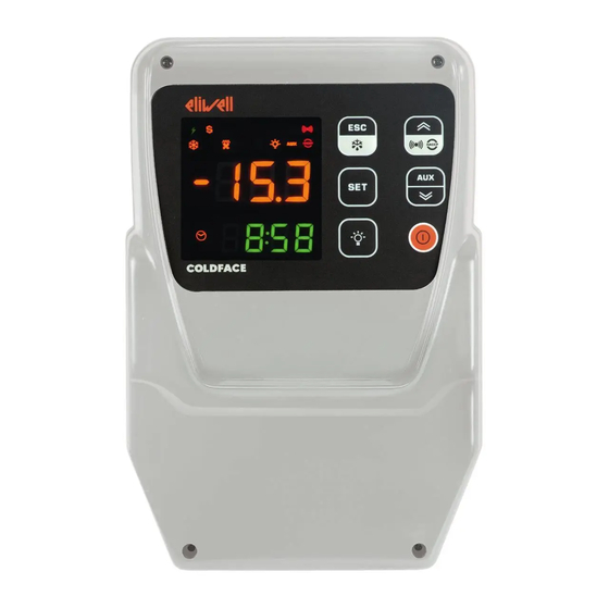
Page 26: User And Start-Up Interface
5. USER AND START-UP INTERFACE 5.1. DISPLAY 5.1.1. KEYS press and hold for about press and release NAVIGATION MENU Notes 3 seconds • Manual defrost Configurable - see parameter H33 • Functions Menu • Output Defrost • Return to Main Menu HACCP alarms p UP •... -
Page 27: Icons
5.1.2. ICONS Icons have the following meaning: ICON colour description amber not used TIME amber access in case of time display or editing DATA amber access in case of date display or editing Alarms ICON 7 ICON 8 Colour Buzzer Icon Buzzer ALARM... -
Page 28: Preliminary Configurations
5.1.3. PRELIMINARY CONFIGURATIONS After making the electrical connections, simply power up the device to start operation. At first start-up, Eliwell recommends that you: make sure the instrument is powered (green POWER SUPPLY icon on) make sure the display is working: when the controller is powered up it performs a lamp test, during which time the display and icons will blink for several seconds to ensure that they all function correctly make sure there are no active alarms (ALARM / HACCP ALARM icon off and labels E1, E2, E3 not displayed). -
Page 29: Navigation
5.1.5. NAVIGATION Display alarms SetPoint & Probes display probe display probe if active Turns light on/o value value Display HACCP alarms Turns instrument -20.6 -20.6 if function active on / o 1 sec set time and date 18.55 3 sec Manual 1 sec modify SetPoint... -
Page 30: Functions Menu And Key-Enabled Functions
5.1.6. FUNCTIONS MENU AND KEY-ENABLED FUNCTIONS The Functions menu is used to perform a number of manual functions such as putting the device into stand-by, clearing pressure switch interventions and clearing HACCP alarms, etc. Access the Functions menu by pressing the ESC key. The following table lists the functions, which are all OFF by default. -
Page 31: Passwords
5.1.7. PASSWORDS Password PA1 is disabled by default. Password “PA1”: allows access to User parameters. To enable (PA1≠0): press and hold SET for more than 3 seconds. The label USr appears. Press SET again. Scroll through the parameters using UP and DOWN until you find label PA1, press SET to display its value, change it using UP and DOWN and save by pressing SET or ESC. -
Page 32: Setpoint Programming
Display description Press SET Use UP and DOWN keys to enter the password In the example the password is 15 Press SET Installer menu accessed the first CPr folder appears If the value entered is incorrect, label PA2 will be shown again and the procedure must be repeated 5.1.8. -
Page 33: Viewing Probe Values
5.1.9. VIEWING PROBE VALUES Display description -17.8 Press and release the SET key -20.0 The upper display will show SEt, the lower display will indicate the current setpoint value -20.0 Use the DOWN key to view the value of probe Pb1 The time is displayed in HACCP models 5.28 Use the DOWN key again to view the value of... -
Page 34: How To Modify The Date And Time
5.1.10. How to modify the date and time Function only available in HACCP models Display description -17.8 Press and release the SET key -20.0 The upper display will show SEt, the lower display will indicate the current setpoint value -20.0 Use the DOWN key to display the time The CLOCK icon will be on 5.28... -
Page 35: Displaying Alarms
5.1.11. Displaying Alarms Display description -17.8 Press and release the UP key. The upper display will show ALr. -18.0 The lower display will show nOnE a. nOnE if no alarms active b. SYSt if system alarms present SYSt HACCP models ONLY The upper display will show ALr. -
Page 36: System Alarms Example
5.1.12. System Alarms example Let us suppose two alarms have occurred, • one HIGH TEMPERATURE on the cold room probe • one HIGH TEMPERATURE on probe 3 (parameter H43 different from 0) Display description -17.8 Press and release the UP key. -18.0 The upper display will show ALr. -
Page 37: Modifying A Parameter
5.1.13. Modifying a parameter The User parameters USr are not divided into subfolders. They are always visible by default (access password PA1 is not enabled by default). The same parameters are also visible in the respective folders ‘Compressor’, ‘Fans’, etc. within the Installer parameters menu InS. - Page 38 How to modify an Installer parameter Instructions are provided below on how to modify the same User parameter but via the Installer menu Let us take the dit parameter as our example. At Installer level the parameter is in the folder containing dEF defrost parameters. We will now show how to change the value from 8 h to 6 h.
-
Page 39: Functions And Regulators
6. FUNCTIONS AND REGULATORS This chapter describes the various functions of the devices. NOTE: some functions may not be available in certain models. 6.1. SETTINGS 6.1.1. PROBE SETTING AND CALIBRATION EWRC 300/500/5000 NT have 3 configurable NTC/PTC inputs (Pb1...Pb3). The temperature probes (Pb1...Pb3) must all be the same type and should be configured via parameter H00, visible at User level (USr) or inside folder CnF, Installer level (inS) •... -
Page 40: Functions
6.2. FUNCTIONS 6.2.1. UPLOAD, DOWNLOAD, FORMAT Description The Unicard/CopyCard must be connected to the (TTL serial port and allows the rapid programming of instrument parameters. DOWNLOAD from reset operating mode: at power-on, if the Unicard/CopyCard is inserted in the device, the controller automatically downloads data. -
Page 41: Unicard
6.2.2. UNICARD The Unicard lets you download/upload a parameter map from/to a controller, in the same way as the CopyCard. It is a versatile tool that also allows you to quickly and easily customise devices. It differs from the Copy Card in the following ways: 1) it can be connected to a computer via USB 2) it can be plugged into a USB socket or USB battery, to power the device directly during upload/download. -
Page 42: Boot Loader Firmware
6.3. BOOT LOADER FIRMWARE The device is equipped with a Boot Loader, so it is possible to update the Firmware directly on site. Updating may be carried out using UNICARD or CopyCard (CopyCard). Updating procedure: • Connect the UNICARD/CopyCard equipped with the application; •... -
Page 43: Compressor
6.4. COMPRESSOR The compressor is controlled by the device’s relay. It will be switched on or off depending on: • the temperature status readings from the cold room probe • the temperature control functions set • the defrost/dripping functions (see Defrost chapter) 6.4.1. -
Page 44: Compressor/General Protections
6.5. COMPRESSOR/GENERAL PROTECTIONS Description If the cold room probe is in error E1 the output relay configured as compressor/general regulates in accordance with the times set in parameters Ont and OFt. The first time to consider is Ont. If Ont >0 the protection programmed in parameters dOn-dOF-dbi (see safety compressor times). -
Page 45: Compressor Safety Timings
6.5.1. Compressor safety timings Compressor on-off operations must respect the safety times that you can set using the special parameters as described below. The compressor icon will flash to indicate when a compressor activation request has been received but a safety protection exists. -
Page 46: Defrost/Dripping
User parameters The parameters that manage this regulator are: Label Description Compressor output ON time in the event of a faulty Pb1 probe Compressor output OFF time in the event of a faulty Pb1 probe Compressor output activation delay from request Compressor output activation delay from shutdown Delay between two consecutive starts of the compressor output Output activation delay from power-on... -
Page 47: Automatic Defrosting
6.6.2. Automatic defrosting The defrost cycle is programmed to start at intervals. NOTE: To disable the automatic cycle, set dit=0. If dit>0, the defrost cycles will be run at fixed intervals, as indicated in parameter dit and the interval time is counted as follows: Par. -
Page 48: External Defrost
6.6.4. External defrost If the Digital Input is configured for this function (if H11...H13 = 1) and if conditions permit, defrost can be requested and the corresponding regulator activated. Time graphs for signals in each of the various function modes are presented below. NOTE: Defrost activation occurs when the signal is toggled and the polarity can be selected. -
Page 49: Defrost With Remote Start/Stop
6.6.5. Defrost WITH REMOTE START/STOP If the Digital Input is configured for this function (if H11...H13 = ±22) defrost with start/stop is activated from remote. The defrost is switched on when the digital input becomes active. Vice versa, when the digital input is disabled, the defrost ends. -
Page 50: Defrost Mode
6.7. DEFROST MODE 6.7.1. Defrost with electric heaters Defrost with electric heaters is configured via parameter dtY = 0. The compressor remains stopped for the duration of the defrost cycle and the relay configured as defrost regulator output, to which the electric heaters are connected, activates. On completion of defrost, the electric heaters are switched off and the compressor remains off for the dripping time set in parameter dt, if it is not equal to zero. -
Page 51: Inverse Defrost
6.7.2. Inverse defrost Hot gas defrost is configured by setting parameter dtY = 1. The compressor stays on for the entire duration of the defrost cycle and the relay configured as defrost regulator output, and that the solenoid valve is connected to, activates. On completion of the defrost cycle, the valve relay is de-energised and the dripping phase set in parameter dt (if not equal to zero) is interrupted. -
Page 52: Double Evaporator Defrost
6.7.3. Double evaporator defrost The defrost for a second evaporator can be controlled via the probe configured as second evaporator. Configure a relay output (see configuration parameters H21…H25) as a defrost relay for evaporator 2. To enable this function, you need to: •... - Page 53 User parameters The parameters that manage this regulator are: Label Description Selects defrost type Time interval between 2 consecutive defrost cycles Selects the count mode for the defrost interval Defrost cycle activation delay after request Defrost timeout evaporator 1. Determines the maximum defrost duration Defrost timeout evaporator 2.
-
Page 54: Evaporator Fans
6.8. EVAPORATOR FANS 6.8.1. Evaporator fan operating conditions The regulator is active when: • the time set in parameter OdO has elapsed. • the temperature of the evaporator probe, if present, is between the values of parameters Fot and FSt •... -
Page 55: Fan Operation In Temperature Control Mode
The graphs below illustrate fan operation on the basis of the FCO value. In the graphs, we can see that: COOL COOL PROBE OK PROBE OK Fon/FoF PROBE KO PROBE KO COOL COOL PROBE OK Fon/FoF PROBE OK Fon/FoF PROBE KO Fon/FoF PROBE KO COOL... -
Page 56: Fan Operation In Duty-Cycle Mode
°C (Pb3) 6.8.3. Fan operation in Duty-Cycle mode For Duty-cycle operation, parameters Fon and FoF must be set accordingly; The fans operate as follows: DUTY-CYCLE Fan operation ≠0 ≠0 DUTY-CYCLE ≠0 ≠0 The fan regulator will operate in Duty-cycle mode as illustrated below: DUTY-CYCLE 9MA10258.01 07/2018... -
Page 57: Fan Operation In Defrost
6.8.4. Fan operation in defrost During defrost, the fans operate as shown in this diagram dFd = n: the fans are not excluded during defrost TEMPERATURE CONTROL / DUTY-CYCLE (see parameters FCO, Fon, FoF) dFd = y: exclusion of fans during defrost Thermostat control of fans takes place at the values set in parameters: •... -
Page 58: Fan Function During Dripping
6.8.5. Fan function during dripping If parameter dt ≠ 0 (dripping time), the fans will stay OFF for the time set in this parameter. See “Defrost with electric heaters”. Note that if Fdt (fan delay time) is greater than dt (dripping time) the fans stay OFF for the time set in Fdt rather than dt (e.g. -
Page 59: Deep Cooling Cycle - Dcc
6.9. DEEP COOLING CYCLE - DCC Description This regulator ensures that the compressor regulates the setpoint dCS, with differential equal to the value set via parameter diF. When the DCC (Deep Cooling Cycle) activates, the interval between defrost cycles is cleared and defrosts are disabled. Ending of the DCC is time-based, by setting the parameter tdc≠0, or when the setpoint dCS if tdc = 0. -
Page 60: Pressure Switch
6.11. PRESSURE SWITCH This regulator performs diagnostic procedures on an activated digital input by assigning the value ±11 (General pressure switch), ±09 (Minimum pressure switch) or ±10 (Maximum pressure switch) to one of the parameters H11...H13. If a pressure switch input is activated, power to the compressor loads is immediately cut off, the corresponding alarm icon lights up to provide a visual warning and the alarms folder ALr is also displayed. -
Page 61: Auxiliary Output (Aux/Light)
6.11.1. AUXILIARY OUTPUT (AUX/LIGHT) Description If one of the parameters H21...H25 is set to the value H2x=5, it anticipates the relay control as AUX and, by pressing the associated key H32...H35 which must be set to the value H3x=2, the relay is activated if it was off previously and vice-versa. The on/off status is saved in non-volatile memory hence when power returns after a blackout, the device will restart in the status that was active prior to the blackout. -
Page 62: Door/External Alarm Management
6.12. DOOR/EXTERNAL ALARM MANAGEMENT The door switch input is associated to an appropriately configured digital input (H1x = ±4). By controlling the opening of the door, it is possible to disable the compressor output and/or the fans. It is also possible to associate a deactivation delay with the compressor output by means of parameter dCO. If the door is opened during a defrost cycle, the cycle is not shut down. - Page 63 9MA10258.01 07/2018...
-
Page 64: Demisting Heaters (Frame Heaters)
6.13. DEMISTING HEATERS (FRAME HEATERS) The controller is equipped with a regulator for the demisting heaters. Operating conditions The table below lists the ways the relay output can be managed: FRAME HEATER OUT >0 >0 >0 >0 Duty-cycle Where HOn = 0 the regulator is always off, while if HOn > 0 and HOF = 0 the regulator is always on. If HOn >... -
Page 65: Condenser Fans
6.14. CONDENSER FANS This regulator is associated with probe Pb3 (see specific section) and features: • intervention setpoint SCF • operating differential dCF • exclusion of fans during defrost dCd • activation delay after end of defrost tCF If a digital output is set as condenser fans (H21...H25=12), this output will behave as follows: SCF-dCF °C If probe Pb3 is not present and if alarm E3 is active, the regulator will always be active except during the defrost cycle. -
Page 66: Stand-By
6.15. STAND-BY Operating conditions The stand-by regulator can be activated by digital input (if configured) or by key (if programmed). With the device OFF the display shows “OFF” and all regulators are blocked including alarms. When the device is switched on via a key or an appropriately configured digital input, regular operation commences, the same as from power-on. -
Page 67: Parameters
7. PARAMETERS 7.1. HOW TO MODIFY THE USER PARAMETERS The ‘User’ parameters are the most useful ones. This document describes them in the Parameter Table section. 1) Press and hold the SET button for at least 3 seconds, until the display shows USr 2) Press and release the SET key. -
Page 68: Parameter Table
7.3. PARAMETER TABLE PAR. LEV. DESCRIPTION U.M. RANGE DEFAULT USr/inS Temperature control SEtpoint °C/°F -58.0...302 COMPRESSOR parameters (CPr) Activation differential USr/inS °C/°F 0...30.0 N.B.: diF cannot be equal to 0. Maximum value that can be assigned to the setpoint. USr/inS NOTE: The two setpoints are interdependent: HSE cannot be less than LSE °C/°F LSE...HdL... - Page 69 PAR. LEV. DESCRIPTION U.M. RANGE DEFAULT Defrost interval count mode 0 = compressor running time (DIGIFROST® method); defrost active ONLY when compressor is on. N.B.: compressor running time is counted separately from the evaporator probe (count active even if the evaporator probe USr/inS absent or error).
- Page 70 PAR. LEV. DESCRIPTION U.M. RANGE DEFAULT Setting the time for defrosts on weekends/public holidays If parameter dit (defrosting interval) is dit = 0, dCt = 3 and the RTC option is declared present, then parameters F1...F8 allow you to set the hours and minutes. Only on the basis of these values will a defrost cycle begin.
- Page 71 PAR. LEV. DESCRIPTION U.M. RANGE DEFAULT Evaporator fans operating mode. The status of the fans will be: COMPRESSOR COMPRESSOR Notes Thermostat controlled Thermostat controlled Thermostat controlled USr/inS 0...4 Thermostat controlled Thermostat controlled controlled via parameters Thermostat controlled duty-cycle FOn and FOF controlled via parameters Thermostat controlled duty-cycle...
- Page 72 PAR. LEV. DESCRIPTION U.M. RANGE DEFAULT Enables alarm relay in the event of probe 3-related alarms: 0 = does not enable alarms in the event of alarms/errors on probe 3 0...2 1 = enables the alarm relay in the event of alarms/errors on all probes 2 = enables the alarm relay ONLY in the event of alarms/errors on probe 3 Regulator alarm type.
- Page 73 PAR. LEV. DESCRIPTION U.M. RANGE DEFAULT Start of event hours/minutes. Sets event start time based on the value of E0. The “NIGHT” mode begins at this time. The duration is determined by parameter E2 In hours and minutes (in the parameter table, the parameter is split into E1_h (hours), E1_min (minutes)) Duration of event.
- Page 74 PAR. LEV. DESCRIPTION U.M. RANGE DEFAULT Baudrate selection. 96 (0) = 9600 192 (1) = 19200 384 (2) = 38400 DISPLAY parameters (diS) LOCk. Setpoint edit lock. The parameter programming menu can still be accessed, and the settings changed, which means also that the status of this parameter can USr/inS be changed so as to unlock the keypad.
- Page 75 PAR. LEV. DESCRIPTION U.M. RANGE DEFAULT “Instant” maximum HACCP alarm indication threshold: when the temperature value read by the temperature control probe goes beyond the range set in “SHi”, °C/°F SHH...150.0 35.0 an HACCP alarm is immediately triggered, with the icon/(alarm relay) coming on according to parameter H50 (see specific section).
- Page 76 PAR. LEV. DESCRIPTION U.M. RANGE DEFAULT Configuration of digital input 1/polarity. NOTE: - The “+” sign indicates that the input is active when the contact is closed - The “−” sign indicates that the input is active when the contact is open ±10 = Maximum pressure switch 0 = disabled ±11 = General pressure switch...
- Page 77 PAR. LEV. DESCRIPTION U.M. RANGE DEFAULT Setpoint for Pb3-Pb1 temperature differential. Sets the Pb3-Pb1 differential If H43=3-1, regulation of the temperature differential between probes Pb3 and Pb1, in addition to regulation of probe Pb1, is enabled. In this way, to activate compressor regulation, one or both of the two conditions must be met (on Pb1 or Pb3-Pb1 °C/°F 0...255...
-
Page 78: Parameter H60
7.3.1. Parameter H60 Display of selected application. 0=no vector selected; 1= application 1, …, 6= application 6. It has a subset of parameters which can be programmed in line with the type of configuration required for the installation. By setting H60, the user can also select one of the six ‘sets’ of pre-programmed parameters. If you do not want to enable any of the available setpoints, but prefer to use the programming menu values, simply set parameter H60 to 0. -
Page 79: Alarms
8. ALARMS 8.1. ALARMS AND SIGNALS TABLE When an alarm condition is detected, the ALARM icon will come on If present and enabled, the buzzer and alarm relay will also activate. To silence the buzzer, press and release any key, the relative icon will continue to flash. All alarms are reset automatically (i.e. -
Page 80: Alarm Cause/Effect Table
8.2. ALARM CAUSE/EFFECT TABLE EWRC 300/500/5000 NT can run integral diagnostics on the installation, signalling any operating faults with specific alarms found, and record and signal any user-defined unusual events to have greater control over the system as a whole. Label Description Cause Effects... - Page 81 Label Description Cause Effects Remedy If the number n of pressure switch activations Alarm Check and remove external cause of Pressure switch alarm activation by general n<PEn: general pressure alarm on DI pressure switch regulator. • Number of pressure switch activations switch (Automatic Reset).
-
Page 82: Description Of Alarms
8.3. DESCRIPTION OF ALARMS 8.3.1. PROBE alarm OPERATING CONDITIONS When one of the probes is out of the nominal operating range or in the case of an open probe or a probe in short circuit, an alarm is generated if this condition persists for longer than 10 seconds. The alarm condition is indicated on the display by means of the following error codes: •... -
Page 83: Minimum And Maximum Temperature Alarm
8.3.2. MINIMUM AND MAXIMUM TEMPERATURE alarm OPERATING CONDITIONS The alarm regulation is carried out on probe 1. The temperature limits defined in parameters HAL and LAL are determined by parameter Att which specifies if they represent the absolute temperature value or a setpoint differential (in the case of offset on the entered setpoint, the high and low alarms will refer to this new control set point). -
Page 84: End Of Defrost Due To Timeout Alarm
HIGH AND LOW TEMPERATURE ALARM OPERATION WITH DOOR OPEN • If Art = 0 (regulation of temperature alarms disabled with door open) 1. If the door is open and there is no temperature alarm, the alarms are inhibited and cannot be activated;... -
Page 85: External Alarm
8.3.4. EXTERNAL alarm OPERATING CONDITIONS In the case of activation of the digital input, the alarm regulator is activated with the delay set by parameter dAd, and this alarm persists until the next time the digital input is deactivated. The action consists of: •... -
Page 86: Pressure Switch Input Alarm
SIGNALLING Code Meaning Door open alarm USER PARAMETERS Label Description Digital input for switching off loads: 0 = disabled; 1 = disables the fans; 2 = disables the compressor; 3 = disables fans and compressor. Compressor activation delay from acknowledgement Open door disabling time 8.3.6. -
Page 87: Panic Alarm
8.3.7. PANIC alarm OPERATING CONDITIONS The panic alarm is associated to a specially configured digital input: • H11, H12, H13 = ± 18 After the delay set in parameter dAd, this alarm is activated and persists until the next digital input deactivation. The action consists of: •... - Page 88 SIGNALLING Code Meaning Leak Detector Alarm USER PARAMETERS Label Description Activation delay DI1, DI2 Activation delay DI3 9MA10258.01 07/2018...
-
Page 89: Modbus Msk 554 Functions And Resources
The master device can send messages to individual slaves or to the entire network (broadcast) whilst slaves can only respond individually to the master. The ModBUS standard used by Eliwell employs the RTU code for data transmission. 9.3.1. DATA FORMAT (RTU) The coding model used defines the structure of messages transmitted on the network and the way in which this information is deciphered. -
Page 90: Modbus Commands Availble And Data Areas
9.3.3. ModBUS COMMANDS AVAILBLE AND DATA AREAS The following commands are implemented: ModBUS command Command description 03 (hex 0x03) Read 16 consecutive registers for Client side. 04 (hex 0x04) Read 1 single register for parameters. 16 (hex 0x10) Write 15 consecutive registers for Client side 22 (hex 0x16) Write 1 register for the parameters 43 (hex 0x2B) -
Page 91: Parameter Visibility And Values
9.3.5. PARAMETER VISIBILITY AND VALUES NOTE: 1) When not indicated otherwise, the parameter is always visible and modifiable, unless customised settings have been configured by the user via serial 2) If folder visibility is modified, the new setting will apply to all parameters in the folder. 9.3.6. - Page 92 Examples (in binary form the least significant bit is the first on the right): Default visibility: PAR. VALUE ADDRESS DATA SIZE Value Content of register 49336.6 2 BIT 65535 -------------(000000001111111111111111) 49337 2 BIT 65535 (000000001111111111111111) 49337.2 2 BIT 65535 (000000001111111111111111) 49337.4 2 BIT 65535...
-
Page 93: Parameter/Visibility Table
9.3.7. PARAMETER/VISIBILITY table NOTE: ModBUS read command: 04 (0x04) and ModBUS write command: 22 (0x16) 16386 49455 Setpoint WORD °C/°F LSE...HSE 16388 49455,2 Setpoint differential WORD °C/°F 0...30.0 16390 49455,4 Maximum setpoint value that can be set WORD °C/°F LSE...HdL 16392 49455,6 Minimum setpoint value that can be set... - Page 94 dE8_h 49355 Defrost start time (minutes) no. 8 weekday BYTE hours 0...24 dE8_min 49354 Weekday defrost 3 duration BYTE 0...59 F1_h 49357 Defrost start time (hours) no. 1 weekend BYTE hours 0...24 F1_min 49356 Defrost start time (minutes) no. 1 weekend BYTE 0...59 F2_h...
- Page 95 Enables alarm relay in the event of probe 3-related 49277 49471,2 BYTE 0/1/2 alarms 16655 49491,4 Regulator alarm type BYTE 49278 49471,4 Enable light relay from door switch BYTE flag 49279 49471,6 Light relay deactivation delay BYTE 0...31 49280 49472 Light key always disables light relay BYTE flag...
- Page 96 d6_E1_h 49409 Event start time (hours) day 7 BYTE hours 0...23 d6_E1_m 49408 Event start time (minutes) day 7 BYTE 0...59 d6_E2 49386 Event duration day 7 BYTE hours 0...72 d6_E3 49394 Enable defrost weekdays or weekends day 7 BYTE flag 0...1 d7_E0...
- Page 97 16454 49483,4 DI2 input configuration BYTE -22...22 49483,6 16456 DI3 input configuration BYTE -22...22 49311 49484,2 Configuration relay 1 BYTE 0...13 49312 49484,4 Configuration Relay 2 BYTE 0...13 49313 49484,6 Configuration Relay 3 BYTE 0...13 49314 49485 Configuration Relay 4 BYTE 0...13 49315...
-
Page 98: Parameter/Visbility H60 Table
9.3.8. PARAMETER/VISBILITY H60 table 16752 Regulation set point WORD °C/°F LSE...HSE V0-SEt 16754 Setpoint differential WORD °C/°F 0.1...30.0 V0-diF 16756 Minimum setpoint value that can be set WORD °C/°F LSE...HdL V0-LSE 16758 Maximum setpoint value that can be set WORD °C/°F LdL...HSE V0-HSE... - Page 99 49585 Evaporator fans disabling during defrost time BYTE flag V2-dFd 16818 Regulation set point WORD °C/°F LSE...HSE V3-SEt 16820 Setpoint differential WORD °C/°F 0.1...30.0 V3-diF 16822 Minimum setpoint value that can be set WORD °C/°F LSE...HdL V3-LSE 16824 Maximum setpoint value that can be set WORD °C/°F LdL...HSE...
-
Page 100: Folder Visibility Table
9.3.9. FOLDER VISIBILITY TABLE ModBUS DATA LABEL DESCRIPTION RANGE ADDRESS SIZE 49450 Folder visibility 2 bit 0...3 vis_CPr 49450,2 Folder visibility 2 bit 0...3 vis_dEF 49450,6 Folder visibility 2 bit 0...3 vis_FAn 49451 Folder visibility 2 bit 0...3 vis_ALr 49451,2 Folder visibility 2 bit 0...3... - Page 101 DATA- LABEL ADDRESS DESCRIPTION RANGE SIZE COMP1 33092,3 Compressor 1 1 bit 0...1 flag COMP2 33099,4 Compressor 2 1 bit 0...1 flag FAN_EVAP 33094,7 Evaporator fans 1 1 bit 0...1 flag FAN COND 33102,7 Condenser 1 fans 1 bit 0...1 flag DOOR 33096,3...
-
Page 102: Advanced Functions - Night And Day
10. ADVANCED FUNCTIONS - NIGHT AND DAY Events and cycles can be programmed at set times during the week using the Night&Day regulator algorithm. The parameters concerned are contained in folder nAd / subfolders d0…d6, Ed NOTA: do not confuse labels E0 … E3 with probe error messages E1 … E2… NOTE: be careful as to how E0 = 3 (stand-by regulator) is used. -
Page 103: Operation With Defrost Group
10.2. OPERATION WITH DEFROST GROUP If E0 is not equal to 0, the meaning of weekday parameters dE1…dE8 shifts from: Defrost group valid EVERY day (see Automatic defrost with Real Time Clock.) Defrost group applicable only to weekdays. The weekday parameters dE1…dE8 are supplemented with the management of weekend/public holiday parameters F1…F8. -
Page 104: Opening Folder Nad - Day/Night
10.4. OPENING FOLDER NAD - DAY/NIGHT Display description -17.8 Press SET for 3 seconds -18.0 Folder USr appears Use the UP & DOWN keys to search for the InS folder Press and release the SET key Use the UP & DOWN keys to search for the nAd folder Press and release the SET key. -
Page 105: Advanced Functions - Haccp
11. ADVANCED FUNCTIONS - HACCP To meet the minimum requirements prescribed in HACCP regulations, there is a set of dedicated parameters. These parameters can be viewed and configured in folder: HACCP (folder with label “HAC”) The recording of HACCP alarms can be enabled in parameter H50≠0 NOTE. -
Page 106: Displaying Haccp Alarms
11.1. DISPLAYING HACCP ALARMS Display description The red HACCP icon will remain permanently on to indicate an HACCP alarm has occurred Press and release the UP key The upper display will show ALr HACP If HACP alarms have occurred the lower display will show HACP Press and release the SET key To access the information contained within each AHC folder, press the ‘set’... - Page 107 Technical Customer Support T +39 0437 986 300 E techsuppeliwell@schneider-electric.com Sales T +39 0437 986 100 (Italy) T +39 0437 986 200 (other countries) E saleseliwell@schneider-electric.com 9MA10258.01 - EWRC300/500/5000 NT - EN - 07/18 © 2014-2018 Eliwell. All rights reserved...
Need help?
Do you have a question about the EWRC 300 NT Series and is the answer not in the manual?
Questions and answers