Eliwell EWRC 500 NT Quick Start Manual
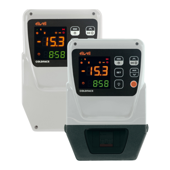
Controllers for static and ventilated cold rooms
Hide thumbs
Also See for EWRC 500 NT:
- User manual (89 pages) ,
- Quick start manual (17 pages) ,
- User manual (107 pages)
Table of Contents
Advertisement
Quick Links
Advertisement
Table of Contents

Related Manuals for Eliwell EWRC 500 NT


Summary of Contents for Eliwell EWRC 500 NT
- Page 1 EWRC 300/500 NT Controllers for static and ventilated cold rooms QUICK START...
-
Page 2: Navigation Diagram
The container is used to install a magnetothermal switch or power contactor. This summary document contains basic information about the standard models EWRC 300/500 NT. For further information and different configurations, refer to the complete user manual cod. 9MA10258 downloadable free of charge from www.eliwell.com. NAVIGATION DIAGRAM Turns light SetPoint &... -
Page 3: Electrical Connections
• OUT2 relay 2 = Defrost • OUT3 relay 3 = Evaporator fan Digital Inputs (default settings) • OUT4 relay 4 = Light (EWRC 500 NT only) • DI1 = Door switch OUT1-4 common-line max 18 A • DI2 = not configured •... - Page 4 MODELS WITH COVER AND INSTALLED MINIATURE CIRCUIT BREAKER EWRC 500 NT BREAKER | EWRC 500 NT 4-DIN The versions with front door allow direct access to the switch miniature circuit breaker or to the top of the device installed on the DIN rail mounted inside.
- Page 5 DISPLAY 3-FIGURE UPPER DISPLAY plus the - sign Display: • Operating value • parameters label • alarms, functions if Upper display blinking it means that the value of the Lower Display can be modified 4-FIGURE LOWER DISPLAY Display: • parameters value •...
- Page 6 KEYS press and hold for about press and release NAVIGATION MENU Notes 3 seconds ESC key • Manual defrost • Functions Menu • Output Defrost • Return to Main Menu HACCP alarms p UP • Alarms Menu (always visible) • Scroll only on foreseen models Alarms •...
- Page 7 USER PARAMETERS TABLE This section describes the most commonly used parameters which are always visible (the access password PA1 is not enabled by default). For a description of all other parameters, see the user manual. NOTE: the user parameters ARE NOT divided into sub-folders and are always visible. The same parameters are also visible in the respective folders ‘Compressor’...
- Page 8 PARA. DESCRIPTION U.M. RANGE DEFAULT Defrost enabling request from power-on Determines whether or not the instrument must defrost at power-up flag (provided that the temperature measured at the evaporator will allow defrost). n (0) = no, does not start defrosting at power-on; y (1) = yes, starts defrost at power-on FANS (FAn) Fans lockout temperature;...
- Page 9 PARA. DESCRIPTION U.M. RANGE DEFAULT Configuration of digital output 3 (OUT 3). 0 = disabled 7 = light 1 = compressor 8 = Buzzer output 2 = defrost 1 9 = defrost 2 0 ... 13 3 = Evaporator fans 10 = compressor 2 4 = alarm 11 = frame heater...
-
Page 10: Technical Support
(not included). See Electrical Connections. *FOR MORE INFORMATION READ the manual, code 9MA10258 TECHNICAL SUPPORT Please have the following information available when contacting Eliwell Technical Support: • IdF firmware version (e.g. 554) • rEL firmware version release (e.g. 1,2,...) • tAb map code •... -
Page 11: Alarms Table
ALARMS TABLE This section lists alarms associated with the default configuration of the instrument. For a description of alarms relating to custom configurations, refer to the user manual or contact Eliwell Technical Support. Label Cause Effects Problem solving • Label E1 displayed Pb1 room probe faulty •... - Page 12 TECHNICAL SPECIFICATIONS (EN 60730-2-9) DESCRIPTION Front panel IP65 Classification electronic automatic control device (not safety) device for stand-alone installation wall mounted (distance between holes A-B 116 mm; holes C-D 87 mm holes A-C 235 mm See Mechanical Installation paragraph Hinges are available for mounting on special compartments for opening the cover both right Installation and left.
-
Page 13: Further Information
Digital Inputs 2(3) digital inputs no voltage configurable from parameter H11/H12/H13 EWRC 300 NT version EWRC 500 NT version • OUT1 output SPST 2 HP 12(12) A 250 Vac • OUT1 output SPST 2 HP 12(12) A 250 Vac • OUT2 output SPST 1 HP 8(8) A 250 Vac •... - Page 14 Eliwell. All possible care has been taken to ensure the accuracy of this document; nevertheless, Eliwell Controls srl cannot accept liability for any damage resulting from its use. The same applies to any person or company involved in the creation and preparation of this document. Eliwell reserves the right to make aesthetic or functional changes at any time without notice.
- Page 15 CUT OUT...
- Page 16 Technical Customer Support T +39 0437 986 300 E techsuppeliwell@schneider-electric.com Sales T +39 0437 986 100 (Italy) T+39 0437 986 200 (other countries) E saleseliwell@schneider-electric.com 9IS54389 - EN - rel. 10/16 © Eliwell Controls s.r.l. 2014-2016 All rights reserved.
Need help?
Do you have a question about the EWRC 500 NT and is the answer not in the manual?
Questions and answers