Carrier 40VM Series Installation And Operating Instructions Manual
Indoor fan coils, vrf (variable refrigerant flow) system wired remote controller (non-programmable) accessory.
Hide thumbs
Also See for 40VM Series:
- Service manual (80 pages) ,
- Installation and operating instructions manual (14 pages) ,
- Installation and operating instructions manual (10 pages)
Table of Contents
Advertisement
Quick Links
Installation and Operating Instructions
CONTENTS
SAFETY CONSIDERATIONS . . . . . . . . . . . . . . . . . . . 1
GENERAL . . . . . . . . . . . . . . . . . . . . . . . . . . . . . . . . . 1, 2
INSTALLATION CONSIDERATIONS . . . . . . . . . . . . . 3
INSTALLATION . . . . . . . . . . . . . . . . . . . . . . . . . . . . . .3,4
OPERATION . . . . . . . . . . . . . . . . . . . . . . . . . . . . . . . .4-11
ON/OFF Setting . . . . . . . . . . . . . . . . . . . . . . . . . . . . 4
Setting the Mode . . . . . . . . . . . . . . . . . . . . . . . . . . . 4
Fan Speed Setting . . . . . . . . . . . . . . . . . . . . . . . . . . 4
Temperature Setting . . . . . . . . . . . . . . . . . . . . . . . . 4
Automatic ON/OFF Settings . . . . . . . . . . . . . . . . . . 5
Swing Setting for Louvers . . . . . . . . . . . . . . . . . . . 6
Room Temperature Display . . . . . . . . . . . . . . . . . . 6
Locking the Controller. . . . . . . . . . . . . . . . . . . . . . . 6
Parameter Settings . . . . . . . . . . . . . . . . . . . . . . . . . 7
Query Function. . . . . . . . . . . . . . . . . . . . . . . . . . . . . . 10
Error Code Display . . . . . . . . . . . . . . . . . . . . . . . . 11
SAFETY CONSIDERATIONS
Read and follow manufacturer instructions carefully. Fol-
low all local electrical codes during installation. All wiring
must conform to local and national electrical codes. Improper
wiring or installation may damage thermostat.
Understand the signal words - DANGER, WARNING,
and CAUTION. DANGER identifies the most serious hazards,
which will result in severe personal injury or death.
WARNING signifies hazards that could result in personal inju-
ry or death. CAUTION is used to identify unsafe practices,
which would result in minor personal injury or product and
property damage.
Recognize safety information. This is the safety-alert
symbol (
). When this symbol is displayed on the unit and in
instructions or manuals, be alert to the potential for personal
injury. Installing, starting up, and servicing equipment can be
hazardous due to system pressure, electrical components, and
equipment location.
GENERAL
The VRF (variable refrigerant flow) wired non-programma-
ble controller is a wall-mounted, low-voltage thermostat that
maintains room temperature by controlling system operation.
The controller, which does not require batteries, is capable of
displaying temperatures from 54
The wired non-programmable controller accessory is avail-
able for use with the VRF (variable refrigerant flow) indoor
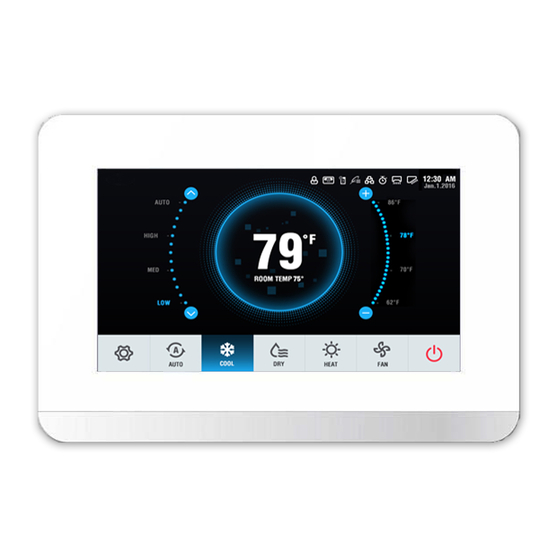
units listed in Table 1. Figure 1 shows a description of the but-
tons used on this controller. Figure 2 shows a description of the
screen icons.
Manufacturer res erves the right to dis continue, or change at any time, s pecifications or des igns without notice and without inc urring obligations .
Ca ta log No. 16-40VM9002-01
Wired Remote Controller (Non-Programmable) Accessory
Part Number 40VM900002
Page
º
º
F to 86
F.
P rinte d in U.S .A.
Form 40VM-1S I
40VM Series Indoor Fan Coils
VRF (Variable Refrigerant Flow) System
Table 1 - Wired Controller Accessory Usage
UNIT
40VMC Compact Cassette Indoor Unit 007, 009, 012, 015
40VMF 4-Way Cassette Indoor Unit
40VMH High Static
40VML Low Static Ducted Indoor Unit 007, 009, 012, 015, 018, 024
40VMM Medium Static Ducted Indoor
Unit
40VMR Floor Console - Recessed
Indoor Unit
40VMU Under Ceiling/Floor Indoor
Unit
40VMV Vertical AHU Fan Coil
40VMW High Wall Indoor Unit
BUTTON
Selects options to the left / Checks the room tempera-
1.
Left button/
ture.
ROOM TEMP
button
Selects the running mode.
2.
MODE
TEMP. UP button Increases the set temperature/Selects upward options.
3.
Powers the IDU (Indoor Unit) on/off.
4.
ON/OFF button
Stays solid green when the unit is powered on and
5.
LED
blinks if there is a fault.
Opens timer settings.
6.
TIMER button
Selects options to the right / Sets the swing location and
7.
Right button/
starts automatic swing.
SWING button
Confirms the selection.
8.
OK button
Reduces the set temperature / Selects downward
9.
TEMP. DOWN
button
options.
Selects the fan speed.
10.
FAN
Fig. 1 - Button Description
P g 1
SIZES
009, 012, 015, 018, 024, 030, 036, 048
024, 030, 036, 048, 054, 072, 096
007, 009, 012, 015, 018, 024, 030, 036,
048
007, 009, 012, 015, 018, 024
012, 018, 024, 030, 036, 048
018, 024, 030, 036, 048, 054
007, 009, 012, 015, 018, 024, 030
DESCRIPTION
12-16
Re pla ce s : Ne w
Advertisement
Table of Contents

Subscribe to Our Youtube Channel
Related Manuals for Carrier 40VM Series


Summary of Contents for Carrier 40VM Series
-
Page 1: Table Of Contents
40VM Series Indoor Fan Coils VRF (Variable Refrigerant Flow) System Wired Remote Controller (Non-Programmable) Accessory Installation and Operating Instructions Part Number 40VM900002 CONTENTS Table 1 — Wired Controller Accessory Usage Page UNIT SIZES SAFETY CONSIDERATIONS ....1 40VMC Compact Cassette Indoor Unit 007, 009, 012, 015 GENERAL . - Page 2 DISPLAY ICON DESCRIPTION Displays the set temperature for cooling on the wired controller. 1. Set Temp for Cooling Displays the IDU (Indoor Unit) address when the IDU is in error or query status. 2. IDU Address Displays the automatic on/off set time. For example, “10H” indicates that the unit will automatically 3.
-
Page 3: Installation Considerations
INSTALLATION CONSIDERATIONS 6. Insert a flat-head screwdriver into the slots provided on the bottom of the controller to pop open the back mount- The thermostat should be mounted: ing plate. See Fig. 3. • approximately 48 in. from the floor •... -
Page 4: Operation
Fan Speed Setting — 10. Mount the controller back onto the mounting plate. See In AUTO, cooling, heating, or Fig. 7. fan-only mode, press FAN to change the fan speed. Pressing FAN changes the setting in the following cycle: automatic air flow, low air flow, medium air flow, high air flow as shown in Fig. -
Page 5: Automatic On/Off Settings
Press the left or right button within 3 seconds to switch be- Press TEMP. UP or TEMP. DOWN within 3 seconds to ad- tween the set temperature for cooling and heating in AUTO just the automatic-on time as shown in Fig. 15. mode as shown in Fig. -
Page 6: Swing Setting For Louvers
NOTE: When the set automatic-on/off time is less than 10 Room Temperature Display — When the unit is on, hours, the value will be increased or decreased in units of press ROOM TEMP. to view the indoor temperature as shown 0.5 hour. -
Page 7: Parameter Settings
lock the ON/OFF, mode setting, and temperature setting func- Parameter settings are classified into 1G code and 2G code. tions, respectively, as shown in Fig. 21. 1G indicates the parameter category, and 2G indicates parame- ter content as shown in Fig. 23. Fig. - Page 8 Press OK or wait 15 seconds to confirm the setting automat- ically and exit parameter settings (see Fig. 26). Table 3 lists the detailed parameter codes. Fig. 26 — Exiting the Parameter Settings Menu Table 3 — Parameter Codes The table below lists the detailed parameter codes: Parameter 1G code 2G code...
- Page 9 0 (default) ∆t=4min Fan off after a delay ∆t=8min of ∆t when the unit is ∆t=12min off (reserved) ∆t=16min Turn off the fan Setting the fan speed in cooling Medium standby mode High E (default) Maintain the current fan speed 0 (default) Turn off the fan Setting the fan...
-
Page 10: Query Function
0 (default) Closed in 15 min Delayed closing setting of dry contact Closed in 30 min Closed in 45 min Whether the IDU is 0 (default) No third-party heat source connected connected to a third-party heat A third-party heat source connected source Fan control when the Not turn on the fan forcedly... -
Page 11: Error Code Display
Press OK to query the IDU at the current address as shown codes of the wired controller. If an error occurs, the LED and in Fig. 30. Operating icon blink as shown in Fig. 32. Fig. 30 — Querying the IDU Press TEMP. - Page 12 © Ca rrie r Corpora tion 2016 Manufacturer res erves the right to dis continue, or change at any time, s pecifications or des igns without notice and without inc urring obligations . Ca ta log No. 16-40VM9002-01 P rinte d in U.S .A. Form 40VM-1S I P g 12 12-16...
Need help?
Do you have a question about the 40VM Series and is the answer not in the manual?
Questions and answers