Avid Technology S6 Installation Manual
For avid s6 m10 and s6 m40 systems
Hide thumbs
Also See for S6:
- Installation manual (92 pages) ,
- Assembling/disassembling (34 pages) ,
- User manual (20 pages)
Table of Contents
Advertisement
Quick Links
Advertisement
Table of Contents

Related Manuals for Avid Technology S6


Summary of Contents for Avid Technology S6
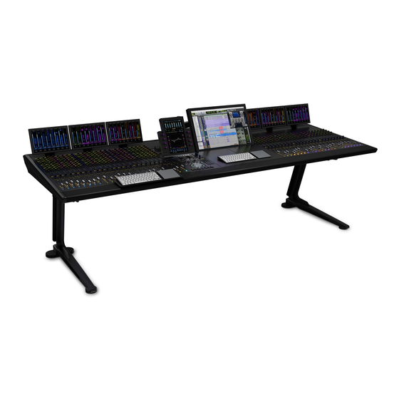
- Page 1 S6 Installation Guide For Avid S6 M10 and S6 M40 Systems...
- Page 2 Legal Notices © 2014 Avid Technology, Inc., ("Avid"), all rights reserved. This guide may not be duplicated in whole or in part without the written consent of Avid. 003, 192 Digital I/O, 192 I/O, 96 I/O, 96i I/O, Adrenaline, AirSpeed, ALEX,...
-
Page 3: Table Of Contents
Contents Part I Introduction Chapter 1. Introduction ................1 . - Page 4 Appendix A. Expanding or Disassembling S6 ........
- Page 5 Part I: Introduction...
-
Page 6: Chapter 1. Introduction
-compatible DAWs (Digital Audio Workstations). S6 is flexible and scalable, letting you choose the best system for your needs. Many different configurations are possible with different numbers of faders, knobs, and displays. All systems let you place the master section in any position, left-to-right, within a frame. -
Page 7: Overview Of Installation
• Registration Card • System Restore USB Flash Drive Do not use the System Restore drive for anything other than S6 System Restore software. Do not use this drive to store audio files or any other data or software. • Health & Safety Guide... -
Page 8: System Requirements And Compatibility
Activate S6 System Software Immediately As soon as you have assembled your S6 system and confirmed a successful hardware installation, activate your S6 system software on-line. Use the alphanumeric code on the included S6 System Software Activation Card to activate and download all S6 system software and documentation. -
Page 9: About This Guide
About This Guide This guide explains how to assemble your Avid S6 system. Conventions Used in This Guide All of our guides use the following conventions to indicate menu choices and key commands: Convention Action File > Save Choose Save from the File menu... -
Page 10: Chapter 2. Modules And Configuration Overview
Chapter 2: Modules and Configuration Overview This chapter identifies each of the S6 modules, and tells you how and where they can be arranged within a system. Use this infor- mation to determine your module layout before proceeding with the assembly. - Page 11 Automation Module Channel Modules Channel modules combine to form the fader strips of the system, and include the S6 Fader Module, S6 Process Module, S6 Knob Module, and S6 Display Module. Not all configurations include each type of channel modules.
- Page 12 Display Module (M40 Systems Only) Display Modules are supported on S6 M40 systems only, and are installed above channel modules. Each Display Module provides a large display that shows names, meters, waveforms, and other data for up to eight strips.
-
Page 13: Module Layout
Module Slot 4 Knob Module Knob Knob Slot 3 Module Module Process Slot 2 Process Module Module Fader Slot 1 Fader Module Module Channel modules in a Frame Chassis Small (left) and a Frame Chassis Large (right) S6 Installation Guide... - Page 14 Left-to-Right Chassis and Module Arrangements Channel sections and the master section modules can be arranged in any order, left-to-right. For example, in an S6 M10–16–5 sys- tem (16 faders with five knobs per strip) the master section modules can be located in three possible locations, as shown below.
- Page 15 S6 Installation Guide...
-
Page 16: Part Ii Frames
Part II: Frames... -
Page 18: Chapter 3. Assembling Legs
Chapter 3: Assembling Legs This chapter explains how to assemble the Leg Frames for the S6. Not all systems require Legs. If your system does not include Leg Frames, please proceed to Chapter 4, “Assembling Frame Chassis.” Make sure you have at least one other person available if you need to lift, turn, or move the system during and after assembly. Com- ponents and systems are heavy! Team lift, always. -
Page 19: Attaching The Back Beam
Make sure the Beam sits flat on the top of the legs as shown in Figure 3. If necessary, move the legs in or out until the proper alignment is achieved. Figure 3. Back view showing correct alignment of Beam on leg (at left), and incorrect alignment (middle, and right) S6 Installation Guide... -
Page 20: Attaching The Front Beam
Attaching the Front Beam To attach the front Beam: Align the pins on the underside of the Beam with the holes in the top of the Legs. Be sure to orient the front Beam so that the pins on the top are closer to the center of the frame. Using four fasteners and washers (included) per mount, attach the Beam across the front of the Legs using two Beam Mounting Plates as shown in Figure 4. -
Page 21: Attaching The Back Corner Brackets
Figure 5. Attaching the Back Corner Brackets Fully tighten all fasteners installed in the previous steps to completely secure the Beams and Back Corner Mounting Brackets to the Legs. Check to make sure the Beams sit flat on the top of the legs. S6 Installation Guide... -
Page 22: Attaching The End Shelves
Attaching the End Shelves To attach the End Shelves: Using four fasteners and washers per side, attach the Left and Right End Shelves to the Legs as shown in Figure 6. Fasteners, Washers, and Tools for End Shelves Fastener M5x15 Washer M4 Hex... -
Page 23: How To Proceed
Use an M4 Hex to adjust the front leveling feet from above. Turn clockwise to raise, counterclockwise to lower. Figure 8. Front leveling foot How to Proceed When your Leg Frames are assembled, proceed to Chapter 4, “Assembling Frame Chassis.” S6 Installation Guide... -
Page 24: Chapter 4. Assembling Frame Chassis
Chapter 4: Assembling Frame Chassis This chapter explains how to assemble the chassis and attach them to each other to form the frame of your S6 system. As recommended in Chapter 1, identify all Frame component kits (Chassis kits, Side Covers, Bolster, and Rear Panel kits) as shown in Figure 9. - Page 25 7 – Fasteners: Phillips and Hex fasteners (not shown) Figure 11. Chassis parts A – Chassis Bottom Plate B – Back Tie Plate C – Side Wall D – Front Tie Plate E – Cable Harnesses (Ethernet/Power) S6 Installation Guide...
-
Page 26: Assembling The Chassis
Attaching the End Side Wall To attach the end Side Wall: Open the S6 Side Covers package and unpack the included Side Wall. Figure 13. End Side Wall Attach the Side Wall to the Chassis Bottom Plate of the right-most chassis using three #1 Phillips screws. The right edge of the Chassis Bottom Plate sits on top of the left edge of the Side Wall as shown in Figure 14. - Page 27 Chassis Bottom Plate. Do not tighten the fasteners yet. Fasteners, Washers, and Tools for Chassis to Beams M6x14 Hex (SHCS) Fasteners Washers Tool M5 Hex (Not to scale) Figure 16. Attaching the first chassis to the Beams of a Leg Frame S6 Installation Guide...
- Page 28 Move the next chassis into position so that the right edge of its Chassis Bottom Plate sits on top of the left edge of the first chassis as shown in Figure 17. Figure 17. Attaching the first two chassis (top view, at left, and front view, at right) If your system includes a Leg Frame, attach the second chassis to the Beams and secure loosely using more of the Hex fasteners included with the Beams as shown in Figure 16.
- Page 29 Important Do not lift or move an S6 desktop system that is five or more chassis in width (32-faders or more). If you need to move a five-or-wider S6 system that does not include Legs, you must partially disassemble the frame so that no section is more than four chassis in width.
-
Page 30: Attaching The Back Feet
Attaching the Back Feet After assembling the chassis, attach the back feet. • One Back Foot is included with each Frame Chassis Kit. • Two Back Foot Mounting Spacer bars and an additional Back Foot are included in the Side Covers kit. Installing Back Foot Mounting Spacers To install the two Back Foot Mounting Spacers: Locate the Back Foot Mounting Spacer bars (2) included in the Side Covers kit. - Page 31 Back Foot, Mounting Bracket, and screws The number of back feet is equal to the number of chassis (width) of the frame, plus one. For example, a 16-fader S6 system has a frame width of three chassis, so it requires four back feet (3+1=4). Similarly, a 32-fader system requires six back feet (5+1=6).
- Page 32 • All other Back Feet are mounted to adjacent Back Tie Plates as shown in Figure 23. Figure 23. Attaching a Back Foot to two adjacent Back Tie Plates Leveling the Chassis After the feet are mounted to the frame, check that the chassis is level. If one or more feet are too short or too tall, raise or lower them in order to level and support the back of the frame.
-
Page 33: Attaching The Bolster
Figure 25. Attaching the Bolster Never attempt to move or lift a chassis (any size) by the Bolster, Side Covers or Rear Panels (they can break). Move or lift while holding on to the metal chassis (frame) instead. S6 Installation Guide... -
Page 34: Installing Display Module Mounting Brackets
If your system includes one or more Display Modules, do the following: Unpack all S6 Display Modules and locate their mounting brackets. Fasteners are included in a small bag taped to the bracket. Use the four flathead Hex fasteners to attach the brackets to the chassis. Set the other four rounded fasteners aside (these will be used to attach the module to the brackets later). -
Page 35: Installing Rear Panel Mounting Brackets
The upper covers have open corners to guide power and Ethernet for Display Modules (if your system includes Display Modules), and cutouts to support S6 Options (such as the Speaker Bridge and VESA Monitor mount). -
Page 36: Installing Side Covers
Installing Side Covers Side Covers (one Left, and one Right) consist of two pieces: a mounting plate that attaches to the frame, and an outer panel that at- taches to the mounting plate and secured from inside the chassis. Attaching the Side Mounting Plates To attach the Side Mounting Plates: Unpack the Side Covers package and identify the Left and Right Side Mounting Plates and their fasteners. -
Page 37: How To Proceed
How to Proceed After assembling the chassis that form your system frame, proceed to Chapter 5, “Installing the Power Strip, PSUs, Switches, and Cables.” S6 Installation Guide... -
Page 38: Part Iii Modules
Part III: Modules... -
Page 40: Chapter 5. Installing The Power Strip, Psus, Switches, And Cables
Chapter 5: Installing the Power Strip, PSUs, Switches, and Cables This chapter explains how and where to install the Power Strip, Ethernet switches and Power Supply Units (PSUs), how to connect Ethernet throughout the system using the included Cable Sets, and how to connect power to PSUs and the switch. As recommended in Chapter 1, identify and organize the packages containing the Power Strip, Ethernet switch(es), PSUs, and Ca- ble Sets. -
Page 41: Installing The Power Strip
Figure 2. Power strip placement on Rear Panel brackets (back view at left, side view at right) Take the power strip’s AC cable and run it along the back of the frame to the far left or right end. Do not connect to power outlet yet. S6 Installation Guide... -
Page 42: Ethernet Switch And Psu Placement Per System Configuration
Ethernet Switch and PSU Placement per System Configuration Figure 3 illustrates switch and PSU placement for an example 32-fader (five chassis wide) system. When determining the placement of the Ethernet switch, observe the following guidelines based on your configuration and frame depth. - Page 43 These diagrams show switch and PSU placement for all frame widths available with Avid-configured S6 systems, which range in size from 8-fader/two chassis (such as an S6 M10-8-5) up to 32-fader/five chassis (such as an M40-32-9-D). For larger (custom) configurations see Chapter 5, “Installing the Power Strip, PSUs, Switches, and Cables”.
- Page 44 Switch and PSU Placement for Custom S6 Configurations These diagrams show switch and PSU placement for example systems that are six or more chassis in width. Install and secure units as shown for your frame size, then proceed to “Installing and Connecting Cabling” on page 44.
-
Page 45: Installing The Ethernet Switch
Do not use the power cable provided in the Ethernet switch box (it has a standard male IEC connector which will not work with the S6 Power Strip). Attach the included feet to the bottom of the Ethernet switch. (Very important!) Refer to the diagrams in “Ethernet Switch and PSU Placement per System Configuration”... -
Page 46: Installing Psus
Installing PSUs Each chassis requires one PSU to supply power for modules. PSUs are installed alone or in pairs and secured with the tie-down brackets (one is included in each Chassis package). To install PSUs: Unpack all PSUs from their packaging, and collect their special AC cables included in the Bolster package. Place one PSU in each chassis but do not place one in the same chassis as the Ethernet switch. - Page 47 • Attach the terminal end to the power terminal connector on the Back Tie Plate of that chassis and secure it with a flathead screwdriver. Figure 14. Routing power cables to a chassis with an Ethernet switch S6 Installation Guide...
- Page 48 Locate the power cables included in each PSU box, as well as those included in the Bolster package. Connect the appropriate end of the power cables from the Bolster package to the PSU (repeat for all PSUs). Feed the other end of the AC cables through the opening in each Back Tie Plate and run them through the upper (square) cable guide openings in the Rear Panel as shown in Figure 15.
-
Page 49: Installing And Connecting Cabling
Cable Sets later, but your specific configuration will determine the best arrangement. Figure 17. Connecting the first Cable Set to the Ethernet switch (top view shown at lower left; back view of chassis shown at upper right) S6 Installation Guide... - Page 50 Run the Cable Set through the (lower) triangular cable guides in the Rear Panel brackets to the furthest (left- or right-most) chas- sis, as shown in Figure 18. (For systems with more than three chassis, see “Installing Cable Sets in Large Configurations” on page 46.) Connect the other ends (1–5) to the Ethernet terminal ports (1–5) on the outside back of the chassis Figure 18.
- Page 51 Cable Set Small Figure 21. Cable Sets in a 24-fader (four chassis) system. 5-Chassis Systems (See Figure 22): Cable Set Large Cable Set Medium Cable Set Small Figure 22. Cable Sets in a 32-fader (five chassis) system S6 Installation Guide...
- Page 52 6-Chassis Systems Systems with 40 faders (six chassis) require slightly different cabling depending on the number of modules in the system (which determines whether the system needs one or two Ethernet switches). Example 1 (Single Ethernet Switch: see Figure 23): Cable Set Large Cable Set Medium Cable Set Small...
- Page 53 Guide the cable across the Rear Panels to the far left-or-right. Do not yet connect it to any workstations, routers, or switches. Do not connect the system to any workstation, external routers, switches or networks until after you have updated S6 system soft- ware as explained later in this guide.
- Page 54 Installing the Tie-Down Bracket for the Ethernet Switch After all Ethernet and power cables are installed, secure the Ethernet switch to its chassis using its included tie-down bracket as shown in Figure 26. The bracket is included in the Ethernet Switch package, and its fasteners are provided in a small plastic bag taped to the bracket.
-
Page 55: Attaching The Outer Side Covers
Make sure power and Ethernet cables are not in the way, then set the panel into the side bracket so that its tabs hang on the slots on the mounting plate as shown in Figure 28. Figure 28. Attaching the left Side Cover S6 Installation Guide... - Page 56 From the inside of the chassis, use four of the included flathead Phillips screws to secure the Side Cover to the frame as shown in Figure 29. Fasteners and Tools for the Side Covers M4x14 FHPH Fasteners #2 Phillips Tool (Not to scale) Figure 29.
-
Page 57: How To Proceed
Never attempt to move or lift a chassis (any size) by the Side Covers, Bolster, or Rear Panels (they can break). Move or lift while holding on to the metal chassis (frame) instead. How to Proceed After assembling the frame and installing the Ethernet switch, PSUs and cabling, proceed to Chapter 6, “Installing Modules.” S6 Installation Guide... -
Page 58: Chapter 6. Installing Modules
• Install a Compression Panel into each chassis to complete the assembly. About These Instructions The following instructions show an S6 M40–24–5 system as an example configuration (see Figure 32). This configuration provides 24 fader strips with 5 knobs per strip, plus a standard master section module configuration. -
Page 59: Installing Modules
Install all modules beginning with the left-most chassis. Begin with the slot/module closest to the front (slot 1). In our example S6 M40 24-5 configuration we are installing channel modules in the left-most chassis, so the first (front-most) module to install is a Fader Module. - Page 60 Locate the Process Module and connect power and Ethernet to it as you did for the Fader Module. Use the longest available power and Ethernet cables in that Cable Harness. Install the connected Process Module in slot 2 behind the Fader Module, being careful to orient it correctly and seat it fully against the top edge of the Fader Module.
- Page 61 Example of a Frame Chassis Large with one Fader Module, one Process Module and two Knob Modules Repeat steps 1–7 for all other Channel modules. Slot 3 Knob Module Slot 2 Process Module Slot 1 Fader Module Channel Modules installed (switch and PSUs not shown) S6 Installation Guide...
- Page 62 Installing Master Section Modules Installing the Automation Module is nearly identical to installing a Fader Module. Installing the Automation Module To install the Automation Modules: If you haven’t already done so, unpack the Automation Module and Master Module. Hold the Automation module above its chassis and do the following: •...
- Page 63 Figure 33. Connecting both DC power cables to the Master Module Connect the longest available Ethernet cable to the Ethernet port on the side of the module (see Figure 34): Gigabit Ethernet RJ45 Figure 34. Master Module side panel Ethernet port S6 Installation Guide...
- Page 64 (left) on the back panel of the Master Module. • If you are not connecting S6 to an existing DHCP Server on your network (and/or if you will be connecting S6 directly to only one workstation) connect the second chassis Ethernet cable to back panel Ethernet port (right).
-
Page 65: Installing Fill Panels
There are two positions to mount the Display Module, low and high. Select a position, then attach the Display Module to a Dis- play Module Mounting Bracket and secure it with the included mounting screws. Fasteners, and Tools for Display Module Fasteners M4x10 BCHS Tool M2.5 Hex Attaching a Display Module to its mounting bracket (side view) S6 Installation Guide... - Page 66 Do not connect anything to the USB ports unless directly instructed to do so by an Avid Authorized Service provider. Repeat the previous steps to install other Display Modules. After all Display Modules are in place, go to Chapter 7, “How to Proceed” to complete the installation of your S6 system. Chapter 6: Installing Modules 61...
- Page 67 S6 Installation Guide...
-
Page 68: Chapter 7. How To Proceed
Activate and Register Before continuing, review the Activation Card and Registration Information Card (included in the pouch at the front of this S6 In- stallation Guide binder). Use a separate computer and follow the instructions to activate your Avid Master Account (required) and register your purchase (optional, but highly recommended). -
Page 69: Complete The Hardware Assembly
Compression Panel into place at the top of the chassis as shown in Figure 37. Figure 37. Installing a Channel Compression Panel Repeat for other Channel chassis. S6 Installation Guide... - Page 70 Take the Master Compression Panel (included in the Side Covers package) and hold it so that the side with the springs faces the back of the frame. If you have a Frame Chassis Small, use the smaller Master Compression Panel. Holding the panel at an angle, place the spring side of the panel against the back of the chassis.
- Page 71 • If your system does not include Display Modules, close the Rear Panel upper covers and then install Display Module Fillers (shown in Figure 42) to seal the openings at the corners of adjacent covers. One Filler is included with each chassis. Figure 42. Display Module Filler S6 Installation Guide...
-
Page 72: Updating S6 System Software
Plug the USB flash drive with the downloaded S6 Master Module installer into one of the available USB ports on the back of the Master Module. The USB drive will now show up in the left hand column under Computer Tap on the USB flash drive to see the contents. -
Page 73: Configuring The S6 System
My Products S6 Software Updates You can download these components directly to the workstation(s) you plan to use with S6, or to a USB flash drive as described in the following steps. Transfer the installers to a USB flash drive. -
Page 74: Part Iv Appendices
Part IV: Appendices... -
Page 76: Appendix A. Expanding Or Disassembling S6
Important Do not attempt to lift or move an assembled S6 desktop system if it is five or more chassis in width to avoid risk of damage to the frame. If you need to move a five chassis-or-wider S6 system that does not include Legs, you must partially disassemble the frame so that no section is more than four chassis in width. -
Page 77: Disassembling A Frame
• If you expanding a frame, detach any two interior chassis and install the new chassis between them. When expanding an S6 frame always insert new chassis between existing chassis (do not add a new chassis at either the extreme left or right ends, unless you are adding a Producer’s Desk to either end). -
Page 78: Appendix B. Compliance
Appendix B: Compliance Environmental Compliance Disposal of Waste Equipment by Users in the European Union This symbol on the product or its packaging indicates that this product must not be disposed of with other waste. Instead, it is your responsibility to dispose of your waste equipment by handing it over to a designated collection point for the recycling of waste elec- trical and electronic equipment. -
Page 79: Emc (Electromagnetic Compliance)
Cet appareil numérique de la classe B respecte toutes les exigences du Règlement sur le material brouilleur du Canada. CE Compliance (EMC and Safety) Avid is authorized to apply the CE (Conformité Europénne) mark on this compliant equipment thereby declaring conformity to EMC Directive 2004/108/EC and Low Voltage Directive 2006/95/EC. S6 Installation Guide... -
Page 80: Safety Compliance
Standards: UL 60065 7th Ed., 2007-12-11, CAN/CSA C22.2 No. 60065-03, 1st Ed, 2006-04 +A1:2006, EN 60065:2002 + A1:2006 + A11:2008, IEC 60065:2001 + A1:2005 + A2:2010. Avid Technology Inc., has been authorized to apply the appropriate NRTL mark on its compliant equipment. Korea Class B EMC Compliance 이... - Page 81 CAUTION: For continued protection against risk of fire, replace only with same type and rating of fuse. ATTENTION: Pour ne pas compromettre la protection contre les risques d’incendie, remplacer par un fusible de même type et de même caractéristiques nominales. S6 Installation Guide...
- Page 82 Avid Technical Support (USA) Product Information 2001 Junipero Serra Boulevard Visit the Online Support Center at For company and product information, Daly City, CA 94014-3886 USA www.avid.com/support visit us on the web at www.avid.com...
Need help?
Do you have a question about the S6 and is the answer not in the manual?
Questions and answers