Table of Contents
Advertisement
www.proform.com
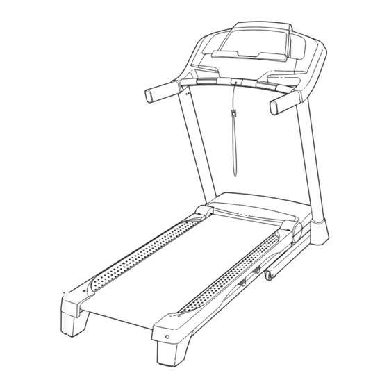
Model No. PFTL59510.0
Serial No.
Write the serial number in the space
above for reference.
Serial Number
Decal
QUESTIONS?
If you have questions, or if parts
are damaged or missing, DO NOT
CONTACT THE STORE; please
contact Customer Care.
IMPORTANT: Please register this
product (see the limited warranty
on the back cover of this manual)
before contacting Customer Care.
CALL TOLL-FREE:
1-888-533-1333
Mon.–Fri. 6 a.m.–6 p.m. MT
Sat. 8 a.m.–4 p.m. MT
ON THE WEB:
www.proformservice.com
CAUTION
Read all precautions and instruc-
tions in this manual before using
this equipment. Save this manual
for future reference.
USER'S MANUAL
Advertisement
Table of Contents

Related Manuals for Pro-Form PFTL59510.0


Summary of Contents for Pro-Form PFTL59510.0
- Page 1 USER’S MANUAL Model No. PFTL59510.0 Serial No. Write the serial number in the space above for reference. Serial Number Decal QUESTIONS? If you have questions, or if parts are damaged or missing, DO NOT CONTACT THE STORE; please contact Customer Care.
-
Page 2: Table Of Contents
TABLE OF CONTENTS WARNING DECAL PLACEMENT ............. . .2 IMPORTANT PRECAUTIONS . -
Page 3: Important Precautions
IMPORTANT PRECAUTIONS WARNING: To reduce the risk of serious injury, read all important precautions and instructions in this manual and all warnings on your treadmill before using your treadmill. ICON assumes no responsibility for personal injury or property damage sustained by or through the use of this product. - Page 4 DANGER: 20. Never leave the treadmill unattended while it Always unplug the power is running. Always remove the key, unplug cord immediately after use, before clean- the power cord, and press the power switch ing the treadmill, and before performing the into the off position when the treadmill is not maintenance and adjustment procedures in use.
-
Page 5: Before You Begin
BEFORE YOU BEGIN Thank you for selecting the revolutionary PROFORM reading this manual, please see the front cover of this ® PERFORMANCE 400 treadmill. The PERFORMANCE manual. To help us assist you, please note the product 400 treadmill offers an impressive selection of features model number and serial number before contacting us. -
Page 6: Assembly
ASSEMBLY To hire an authorized service technician to assemble the treadmill, call 1-800-445-2480. Assembly requires two persons. Set the treadmill in a cleared area and remove all packing materials. Do not dispose of the packing materials until assembly is completed. Note: The underside of the treadmill walking belt is coated with high-performance lubricant. -
Page 7: Fully Fold The Frame Yet
1. Make sure that the power cord is unplugged. Hole With the help of a second person, carefully tip the treadmill onto its left side. Partially fold the Frame (55) so that the treadmill is more stable; do not fully fold the Frame yet. Cut the shipping tie securing the Upright Wire (87) to the Base (95). - Page 8 3. Identify the Right Upright (85), which is marked with a "Right" sticker. Hold the Right Upright near the Base (95) as shown. See the inset drawing. Tie the wire tie in the Right Upright (85) securely around the end of Wire Tie the Upright Wire (87).
-
Page 9: Fully Fold The Frame Yet
5. With the help of a second person, carefully tip the treadmill onto its right side. Partially fold the Frame (55) so that the treadmill is more stable; do not fully fold the Frame yet. Attach a Wheel (96) to the Base (95) with a 3/8" x 2"... - Page 10 7. Identify the Right Base Cover (91) and the Left Base Cover (88). Slide the Right Base Cover onto the Right Upright (85). Slide the Left Base Cover onto the Left Upright (84). 8. Remove the tie from the bracket on the Right Handrail (83).
- Page 11 9. Set the console assembly face down on a soft surface to avoid scratching the console assem- bly. Remove the two #8 x 3/4" Screws (1). Next, lift off the Crossbar (107). Console Assembly 10. IMPORTANT: To avoid damaging the Crossbar (107), do not use power tools and do not overtighten the #10 x 3/4"...
- Page 12 11. With the help of a second person, hold the con- sole assembly near the Right Handrail (83). Console Console Assembly Wire Connect the Upright Wire (87) to the console wire. See the inset drawing. The connectors should slide together easily and snap into place.
- Page 13 13. Raise the Frame (55) to the position shown. Have a second person hold the Frame until this step is completed. Orient the Storage Latch (51) so that the large barrel and the latch knob are oriented as shown. Attach the Latch Bracket (6) and Storage Latch (51) to the Base (95) with two 3/8"...
-
Page 14: Operation And Adjustment
OPERATION AND ADJUSTMENT HOW TO CONNECT THE POWER CORD nominal 120-volt circuit capable of carrying 15 or more amps. To avoid overloading the circuit, do Use a Surge Suppressor not plug other electrical devices, except for low- power devices such as cell phone chargers, into Your treadmill, like other electronic equipment, can be the surge suppressor or into an outlet on the same circuit. - Page 15 CONSOLE DIAGRAM FEATURES OF THE CONSOLE monitor your progress toward your fitness goals. To purchase a SYNC at any time, call the telephone number on the front cover of this manual. The treadmill console offers an impressive array of features designed to make your workouts more effec- tive and enjoyable.
- Page 16 HOW TO TURN ON THE POWER HOW TO USE THE MANUAL MODE IMPORTANT: If the treadmill has been exposed to 1. Insert the key into the console. cold temperatures, allow it to warm to room tem- perature before you turn on the power. If you do See HOW TO TURN ON THE POWER at the left.
- Page 17 4. Change the incline of the treadmill as desired. The Distance/Speed display—This display To change the incline of the treadmill, press the can show the distance Incline increase or decrease button or one of the that you have walked incline buttons numbered 0 through 10. Each time or run.
- Page 18 6. Measure your heart rate if desired. 7. When you are finished exercising, remove the key from the console. Before using the hand- Step onto the foot rails, press the Stop button, and adjust the incline of the treadmill to the lowest grip heart rate monitor, setting.
- Page 19 HOW TO USE AN ONBOARD WORKOUT the displays for a few seconds and the treadmill will automatically adjust to the new speed and/or 1. Insert the key into the console. incline setting. See HOW TO TURN ON THE POWER on page 16. The workout will continue in this way until the last segment of the profile flashes in the display and the 2.
- Page 20 HOW TO USE AN IFIT LIVE WORKOUT www.iFit.com. Note: If there are no workouts of the selected type in your queue, the next workout 1. Insert the key into the console. in your queue will be downloaded. See HOW TO TURN ON THE POWER on page 16. When you select an iFit Live workout, the displays will show the duration of the workout, the distance 2.
- Page 21 HOW TO USE A PROFORM SYNC To use the SYNC, you must have an iPod nano (4th ® or 5th generation) or an iPod touch (2nd, 3rd, or 4th ® The optional PROFORM SYNC enables you to generation). You must also have access to a computer record your treadmill workout results on your iPod with an internet connection.
- Page 22 THE INFORMATION MODE If a module is connected, the information mode will also show the following screens: The console features an information mode that keeps track of treadmill information and allows you to person- If an iFit Live module, a USB module, or a PROFORM alize console settings.
- Page 23 HOW TO USE THE STEREO SOUND SYSTEM To use the SYNC, plug a compatible iPod (not included) into the cable extending from the SYNC. This treadmill has been designed specifically to work Make sure that the iPod is fully plugged in. with iPod and has been certified by the developer to meet Apple performance standards.
-
Page 24: How To Fold And Move The Treadmill
HOW TO FOLD AND MOVE THE TREADMILL HOW TO FOLD THE TREADMILL HOW TO MOVE THE TREADMILL To avoid damaging the treadmill, adjust the incline Before moving the treadmill, fold it as described at the to the lowest position before you fold the treadmill. left. -
Page 25: Troubleshooting
TROUBLESHOOTING Most treadmill problems can be solved by following the simple steps below. Find the symptom that applies, and follow the steps listed. If further assistance is needed, see the front cover of this manual. PROBLEM: The power does not turn on SOLUTION: a. - Page 26 Remove the three #8 x 3/4" Screws (1) and care- fully pivot the Motor Hood (62) off. Locate the Reed Switch (73) and the Magnet (47) on the left side of the Pulley (48). Turn the Pulley until the Magnet is aligned with the Reed Switch. Make sure that the gap between the Magnet 1/8 in.
- Page 27 PROBLEM: The walking belt is off-center or slips when walked on SOLUTION: a. If the walking belt is off-center, first remove the key and UNPLUG THE POWER CORD. If the walking belt has shifted to the left, use the hex key to turn the left idler roller bolt clockwise 1/2 of a turn;...
-
Page 28: Exercise Guidelines
EXERCISE GUIDELINES Burning Fat—To burn fat effectively, you must exer- WARNING: cise at a low intensity level for a sustained period of Before beginning this time. During the first few minutes of exercise, your or any exercise program, consult your physi- body uses carbohydrate calories for energy. - Page 29 SUGGESTED STRETCHES The correct form for several basic stretches is shown at the right. Move slowly as you stretch —never bounce. 1. Toe Touch Stretch Stand with your knees bent slightly and slowly bend forward from your hips. Allow your back and shoulders to relax as you reach down toward your toes as far as possible.
-
Page 30: Part List
PART LIST Model No. PFTL59510.0 R0212B Key No. Qty. Description Key No. Qty. Description #8 x 3/4" Screw Storage Latch #10 x 3/4" Screw Console Ground Wire Inner Cushion #8 x 1" Screw 5/16" x 1" Bolt Right Foot Rail #8 x 1"... - Page 31 Key No. Qty. Description Key No. Qty. Description Console Console Base Console Frame Crossbar Left Tray Right Tray #8 x 3/4" Truss Head Screw – User’s Manual Console Clamp Note: Specifications are subject to change without notice. For information about ordering replacement parts, see the back cover of this manual.
-
Page 32: Exploded Drawing
EXPLODED DRAWING A Model No. PFTL59510.0 R0212B... - Page 33 EXPLODED DRAWING B Model No. PFTL59510.0 R0212B...
- Page 34 EXPLODED DRAWING C Model No. PFTL59510.0 R0212B...
- Page 35 EXPLODED DRAWING D Model No. PFTL59510.0 R0212B...
-
Page 36: Ordering Replacement Parts
ORDERING REPLACEMENT PARTS To order replacement parts, please see the front cover of this manual. To help us assist you, be prepared to pro- vide the following information when contacting us: • the model number and serial number of the product (see the front cover of this manual) •...
Need help?
Do you have a question about the PFTL59510.0 and is the answer not in the manual?
Questions and answers