Advertisement
MANUALE D'USO E INSTALLAZIONE
USE AND INSTALLATION MANUAL
MANUEL D'UTILISATION ET D'INSTALLATION
B E D I E N U N G S - U N D
I N S T A L L A T I O N S A N L E I T U N G
MANUAL DE INSTRUCCIONES E INSTALACIÓN
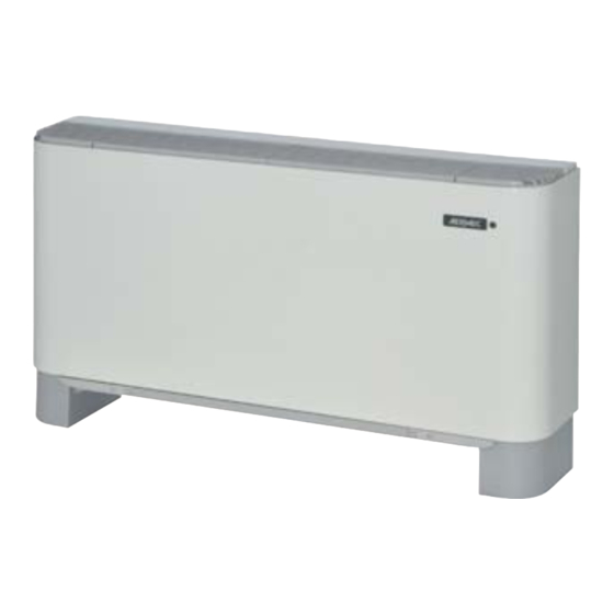
FCXI
AS_U
230V ~ 50Hz
IT
EN
FR
DE
ES
pag.6
pag.20
pag.34
pag.48
pag.62
IFCXIIJ 1501 - 5386400_00
Advertisement

Summary of Contents for AERMEC FCXI Series
- Page 1 MANUALE D’USO E INSTALLAZIONE USE AND INSTALLATION MANUAL MANUEL D'UTILISATION ET D'INSTALLATION B E D I E N U N G S - U N D I N S T A L L A T I O N S A N L E I T U N G MANUAL DE INSTRUCCIONES E INSTALACIÓN FCXI AS_U...
- Page 2 TRASPORTO • TRANSPORT • TRANSPORT • TRANSPORT • TRANSPORTE FCXI_AS_U_P >25Kg IMBALLO IFCXIIJ 1409 - 5386400_00...
-
Page 3: Table Of Contents
FCXI_AS_U IT - INDICE Index General warnings ....................................21 .................................... 22 ......................................22 Maintenance ......................................24 ..................................25 Main components ....................................25 ................................... 25 ............................26 ..................................... 27 Versions and sizes available .................................. 27 ......................................28 ................................... 30 Condensate drain ....................................31 Electrical wiring ..................................... -
Page 4: General Warnings
ATTENTION! DANGER! Any use maintenance and/or repairs. plate supply is used. accessories must only be performed out. Aermec will not be liable for dama- ATTENTION: maged during transport before instal- dangerous; environment. ATTENTION: Note: future reference and for any commu-... - Page 5 • • not undergo violent impacts in or- • • vided. Aermec accessories are supplied com- Indicate any damage or missing com- nents; • and use. HANDLING Aermec accessories are designed to ATTENTION! Wear proper personal protective...
- Page 6 FCXI_AS_U Before installation, check the techni- own, as it may be very dangerous! cal spaces required : and invalids. Prevent temperature fluctuations between indoors and for installation; After-sales Service immediately. • DO NOT PULL THE ELECTRIC • summer. cuits and to any valve; CABLE Excessively low temperatures during •...
-
Page 7: Maintenance
FCXI_AS_U 26. MAINTENANCE ATTENTION: ATTENTION: CAUTION: ATTENTION: ROUTINE MAINTENANCE • Routine maintenance can be performed even at maximum efficiency. • efficient operation. maintenance intervention; every anomaly must solvents. • Do not spray water on internal or external Clean often and use a suction device to remove accumulated dust. -
Page 8: Main Components
FCXI_AS_U 27. DESCRIPTION OF THE UNIT FCXI series units are fan coil terminals to treat system can FCXI accurately. FCXI FCXI accessories supplied. VMF system gives you control energy saving. 28. MAIN COMPONENTS Example: FCXI 40 U 1 Control panel (accessory) - Page 9 FCXI_AS_U ELECTRIC CONNECTIONS louver opening control. Closed louvers disable 30. EXAMPLES OF SYSTEM CONFIGURATIONS WITH FCXI Key: SW Water temperature probe SA Room temperature probe PC Plasmacluster 4-pipe system with standard coil and VCF_X4 valve FANCOIL FANCOIL VCF_X4 VCF_X4 2-pipe system with water probe 2-pipe system without water probe 4-pipe system with water probe 4-pipe system without water probe...
-
Page 10: Versions And Sizes Available
FCXI_AS_U 31. OPERATING LIMITS FCXI 20-24 30-34-36 40-44 50-54-56 80-84 Maximum water inlet temperature Maximum operating pressure 8 bar Environment temperature limits (Ta) Electric power supply 230V ( ~ 50Hz Water temperature Minimum average water temperature off for a prolonged period and cold water flows in therefore, we recommend installing the 3-way valve (accessory). - Page 11 FCXI_AS_U OPERATING ENVIRONMENT WARNINGS FOR THE QUALITY OF THE WATER CIRCULATING IN THE COILS = 0 mg/litre Dissolved iron Dissolved oxygen and irreparable damage from corrosion. 33. INSTALLATION INFORMATION FOR INSTALLATION ATTENTION: Ensure that the power ATTENTION: keep electric attachments separate systems as well as for inspecting them to ensu- supply has been disconnected before from the hydraulic attachments.
- Page 12 FCXI_AS_U logic preferred. • 3 speeds. • motor. front guards. grams. ATTENTION: PREPARATION FOR INSTALLATION • Preparation of the fan coil ATTENTION: some accessories may not be ATTENTION:some versions include an electri- (Example 1) 65 mm FCXI80U-84U FCXI20U-56U FCXI_AS • Selection of the installation position installation.
- Page 13 FCXI_AS_U 34. HYDRAULIC CONNECTIONS ATTENTION: nections. • seals. To avoid drips during the cooling operation, it is pipework with a spanner. Standard coil attachments (female) FCXI 30 - 36 50 - 56 1 / 2 ” 1 / 2 ” 3 / 4 ”...
-
Page 14: Condensate Drain
FCXI_AS_U 35. CONDENSATE DRAIN condensate drain fitting supplied. Care must between tray and fitting. condensate drainage system by pouring water 36. ELECTRICAL WIRING We recommend using differential devices suita- ble for intervening for currents of different type: components supplied as accessories; ensure sinusoidal AC and pulsating DC currents suddenly applied or slowly rising. -
Page 15: Alarm Codes
FCXI_AS_U 37. ALARM CODES FCXI20 FCXI24 FCXI30 FCXI34 FCXI80 only. FCXI40 FCXI44 FCXI84 FCXI50 FCXI54 dismantling. LEDS DANGER! Alarm Power access it. messages. ALARM TYPE INDICATIONS IRREGULARITY Notes Auto-Restart Alarm. Overvoltage Motor off Undervoltage 1.5min Overcurrent Overload Power limitation Speed reduction Safety control Temperature limitation STOP... - Page 16 FCXI_AS_U 38. ROTATING THE COIL 180° proceed as follows: side; viously removed screws; screws; COMPLETING THE INSTALLATION • Completing the installation • Controls ≤ 3mm 39. PROBLEMS AND SOLUTIONS PROBLEM PROBABLE CAUSE REMEDY Wrong setting on control panel. See control panel settings. It does not cool.


Need help?
Do you have a question about the FCXI Series and is the answer not in the manual?
Questions and answers