Advertisement
Quick Links
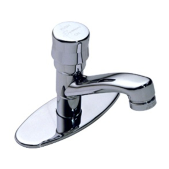
Metering Faucet
S-71, S-72, S-73, S-74 Series
INSTALLATION, OPERATION AND SERVICE INSTRUCTIONS
IMPORTANT:
• Water lines MUST be thoroughly flushed BEFORE and
AFTER installing the faucet to prevent foreign matter,
i.e. copper chips, sand, stones, etc. from clogging and
possibly damaging the sealing surface of the cartridge.
• Integral supply check included (S-73 and S-74 series only).
INSTALLATION:
(Supply stop valves must have a 3/8" O.D. compression outlet.)
1. Apply a bead of sealant to the underside of the faucet
escutcheon.
2. (S-72 and S-74 series): Install U-channel spacers (KN-23),
spacers (KN-26) and nuts (L-36) loosely on mounting bolts.
Position deck plate (SPF-28) and mounting gasket (SPF-27)
under base through sink with flat in center hole towards
the back of sink basin. Secure by tightening nuts from
underside. Insert faucet supply through deck plate aligning
flat on faucet body above threaded shank with flat in deck
plate center hole. Secure faucet to deck plate by placing the
washer (K-60), locknut (SPF-38) and hex nut (SPF-26) on the
supply shank. Hand tighten only! Adjust position of faucet
to achieve optimum spray into basin. Tighten faucet securely
to basin or deck plate.
(S-71 and S-73 series): Insert faucet with flange (SPF-5)
through hole in basin. Secure faucet to basin by placing the
washer (K-60), locknut (SPF-38) and hex nut (SPF-26) on the
supply shank. Hand tighten only! Adjust position of faucet
to achieve optimum spray into basin. Tighten faucet securely
to basin.
3. Connect 4-10C mixing valve to bottom of supply shank using
supply nut provided (S-73 and S-74 series only). Make
connection to water supplies using the appropriate connectors.
4. Install grid drain (if applicable) by removing flange and tube
from drain body and inserting tail piece into trap. Apply
bead of sealant to underside of flange and insert flange and
tube through drain opening. Place bottom gasket mounting
washer and mounting nut onto flange and tube assembly.
Screw drain body on tube until tight.
5. To flush faucet, remove spray outlet, using vandal proof
wrench (LL-60K) provided with faucet. Open cold supply and
depress handle holding down for ten seconds (S-71 and
S-72 series only). Open hot supply and repeat above pro-
cedure (S-73 and S-74 series only). Allow faucet to shut
off and replace spray outlet.
Temperature adjustment
Make sure the faucet has been properly installed and thor-
oughly flushed. Set the mixing valve (4-10C) to the desired
maximum temperature by inserting a 1/4" hex socket key
into the mating hex socket in center of valve and turning
counter clockwise for hotter, clockwise for colder. 110ºF
recommended unless otherwise specified.
(S-73 and S-74 series only)
S-71/S-73
3
4 "
8
1
6 "
2
7
"
min.
8
deck hole
optional 3 hole deck plate
spacer
1
"-20
UNC
4
Adjustment of cycle time
After faucet has been operated through a number of cycles
and supply water temperature is at designed level, adjust-
ment of this feature can be made as follows.
Loosen set screw (LL-27) in cap (SPF-104), remove cap. To
increase time, remove one or more of the washers (LL-28) on
stem. To reduce time, add washers. When desired time cycle
is achieved replace cap and tighten set screw.
S-72/S-74
15˚
7
2 "
8
1
1 "
8
max.
1
2 "
8
1
"-14
NPSM
2
4"
2"
1
2 " with optional 3 hole deck plate
2
6"
1
"
2
with spacer
1
1 "
8
without spacer
4"
Advertisement

Related Manuals for Symmons S-72 Series


Summary of Contents for Symmons S-72 Series
- Page 1 Adjustment of cycle time depress handle holding down for ten seconds (S-71 and S-72 series only). Open hot supply and repeat above pro- After faucet has been operated through a number of cycles cedure (S-73 and S-74 series only). Allow faucet to shut and supply water temperature is at designed level, adjust- off and replace spray outlet.
- Page 2 S-71 and S-73 Series K-60 Washer L-42 Coupling nut LL-1 Control spindle 3/32" HEX SOCKET KEY LL-3N LL-1A Control cartridge LL-1B Control cartridge for quick-closing LL-48 LL-2A Cycle spindle assembly SPF-104 LL-3N Upper housing LL-27 LL-4 Piston washer screw LL-35 LL-8 Cycle spindle guide LL-28...
- Page 3 S-72 and S-74 Series K-60 Washer L-42 Coupling nut LL-1 Control spindle 3/32" HEX SOCKET KEY LL-3N LL-1A Control cartridge LL-1B Control cartridge for quick-closing LL-48 LL-2A Cycle spindle assembly SPF-104 LL-3N Upper housing LL-27 LL-4 Piston washer screw LL-35 LL-8 Cycle spindle guide LL-28...
- Page 4 02184-3804 or call our Customer Service Department at 1-800-SYMMONS. If writing to us, Damage to the chrome and/or other decorative finishes on Symmons products may be a result please include proof of purchase, the model number of the product with a brief description of improper handling or abusive treatment.
Need help?
Do you have a question about the S-72 Series and is the answer not in the manual?
Questions and answers