H3C WA2610E-AGN Installation Manual
Wlan wa2600 series
Hide thumbs
Also See for WA2610E-AGN:
- Web-based configuration manual (447 pages) ,
- Fundamentals configuration manual (137 pages) ,
- Command reference manual (131 pages)
Table of Contents
Advertisement
Quick Links
Download this manual
See also:
Configuration Manual
Advertisement
Table of Contents

Related Manuals for H3C WA2610E-AGN


Summary of Contents for H3C WA2610E-AGN
- Page 1 H3C WA2600 Series WLAN Access Points Installation Manual Hangzhou H3C Technologies Co., Ltd. http://www.h3c.com Manual Version: 5PW100-20081111...
- Page 2 Copyright © 2008, Hangzhou H3C Technologies Co., Ltd. and its licensors All Rights Reserved No part of this manual may be reproduced or transmitted in any form or by any means without prior written consent of Hangzhou H3C Technologies Co., Ltd. Trademarks H3C,...
-
Page 3: About This Manual
About This Manual Organization H3C WA2600 Series WLAN Access Points Installation Manual is organized as follows: Chapter Contents Introduces the hardware configurations, 1 Product Overview appearance, and interfaces of the H3C WA2600 Series WLAN Access Points. Specifies the environmental requirements... -
Page 4: Obtaining Documentation
Description Means a complementary description. Obtaining Documentation You can access the most up-to-date H3C product documentation on the World Wide Web at this URL: http://www.h3c.com. The following are the columns from which you can obtain different categories of product documentation: [Products &... -
Page 5: Table Of Contents
Table of Contents 1 Product Overview .................1-1 Introduction..................1-1 Hardware Configuration ..............1-2 LEDs ...................1-3 Interfaces ..................1-5 2 Preparing for Installation ..............2-1 Unpacking and Inspection..............2-1 Preparing Installation Tools..............2-2 Examining the Installation Site ............2-3 Installation Site Selection ............2-3 Temperature and Humidity Requirements .........2-3 Power Supply................2-4 Grounding and Lightning Protection ...........2-5 3 Installing the AP..................3-1... - Page 6 List of Figures Figure 1-1 Typical networking using the WA2600 series ....1-1 Figure 1-2 Appearance of the WA2600 series ........1-2 Figure 1-3 LEDs on the H3C WA2610E-AGN........1-3 Figure 1-4 LEDs on the H3C WA2620E-AGN........1-3 Figure 1-5 Interfaces on the H3C WA2610E-AGN......1-6 Figure 1-6 Interfaces on the H3C WA2620E-AGN......1-7...
- Page 7 List of Tables Table 1-1 Physical dimensions and weight of the WA2600 series ..1-2 Table 1-2 Supported protocols and chassis material......1-2 Table 1-3 Description of the LEDs on the WA2610E-AGN and WA2620E-AGN................1-4 Table 1-4 Descriptions of interfaces on the WA2600 series WLAN access points ................1-8...
-
Page 8: Product Overview
WA2600 series) are one of the 802.11n access point (AP) product series developed by Hangzhou H3C Technologies Co., Ltd. (hereinafter referred to as H3C). The WA2600 series can serve as FIT APs to cooperate with wireless local area network (WLAN) switches or access controllers to provide wireless access for WLAN users. -
Page 9: Hardware Configuration
The two models of the WA2600 series have different radio frequencies (RFs) and structures. Table 1-2 lists the supported protocols and the chassis material. Table 1-2 Supported protocols and chassis material Model Protocols and chassis material IEEE 802.11a/b/g/n, single-RF, sheet H3C WA2610E-AGN metal... -
Page 10: Leds
LEDs The positions and identifications of LEDs on the panel vary with the models. For details about these LEDs, see Table 1-3. H3C WA2610E-AGN Figure 1-3 LEDs on the H3C WA2610E-AGN H3C WA2620E-AGN Figure 1-4 LEDs on the H3C WA2620E-AGN... -
Page 11: Table 1-3 Description Of The Leds On The Wa2610E-Agn And Wa2620E-Agn
Table 1-3 Description of the LEDs on the WA2610E-AGN and WA2620E-AGN Color Meaning Displays the power supply status: On: The power supply is normal. POWER Green Off/blinking: The power supply is not well connected or works abnormally. Displays the wireless link status: On: The wireless link is normal. -
Page 12: Interfaces
Color Meaning Displays the status of the Ethernet interface: On: The Ethernet interface is in 10/100M the link-up state. (Ethernet Yellow Off: The Ethernet interface is in interface the link-down state. LED) Blinking: Data being transmitted received 10/100 Mbps. Displays the status of the 1000 M Ethernet interface: On: The Ethernet interface is in 1000M... -
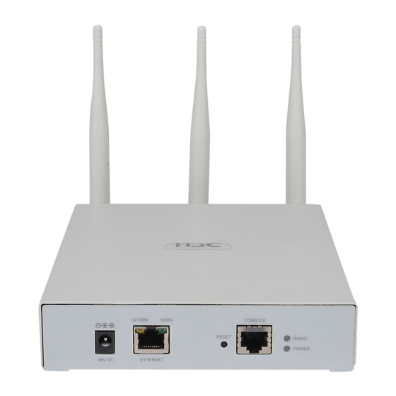
Page 13: Figure 1-5 Interfaces On The H3C Wa2610E-Agn
In addition, the WA2600 series have a reset button and a security slot. Interfaces provided by the H3C WA2610E-AGN Figure 1-5 Interfaces on the H3C WA2610E-AGN... -
Page 14: Figure 1-6 Interfaces On The H3C Wa2620E-Agn
Interfaces provided by the H3C WA2620E-AGN Figure 1-6 Interfaces on the H3C WA2620E-AGN Table 1-4 describes the interfaces provided by each model. -
Page 15: Table 1-4 Descriptions Of Interfaces On The Wa2600 Series Wlan
Table 1-4 Descriptions of interfaces on the WA2600 series WLAN access points Standards Model Interface Description protocols IEEE802.11 The antenna interfaces IEEE802.11 ANT-1 are provided for 2.4 ANT-2 GHz/5 GHz dual-RF IEEE802.11 antennas for MIMO ANT-3 transmission. IEEE802.11 The console interface is used for device Console RS/EIA-232... - Page 16 Standards Model Interface Description protocols IEEE802.11 Antenna This antenna interface is IEEE802.11 interface used to connect a 2.4 (2.4 G) GHz antenna or a feeder. IEEE802.11 IEEE802.11 Antenna This antenna interface is interface used to connect a 5 GHz IEEE802.11 (5 G) antenna or a feeder.
-
Page 17: Preparing For Installation
WA2600 WLAN AP 1 PCS Power adapter 1 PCS 220 VAC power cord 1 PCS Console cable 1 PCS Installation kit 1 set Omni antennas 3/6 PCS H3C WA2600 Series WLAN Access Points 1 PCS Installation Manual Packing list 1 PCS... -
Page 18: Preparing Installation Tools
If the package is found to be rusted or water soaked, stop unpacking and contact your local dealer immediately. Three omni antennas are shipped with the WA2610E-AGN, while six omni antennas are shipped with the WA2620E-AGN. Preparing Installation Tools When installing the AP, you may need the tools listed in Table 2-2. -
Page 19: Examining The Installation Site
Table 2-2 is for reference only. If you install the AP on a tabletop, none of the above tools is required. Examining the Installation Site Before installation, examine the installation site to make sure that the AP will work in a good environment. You can examine the installation site from the following two aspects. -
Page 20: Power Supply
Specification Range –40°C to +70°C (–40°F to Storage temperature +158°F) Relative humidity 10% to 95% (noncondensing) Power Supply Check that the power supply of the installation site is stable. The centralized AC power system consisting of the AC mains, UPS, and user-supplied diesel generator should be: Easy to connect Safe to operate... -
Page 21: Grounding And Lightning Protection
If the voltage is unstable, a voltage regulator or stabilizer is required. An uninterrupted power supply (UPS) is required for uninterrupted communication. Grounding and Lightning Protection Table 2-5 Grounding and lightning protection requirements Item Requirements The grounding resistance is typically required to be less than 5 ohms, and less than 10 ohms in an area that has less than 20 thunderstorm days a year. - Page 22 Item Requirements If a grounding strip is available at the site, attach the yellow-green PGND cable of the AP to the grounding strip. The PGND cable must have a cross-section area of at least 6 mm (0.01 in and a length not longer than 3 m (9.84 ft). If no grounding strip is available at the site, hammer a 0.5 m (1.64 ft) or longer angle iron or steel tube into the earth.
- Page 23 Item Requirements In a plain area, the protection angel of the lightning rod should be less than 45 degrees. In a mountainous area or lightning intensified area, the Lightning protection angle should be less than 30 degrees. The lightning protection ground (for example, the ground of the lightning rod) and the protection ground of the equipment room should be connected to the same earthing conductor.
-
Page 24: Installing The Ap
Installing the AP The WA2600 series WLAN APs can be directly fixed onto a wall by using the wall-mounting brackets. The following introduces the wall-mounting procedure of the WA2600 series in detail. Installation Flowchart Figure 3-1 shows the installation flowchart of the WA2600 series. Figure 3-1 Installation flowchart Start Determine the... -
Page 25: Installing The Ap On A Wall
Keep the AP far away from electronic devices (such as microwave ovens) that may generate RF noise. Install the AP in a place where it will not hinder people’s daily work and life. Make sure the ceiling is strong enough and the structure is suitable in case of ceiling mounting. -
Page 26: Figure 3-2 Screw Hole Locations And Screw Hole Size
Figure 3-2 Screw hole locations and screw hole size 49.0 44.6 22.3 49.1 150.0 49.1 75.0 62.9 104.0 2) Insert the pointed end of anchors into the drilled holes and tap the flat end of anchors with a rubber hammer until they are all flush with the wall surface. -
Page 27: Figure 3-3 Install The Wall-Mounting Bracket
Figure 3-3 Install the wall-mounting bracket Install the wall-mounting bracket with the arrow on the bracket pointing upwards. -
Page 28: Installing The Ap On The Wall-Mounting Bracket
Installing the AP on the Wall-Mounting Bracket The installation procedure is the same for both the WA2610E-AGN and WA2620E-AGN. The WA2610E-AGN is taken as an example in this manual. 1) Align the AP with the hooks on the wall-mounting bracket and hang the AP on the bracket. -
Page 29: Locking The Ap Onto The Wall-Mounting Bracket (Optional)
Figure 3-4 Fix the AP onto the wall-mounting bracket Expansion screw Hook Locking the AP onto the Wall-Mounting Bracket (Optional) The WA2600 series APs have a security slot on the top, which can be used to lock the AP onto the wall-mounting bracket to prevent theft. Follow these steps to lock the AP onto the wall-mounting bracket: 1) Insert the locking plate into the security slot on the top of the AP. -
Page 30: Figure 3-5 Lock The Ap Onto The Wall-Mounting Bracket
Figure 3-5 Lock the AP onto the wall-mounting bracket Locking plate Latch Locking hole Security slot Wall-mounting bracket The lock is user supplied. -
Page 31: Connecting The Power Supply
Connecting the Power Supply Local Power Supply Connect the AP to the power source through the power adapter, as shown in Figure 3-6. Figure 3-6 Local power supply connection Power over Ethernet If the uplink device of the AP is a PoE-capable switch or the like, use an Ethernet cable to connect the Ethernet interface of the AP to the PoE-capable device. -
Page 32: Connecting The Ap To The Network
In the PoE mode, you do not need to connect the power interface to a power source. You only need to connect one end of an Ethernet cable to the Ethernet interface of the AP and the other end to an Ethernet interface of the PoE-capable device (for example, an Ethernet switch).
Need help?
Do you have a question about the WA2610E-AGN and is the answer not in the manual?
Questions and answers