
Related Manuals for Bulls E-Stream Evo 45 AM G 18


Summary of Contents for Bulls E-Stream Evo 45 AM G 18
- Page 1 IMPORTANT READ CAREFULLY BEFORE USE KEEP SAFE FOR LATER REFERENCE S pedelec M a i n t e n a n c e a n d o p e r a t in g i n s t r u c t i o n s E - S t r e a m E V O 4 5 A M 34-031 41 •...
- Page 2 Copyright © ZEG Zweirad-Einkaufs-Genossenschaft eG Distribution or reproduction of these operating instructions and utilisation or communication of their content is prohibited unless expressly approved. Any infringement will render the offender liable for compensation. All rights reserved in the event that a patent, utility model or industrial design is registered.
-
Page 3: Table Of Contents
Table of contents Table of contents About these instructions Manufacturer Laws, standards and directives Other valid documents Subject to change Identifying 1.5.1 Operating instructions 1.5.2 Vehicle For your safety 1.6.1 Instruction, training and customer service 1.6.2 Basic safety notes 1.6.3 Warnings 1.6.4 Safety markings... - Page 4 Table of contents 3.5.1 Headlight 3.5.2 Horn 3.5.3 Display 3.5.3.1 USB port 3.5.3.2 Screen displays 3.5.4 Command console 3.5.5 Rear and brake light 3.5.6 Battery 3.5.6.1 Operating and charge status indicator Technical data Vehicle Battery Display Emissions USB port Fork Brake Tyres Headlight...
- Page 5 Table of contents Setting the handlebars Brake lever 6.3.1 Adjusting the pressure point 6.3.2 Setting grip distance Suspension and damping 6.4.1 Adjusting the suspension 6.4.1.1 Front wheel 6.4.1.2 Rear wheel 6.4.2 Setting the rebound damper 6.4.2.1 Front wheel 6.4.3 Setting the compression damper 6.4.3.1 Front wheel 6.4.3.2...
- Page 6 Table of contents 7.7.1 Braking Horn 7.8.1 Sounding the horn Suspension and damping 7.9.1 Fork 7.9.1.1 Locking the fork lock 7.9.1.2 Opening the fork lock 7.10 Rear frame damper 7.10.1 Activating the threshold setting 7.10.2 Activating the lock setting 7.1.1 Wheel 7.1.1 Closing the quick release...
- Page 7 Table of contents 8.2.2.2 Checking the brake linings for wear 8.2.2.3 Checking the pressure point 8.2.2.4 Checking the brake discs for wear 8.2.3 Checking the electrical cables and brake cables 8.2.4 Checking the gear shift 8.2.5 Checking the chain tension 8.2.6 Checking the handlebar grip position 8.2.7...
-
Page 8: About These Instructions
About these instructions About these instructions Read these operating instructions before commissioning the vehicle to ensure you use all the functions correctly and safely. They are not a substitute for personal training by the supplying ZEG specialist dealer. The operating instructions are an integral part of the vehicle. -
Page 9: Laws, Standards And Directives
The information contained in these operating instructions are the approved technical specifications at the time of printing. Any significant changes will be included in a new version of the operating instructions. You will find any changes to these operating instructions at: www.bulls.de/service/downloads 34-03141_1.0_11.06.2018... -
Page 10: Identifying
Identification number of the operating instructions 1.5.2 Vehicle These BULLS operating instructions refer to the model year 2018. They were issued in April 2018. The production period is from April to December 2018. The operating instructions are an integral part of the S pedelec. -
Page 11: For Your Safety
About these instructions For your safety The vehicle's safety concept comprises four elements: • rider and/or user instruction, and vehicle maintenance and repair by the ZEG specialist dealer, • the chapter on general safety, • the warnings in these instructions and •... -
Page 12: Basic Safety Notes
About these instructions 1.6.2 Basic safety notes These operating instructions have a chapter with general safety notes [ Chapter 2, page 15]. The chapter stands out because of its grey background. 1.6.3 Warnings Hazardous situations and actions are marked with warnings. -
Page 13: Safety Markings
About these instructions 1.6.4 Safety markings The following safety markings are used on the charger's type plate: General warning Adhere to the instructions for use Table 4: Safety markings on the product For your information 1.7.1 Instructions for actions Instructions for actions are structured in accordance with the following pattern: ... -
Page 14: Language Conventions
About these instructions Must not be thrown into water (immersed) Device of protection class II Only suitable for use indoors Fuse (device fuse) EU conformity Recyclable material Table 5: Information on the type plate 1.7.3 Language conventions The vehicle described in these operating instructions may be equipped with alternative components. - Page 15 About these instructions Convention S P A C ED Displays on the display screen Example, page Cross references numbering] • Bulleted lists Table 7: Conventions 34-03141_1.0_11.06.2018...
-
Page 16: Nameplate
About these instructions Nameplate The nameplate is located on the frame. The nameplate features the following information: ZEG Zweirad-Einkaufs- Genossenschaft eG L1e-B e1*168/2013*00095*00 WZEG18101JV000001 - - - dB(A) — - - - min 0,25 kW 45 km/h max 115 kg Figure 1: Type plate, example EU type-approval number... -
Page 17: Safety
Safety Safety Requirements for the rider Unless any other statutory requirements apply to the rider, we recommend that riders be at least 15 years old and hold an AM category driver's licence as a minimum. Personal protective equipment Wearing a helmet is compulsory (moped motor cycle helmet). -
Page 18: User
Safety 2.4.2 User The user has the duty of care and responsibility for scheduling these measures and checking that they are implemented. The user: • makes these operating instructions available to the rider for the duration of vehicle usage. If necessary, they translate the operating instructions into a language which the rider understands. -
Page 19: Proper Use
Safety Proper use The vehicle must only be used in perfect, fully functional condition. National requirements may apply to the vehicle which differ from the standard equipment. The general laws and regulations for the prevention of accidents and environmental protection in the respective country of use must be observed. -
Page 20: Improper Use
Safety Improper use Failure to adhere to the proper use poses a risk of personal injury and material damage. The vehicle is not suitable for the following uses: • manipulating hardware and software, • riding on cycle paths, • riding with a damaged or incomplete vehicle, •... -
Page 21: Description
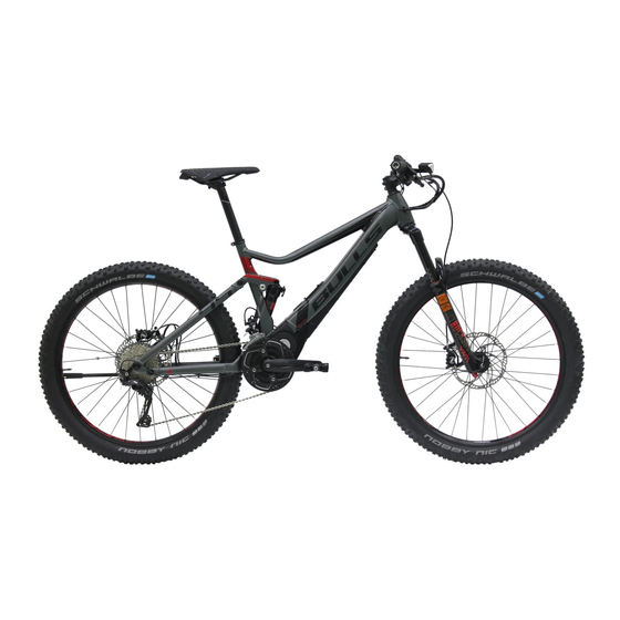
Description Description Overview 13 14 15 16 17 Figure 2: Vehicle on the right – E-Stream Evo 45 AM Front wheel Fork Handlebars Headlight Stem Frame Seat post Saddle Rear wheel Reflector, rear and brake light Registration plate Kickstand Chain Vehicle identification number Rear frame damper Battery... -
Page 22: Handlebars
Description Handlebars 9 10 Figure 3: Detailed view of vehicle from rider position, example Front brake lever Gear indicator Headlight Rear brake lever Mirror Command console Front shifter Display Rear shifter Horn 34-03141_1.0_11.06.2018... -
Page 23: Wheel And Fork
Description Wheel and fork Figure 4: Wheel components, example of front wheel Tyre Fork head with setting wheel Shock absorber Spoke Quick release Valve Fork end of the shock absorber 3.3.1 Valve Each wheel has a valve. It is used to fill the tyre with air. -
Page 24: Suspension
Description 3.3.2 Suspension A suspension fork has two functions which improve floor contact and comfort: suspension and damping. Figure 5: Vehicle without suspension (tension load) and with suspension (2) when riding over an obstacle The suspension prevents impacts such as those caused by a stone lying in the vehicle's path from being channelled directly into the rider's body via one of the forks. - Page 25 Description affects the wheel's contact with the ground, which, in turn, has an influence on control and efficiency. The damper should rebound fast enough to sustain traction without producing an erratic or bumpy sensation. If rebound damping is too strong, the damper is unable to rebound fast enough before the next impact.
-
Page 26: Fork Structure
Description 3.3.2.1 Fork structure The vehicle's fork features air suspension, a compression damper and a rebound damper. Figure 6: Yari fork – diagram with control elements: Air valve (1), valve cap (2) fork lock (3), quick release (4) and rebound damper adjuster (5) and the assembly groups: Air suspension fork (A), compression damper assembly group (B) and rebound damper assembly group (C) -
Page 27: Rear Frame Damper Structure
Description 3.3.2.2 Rear frame damper structure The rear frame damper features air suspension, a compression damper and a rebound damper. Figure 7: Exploded view drawing of RockShox Deluxe RT rear frame damper Guide rod eye Air valve Setting wheel Lever Air chamber O-ring 34-03141_1.0_11.06.2018... -
Page 28: Brake System
Description Brake system The vehicle is equipped with a hydraulic disk brake. Figure 8: Vehicle brake system with a disk brake, example Brake disc Brake caliper with brake linings Handlebars with brake levers Front wheel brake disc Rear wheel brake disc The brake disc is screwed permanently to the wheel hub on a vehicle with a disc brake. -
Page 29: Electric Drive System
Description Electric drive system The vehicle is driven by muscle power applied to the chain drive. The force which is applied by pedalling in the direction of travel, drives the front chain wheel. The chain transmits the force onto the rear chain wheel and then onto the rear wheel. - Page 30 Description Figure 10: Diagram of electric drive system Headlight Horn Display Command console Rear and brake light Motor Battery • a charger which is designed for this battery. As soon as the required muscle power from the rider pedalling passes a certain level, the motor is activated gently and assists the pedalling motion of the rider.
-
Page 31: Headlight
Description 3.5.1 Headlight The running light is automatically switched on when the drive is turned on and cannot be switched off. The headlight features a sensor, which allows the headlight to distinguish between DAYLIGHT and DARKNESS mode. DAYLIGHT mode The complete lamp unit is lit. The running light is lit in dimmed mode and the extra LEDs for daytime use are activated. -
Page 32: Display
Description 3.5.3 Display The display controls the drive system and shows the journey data. The vehicle's battery powers the display when the display is inserted in the mount, a sufficiently charged battery is used on the vehicle and the drive system is switched on. -
Page 33: Usb Port
Description 3.5.3.1 USB port There is a USB port underneath the rubber cover on the lower edge of the display. Charge voltage Charging current max. 500 mA Table 9: USB port technical data 3.5.3.2 Screen displays The display has ten screen displays: Figure 12: Overview of the screen displays Function display... - Page 34 Description Level of assistance The higher the selected level for assistance, the more the drive system assists the rider when pedalling. The following levels of assistance are available. Screen Level of assistance Table 11: Levels of assistance screen Current speed In the system settings, you can select whether the speed is displayed in kilometres or miles.
- Page 35 Description Screen Function Current time, displayed in hh:mm C LO C K Distance travelled since the last reset, T R I P D I S T A N C E displayed in kilometres or miles Calories burned since the last reset, T R IP K CA L displayed in calories Time elapsed since the last reset,...
-
Page 36: Command Console
Description System message The drive system monitors itself continuously and if an error is detected, it is indicated by a system message. The system may switch off automatically depending on the type of error. There is a table of system messages in the Appendix. -
Page 37: Rear And Brake Light
Description 3.5.5 Rear and brake light The rear light is automatically switched on when the drive is turned on and cannot be switched off. The brake light automatically indicates braking if a brake lever is pulled. 3.5.6 Battery The lithium ion battery has an internal electronic protection circuit. -
Page 38: Operating And Charge Status Indicator
Description The vehicle has an integrated battery. Figure 14: Integrated battery details Battery lock Port for charger plug On-Off button (battery) Operating and charge status indicator Top of down tube Battery 3.5.6.1 Operating and charge status indicator The five green LEDs on the operating and charge status indicator indicate the battery charge status when the battery is switched on. -
Page 39: Technical Data
Technical data Technical data Vehicle Weight 25.2 kg Maximum gross load weight 115.0 kg Transportation temperature 5 °C - 25 °C Ideal transportation temperature 10 °C - 15 °C Storage temperature 5 °C - 25 °C Ideal storage temperature 10 °C - 15 °C Operation temperature 5 °C - 35 °C Working environment temperature... -
Page 40: Display
Technical data Display Internal lithium ion battery 3.7 V, 240 mAh Storage temperature 5 °C - 25 °C Charging ambient temperature 10 °C - 30 °C Table 18: Display technical data Emissions A-weighted emission sound pressure level < 70 dB(A) Total vibration level for the hands <... -
Page 41: Fork
Technical data Fork Yari RC, Solo Air Part Tool or measurement Deflection 100 - 180 mm Damper Motion control Stanchion Oil type 5 WT Oil fill level 100 - 106 mm Volume 80 ml Lower fork leg Oil type OW-30 Volume 10 ml Spring... - Page 42 Technical data Deflection 150 mm/160 mm 170 mm/180 mm < 63 kg 55 - 65 psi 45 - 55 psi < 140 lbs 63 - 72 kg 65 - 75 ps 55 - 65 psi 140 - 160 lbs 72 - 81 kg 75 - 85 psi 65 - 75 ps 160 - 180 lbs...
-
Page 43: Brake
Technical data Rider's weight Full turns in an anti-clockwise direction < 54 kg 2.0 + 54 - 68 kg 1.5 - 2.0 68 - 82 kg 1.0 - 1.5 82 - 95 kg 0.5 - 1.0 < 95 kg 0.0 - 0.5 Table 24: Floodgate table Brake... -
Page 44: Tyres
Technical data Tyres Part Info or measurement Size designation ETRON 70-584 [27.5 x 2.8 inch] Tyre pressure* 120 - 260 kPa (1.20 - 2.60 bar) Table 26: Tyres technical data *After changing a tyre, you must consult the tyre markings for the permitted tyre pressures and make sure that they are observed. -
Page 45: Tightening Torque
Technical data 4.10 Tightening torque Part Tool Torque Axle nuts 35 Nm - 40 Nm Handlebars clamping 5 Nm - 7 Nm screw* Fork Handlebars clamping 5 Nm - 7 Nm screw maximum tightening torque* Air suspension guide 8 mm hex attachment and 3.0 - 3.6 Nm rod nut 12 mm socket nut... - Page 46 Technical data Locking screw for 2.5 mm hex attachment 0.85 Nm rebound adjustment ring Locking screw for 2 mm hex attachment 0.25 - 0.6 Nm remote control stop ring Caps 24 mm socket nut or 28 Nm RockShox top cap/cassette tool (or standard cassette tool) Rear frame damper...
- Page 47 Technical data Brake caliper T25 TORX® wrench 6 Nm attachment screw Pedals Crank screw Size 15 open-ended 34 Nm spanner Table 28: Tightening torque values 34-03141_1.0_11.06.2018...
-
Page 48: Transportation, Storage And Assembly
Transportation, storage and assembly Transportation, storage and assembly Transportation C ra sh c au s ed b y u n i n t e n t i o n a l a c t i v a t i o n CAUTION There is a risk of injury if the drive system is activated unintentionally. - Page 49 Transportation, storage and assembly Vehicle rack systems which secure the vehicle by its NOTICE handlebars or frame in an upside-down position exert inadmissible forces on the components during transportation. This can cause the supporting parts to break. Never use vehicle rack systems which secure the vehicle by its handlebars or frame in an upside-down position.
-
Page 50: Using The Transport Securing System
Transportation, storage and assembly 5.1.1 Using the transport securing system Insert two transport securing devices between the brake linings in each calliper. The transport securing device is squeezed between the two linings. Figure 15: Fastening the transport securing device Storing R i s k o f f i r e a n d e x p l o s i o n d u e t o h i g h CAUTION... -
Page 51: Break In Operation
Transportation, storage and assembly In the case of a vehicle with a hydraulic seat post, fix only the lower seat post or the frame into a fitting stand to prevent damage to the upper seat post and the seat post lever. -
Page 52: Preparing A Break In Operation
Transportation, storage and assembly 5.2.1.1 Preparing a break in operation Remove the battery from the vehicle. Charge the battery to around 60% (three to four LEDs of the charge status indicator light up). The vehicle needs to be cleaned with a damp cloth and preserved with wax spray. -
Page 53: Assembly
Transportation, storage and assembly Assembly C r u s h i n g c a u s e d b y u ni n t e n t i o n a l CAUTION a c t i v a t i o n There is a risk of injury if the drive system is activated unintentionally. -
Page 54: Unpacking
Transportation, storage and assembly 5.3.1 Unpacking Hand injuries caused by cardboard packaging CAUTION The shipping carton is closed with metal staples. There is a risk of puncture wounds and cuts when unpacking and crushing the packaging. Wear suitable hand protection. ... -
Page 55: Commissioning
Transportation, storage and assembly 5.3.3 Commissioning Fire and explosion caused by incorrect charger CAUTION Batteries which are charged with an unsuitable charger, may become internally damaged. This may result in fire or an explosion. Only ever use the battery with the supplied charger. ... -
Page 56: Initial Commissioning Check List
Transportation, storage and assembly 5.3.3.1 Initial commissioning check list Check battery [see Section 5.3.3.2, page 55]. The battery is supplied partially charged. In order to guarantee full power, charge the battery fully. Mount the wheels, quick release and pedals. ... -
Page 57: Checking The Battery
Transportation, storage and assembly 5.3.3.2 Checking the battery The battery has to be checked before it is charged for the first time. Press the On-Off button (battery). If none of the LEDs on the operating and charge status indicator light up, the battery may be damaged. -
Page 58: Adjust Vehicle To Rider
Adjust vehicle to rider Adjust vehicle to rider The ZEG specialist dealer checks all default settings and adjusts the saddle, handlebars, fork and the rear frame damper to the rider when the sale is made. Saddle 6.1.1 Determining the seat height Crash caused by an excessively high seat post CAUTION setting... -
Page 59: Clamping The Seat Post
Adjust vehicle to rider From an ergonomic point of view, the seat height should be set so that the heel touches the lowest point of the pedal when the leg is outstretched. Figure 17: Determining the saddle height 6.1.2 Clamping the seat post The ZEG specialist dealer demonstrates the function of the quick release to the rider or user. -
Page 60: Adjusting The Sitting Position And Saddle Tilt
Adjust vehicle to rider Only clamp the seat post when the vehicle is stationary. The seat post clamping lever is not marked with any lettering. You can tell whether it is open or closed from its shape. • To close it, push the seat post clamping lever as far as it will go into the seat post. -
Page 61: Brake Lever
Adjust vehicle to rider Brake lever 6.3.1 Adjusting the pressure point Brake failure due to incorrect setting WARNING If the pressure point is set with brakes where the brake lining and brake disc have reached their wear limit, the brakes may fail and cause an accident with injury. ... -
Page 62: Setting Grip Distance
Adjust vehicle to rider 6.3.2 Setting grip distance Brake failure due to incorrect setting WARNING If the brake lever is positioned too close to the handlebar grip, the full braking force cannot be applied. The brakes will fail, causing a crash and injuries. -
Page 63: Suspension And Damping
Adjust vehicle to rider Suspension and damping The adjustment shown here represents a basic setting. The rider should change the basic setting to suit the surface and his/her preferences. It is advisable to make a note of the basic setting. This way, it can be used as the starting point for subsequent, optimised settings and to safeguard against unintentional changes. -
Page 64: Front Wheel
Adjust vehicle to rider 6.4.1.1 Front wheel The air chamber valve can be used to adjust the fork suspension to the rider's weight and driving style. Adjusting tyre pressure The tyre pressure determines the force required to press the fork together. If the tyre pressure is reduced, the fork slackens more and rebounds less. - Page 65 Adjust vehicle to rider Adjusting sag Sag refers to the fork's deflection under the rider's weight. If the sag is set correctly, the front wheel can maintain better contact with the ground as you ride over rough terrain. If the positive tyre pressure increases, the sag also increases.
- Page 66 Adjust vehicle to rider Setting fork lock You can finely adjust the point where the fork lock is deactivated, so that the fork responds to impact caused by uneven surfaces or obstacles. The floodgate adjuster is used to adjust this point. The floodgate adjuster is yellow and is positioned in the middle of the fork lock.
-
Page 67: Rear Wheel
Adjust vehicle to rider Use the floodgate table to adjust to the optimal floodgate setting by turning anti-clockwise based on the rider's weight. Rider's weight Full turns in an anti-clockwise direction < 54 kg 2.0 + 54 - 68 kg 1.5 - 2.0 68 - 82 kg 1.0 - 1.5... - Page 68 Adjust vehicle to rider Only adjust the tyre pressure when the vehicle is stationary. Remove the valve cap. Use the high-pressure damper pump to raise the tyre pressure to the required level. Apply pressure (in psi) to the rear frame damper which matches the rider's overall weight in pounds, including their clothing.
-
Page 69: Setting The Rebound Damper
Adjust vehicle to rider There must be two people present to make this setting. The helper stabilises the vehicle. The rider climbs onto the vehicle. Deflect rear frame damper slightly 2-3 times. The helper pushes the O ring against the seal. ... -
Page 70: Front Wheel
Adjust vehicle to rider 6.4.2.1 Front wheel The rebound damper is set at the fork base. Figure 24: Rebound damper setting bolt (2) at the fork base (1) To do so, turn the rebound damper setting bolt all the way towards the hare symbol or the minus symbol. - Page 71 Adjust vehicle to rider Rear wheel The rebound damper for the rear wheel is located in the rear frame damper. Figure 25: Setting the rebound damper strength on the rear frame damper setting wheel (1) Turn the setting wheel to the middle position. ...
-
Page 72: Setting The Compression Damper
Adjust vehicle to rider 6.4.3 Setting the compression damper The compression damper controls the speed at which the rear frame damper deflects during slow impact, such as smaller impacts or when the rider goes round a corner or shifts their weight. The damper improves control and efficiency. -
Page 73: Rear Wheel
Adjust vehicle to rider 6.4.3.2 Rear wheel The lever is used to set the compression damper. • Turn the setting wheel in a clockwise direction (+) to decrease the deflection speed. Turn the setting wheel in an anti-clockwise direction (-) to increase the deflection speed. -
Page 74: Operation
Operation Operation Crash caused by loose clothing CAUTION Laces, scarves and other loose items may become entangled in the spokes on the wheels and the chain drive. Such damage may cause you to fall from the vehicle and injure yourself. ... - Page 75 Operation Heat or direct sunlight can cause the tyre pressure to NOTICE increase above the permitted maximum pressure. This can destroy the tyres. Never park the vehicle in the sun. On hot days, regularly check the tyre pressure and adjust it as necessary.
-
Page 76: Before Each Ride
Operation Before each ride Crash caused by difficult-to-spot damage CAUTION If the vehicle topples over or you have a fall or an accident, there may be difficult-to-spot damage to components such as the brake system, quick releases or frame. Such damage may cause you to fall from the vehicle and injure yourself. -
Page 77: Check List Before Each Ride
Operation 7.1.1 Check list before each ride Check that the vehicle is complete. Check that the lighting, reflector and brake, for instance, are sufficiently clean. You must check that the mudguards, the pannier rack and the chain guard are securely installed. Check that the front and rear wheels run true. -
Page 78: Using The Kickstand
Operation Using the kickstand Crash caused by a lowered kickstand CAUTION The kickstand does not fold up automatically. There is a risk of crashing if riding with the kickstand lowered. Raise the kickstand completely before the ride. The heavy weight of the vehicle may cause the NOTICE kickstand to sink into soft ground and the vehicle may topple and fall over. -
Page 79: Battery
Operation Battery Risk of fire and explosion due to faulty battery WARNING The safety electronics on damaged or faulty batteries may fail. The residual voltage can cause a short circuit. The batteries may self-ignite and explode. Remove batteries with external damage from service immediately and never charge them. - Page 80 Operation Fire and explosion caused by short circuit CAUTION Small metal objects may jumper the electrical connections of the battery. The batteries may self- ignite and explode. Keep paper clips, screws, coins, keys and other small parts away from the battery and do not insert them into the battery.
-
Page 81: Removing The Battery
Operation If a key is left inserted when transporting the vehicle, NOTICE or when riding, it may break off or the compartment may open accidentally. Remove the key from the battery lock immediately after use. We recommend that you attach the key to a key ring. -
Page 82: Charging The Battery
Operation 7.3.3 Charging the battery Fire caused by overheated charger CAUTION The charger heats up when charging the battery. In case of insufficient cooling, this can result in fire or burns to the hands. Never use the charger on a highly flammable surface (e.g. - Page 83 Operation Remove the rubber cover from the battery. Connect the mains plug of the charger to a normal domestic, grounded socket. 230 V, 50 Hz Connection data Connect the charging cable to the battery's charging port. The charging process starts automatically. ...
-
Page 84: Waking The Battery
Operation Risk of fire and explosion caused by CAUTION damaged batteries. The safety electronics on damaged or faulty batteries may fail. The residual voltage can cause a short circuit. The batteries may self-ignite and explode. If the battery becomes deformed or begins to smoke, keep at a safe distance, disconnect the power supply at the socket, and notify the fire service immediately. -
Page 85: Electric Drive System
Operation Electric drive system 7.4.1 Switching on the electric drive system Crash caused by lack of readiness for braking CAUTION When it is switched on, the drive system can be activated by the application of force on the pedals. There is a risk of a crash if the drive is activated unintentionally, and the brake is not reached. -
Page 86: Command Console With Display
Operation Command console with display 7.5.1 Display If the rider is not present, the display can be used NOTICE without authorisation, e.g. it may be stolen, the system settings may be changed or journey information may be read. Remove the display when the vehicle is parked. 7.5.1.1 Removing the display ... -
Page 87: Using The Usb Port
Operation 7.5.2 Using the USB port The USB port can be used to operate external devices which can be connected using a standard micro A/ micro B USB 2.0 cable. Open the protective flap on the USB port. Replace the protective flap after using the USB port. -
Page 88: Selecting The Level Of Assistance
Operation The push assist helps the rider to push the vehicle. The maximum speed can be 18 km/h here. Press and hold the push assist button for longer than three seconds. The push assist is activated. The push assist symbol is displayed. -
Page 89: Changing The System Information
Operation 7.5.6 Changing the system information Press and hold the headlight button for three seconds. Press the info button repeatedly until the journey information is displayed. Change values by pressing the minus and plus buttons. When the values are correct, press the info button briefly. -
Page 90: Gear Shift
Operation Gear shift The selection of the appropriate gear is a prerequisite for a physically comfortable ride and making sure that the electric drive system functions properly. The ideal pedalling frequency is between 40 and 60 revolutions per minute. Figure 29: Down shifter (1) and up shifter (2) on the left (I) and right (II) shift 7.6.1 Using the gear shift... -
Page 91: Brakes
Operation Brakes Crash caused by incorrect use CAUTION Handling the brake improperly can lead to loss of control or crashes, which may result in injuries. Practice braking and emergency braking before the vehicle is used in public spaces. Shift your weight back and down as far as possible. Crash caused by wet conditions CAUTION The tyres may slip on wet roads. -
Page 92: Braking
Operation The drive force of the motor is shut off during the ride as soon as the rider no longer pedals. The drive system does not switch off when braking. In order to achieve optimum braking results, do not pedal while braking. -
Page 93: Suspension And Damping
Operation Suspension and damping 7.9.1 Fork When the fork lock is in the open position, the suspension system is active, thus reducing impact on the rider and the vehicle. You should therefore preferably ride with the fork lock open when on terrain. The fork can only move slightly if the suspension is locked. -
Page 94: Opening The Fork Lock
Operation 7.9.1.2 Opening the fork lock If you wish to open the front wheel suspension, push the locking lever anti-clockwise and into the opened position. 7.10 Rear frame damper 7.10.1 Activating the threshold setting The threshold or pedalling setting prevents the damper from deflecting when there are slight impact or downward forces. - Page 95 Operation damper deflects if the acting force exceeds the damper's unlocking resistance. The lock setting is optimum to maximise pedalling efficiency on flat or hilly terrain. Figure 32: Activating the threshold setting with the lever (1) Only activate the lock setting while the vehicle is stationary.
-
Page 96: Wheel
Operation 7.1.1 Wheel Crash caused by unfastened quick release CAUTION A faulty or incorrectly installed quick release may become caught in the brake disc and block the wheel. This will cause a crash. Install the front wheel quick release lever on the opposite side to the brake disc. -
Page 97: Closing The Quick Release
Operation 7.1.1 Closing the quick release Place the quick release lever in the open position in the recess in the axle mouth. Figure 33: Placing the quick release lever (1) into the recess (2) Fasten the quick release on the quick release lever by hand in a clockwise direction and into the fork base. - Page 98 Operation Straighten the quick release lever and use two fingers to fasten the quick release. Move the quick release lever horizontally into the closed position. The quick release is now fastened. The lever is sufficiently fastened if the lever leaves an impression on your hand.
-
Page 99: Maintenance
Maintenance Maintenance Cleaning check list Clean rear frame damper after every ride Clean front wheel fork after every ride every Chain (mainly tarmacked road) 250–300 km every Chain (mainly off-road riding) 120–150 km Clean the battery once a month Basic cleaning and preservation of all at least every six... - Page 100 Maintenance at least every six Check for wear on brake discs months Inspection checklist 50-hour rear frame damper maintenance 50 hours (air chamber maintenance) 200-hour rear frame damper maintenance (maintenance of IFP chamber, damper body 200 hours and piston.
-
Page 101: Cleaning And Servicing
Maintenance Cleaning and servicing Crash and falling caused by unintentional activation CAUTION There is a risk of injury if the drive system is activated unintentionally. Remove the battery before cleaning. The following servicing measures must be carried out regularly. Servicing can be performed by the user and rider. -
Page 102: Basic Cleaning
Maintenance 8.1.2 Basic cleaning Crash caused by brake failure CAUTION The braking effect may be unusually weak temporarily after cleaning, servicing or repairing the vehicle. Such damage may cause you to fall from the vehicle and injure yourself. Never apply care products or oil to the brake discs or brake pads, or the braking surfaces on the rims. -
Page 103: Cleaning The Frame
Maintenance 8.1.2.1 Cleaning the frame Soak the entire frame with dish-washing detergent if the dirt is thick and ingrained. After leaving it to soak for a time, remove the dirt and mud with a sponge, brush and toothbrush.. ... -
Page 104: Cleaning The Chain
Maintenance 8.1.2.5 Cleaning the chain Never use aggressive (acid-based) cleaners, rust NOTICE removers or degreasers when cleaning the chain. Do not use chain cleaning devices or chain cleaning baths. Slightly dampen a brush with dish-washing liquid. Brush both sides of the chain. ... -
Page 105: Cleaning The Brake
Maintenance 8.1.2.7 Cleaning the brake Brake failure due to water penetration WARNING The brake seals are unable to withstand high pressures. Damaged brakes can fail and cause an accident with injury. Never clean the vehicle with a high-pressure water device or compressed air. -
Page 106: Servicing
Maintenance 8.1.3 Servicing 8.1.3.1 Servicing the frame Dry frame after cleaning Spray with care oil Clean off the care oil again after a short time. 8.1.3.2 Servicing the fork Treat the dust seals with fork oil 8.1.3.3 Servicing the drive elements ... -
Page 107: Maintenance
Maintenance Maintenance Crash and falling caused by unintentional activation CAUTION There is a risk of injury if the drive system is activated unintentionally. Remove the battery before maintenance. The following maintenance measures must be carried out regularly. They can be carried out by the user and rider. -
Page 108: Checking The Rims
Maintenance 8.2.1.3 Checking the rims Check the rims for wear. The rims are worn as soon as the black, all-round groove on the pad friction surface becomes invisible. Worn rims must be replaced by a ZEG specialist dealer. ... -
Page 109: Checking The Pressure Point
Maintenance Pull brake lever and hold. In doing so, check the transport safety wear gauge can fit between the brake lining supporting plates. The brake linings have not reached their wear limit. If they had, a ZEG specialist dealer would need to replace them. -
Page 110: Checking The Chain Tension
Maintenance 8.2.5 Checking the chain tension Excessive chain tension increases wear. NOTICE If the chain tension is too low, there is a risk that the chain will slip off the chain wheels. Check the chain tension once a month. ... -
Page 111: Checking The Usb Port Cover
Maintenance 8.2.7 Checking the USB port cover Any moisture which enters through the USB port may NOTICE trigger a short circuit in the display. Regularly check the position of the cover on the USB port and adjust it as necessary. 34-03141_1.0_11.06.2018... -
Page 112: Service
Maintenance Service Crash and falling caused by unintentional activation CAUTION There is a risk of injury if the drive system is activated unintentionally. Remove the battery before the service. Crash caused by material fatigue CAUTION If the service life of a component has expired, the component may suddenly fail. -
Page 113: Adjusting And Repairing
Maintenance Adjusting and repairing 8.4.1 Use original parts and lubricants only The individual vehicle parts have been carefully selected and matched to one other. Only original parts must be used for maintenance and repair. The constantly updated lists of approved accessories and parts are available to ZEG specialist dealers. -
Page 114: Rear Frame Damper
Maintenance 8.4.2 Rear frame damper Injury due to explosion WARNING The air chamber is pressurised. When the air system is serviced in a rear frame damper, it can explode and cause serious injury. Wear safety goggles, protective gloves and safety clothing when assembling or servicing the vehicle. - Page 115 Special tools, special lubricants and knowledge of suspension components are required to maintain and repair the rear frame damper. The rear frame damper https://www.bulls.de/service/downloads.html may become damaged if the procedure is not followed as described. Only ZEG specialist dealers may carry out maintenance on rear frame damper.
-
Page 116: Fork
Special tools, special lubricants and knowledge of suspension components are required to maintain and repair forks. The fork may become damaged if https://www.bulls.de/service/downloads.html procedures are not followed as described. Only ZEG specialist dealers may carry out maintenance on forks. You will find the maintenance and repair instructions https://www.bulls.de/service/downloads.html... -
Page 117: Wheel Quick Release
Maintenance 8.4.4 Wheel quick release 8.4.4.1 Setting the clamping force If the clamping lever cannot be pushed into its proper final position by hand, or if it is too loose, you need to readjust its clamping force. Figure 37: Setting the clamping force in the middle of the clamping lever (1) with a hexagon socket spanner (2) The fork may become damaged if the procedure is not followed as described. -
Page 118: Brake
Special tools, special lubricants and knowledge of suspension components are required to maintain and repair brake discs, such as venting brakes or replacing https://www.bulls.de/service/downloads.html the brake discs. The brakes may become damaged if procedures are not followed as described. Only ZEG specialist dealers may carry out maintenance on brakes. -
Page 119: Lighting
Replacing the lighting The ZEG specialist dealer must replace the entire light unit if an LED fails. You will find the repair instructions at: https://www.bulls.de/service/downloads.html 8.4.6.2 Setting the headlight The headlight must be set, so that its light beam meets the road 10 m in front of the vehicle. -
Page 120: Puncture And Protect Tyre
Maintenance 8.4.7.2 Puncture and protect tyre If a foreign body should cause a puncture, the tyre should be replaced and Schwalbe anti-puncture liquid should be used until it is replaced. Anti-puncture liquids are useful for repairing small punctures when out and about without dismounting the tube or tyre. -
Page 121: Repair By The Specialist Dealer
Maintenance 8.4.8 Repair by the specialist dealer Special knowledge and tools are required for many repairs. Only a ZEG specialist dealer must carry out the following repairs, for instance: • Replacing tyres and rims, • Replacing the brake pads and brake linings, •... -
Page 122: System Messages
Maintenance 8.4.9 System messages F i r e a n d e x p l o s i o n d u e t o f a u l t y b a t t e r i e s WARNING The safety electronics on damaged or faulty batteries may fail. -
Page 123: First Aid
Maintenance 8.4.9.1 First aid If an error message is displayed, run through the following actions: Make a note of the system message. Shut off and re-start the drive system. If the system message is still displayed, remove and then re-insert the battery. -
Page 124: First Aid
Maintenance 8.4.10 First aid 8.4.10.1 Electrical drive system does not start If the display and/or the drive system do not start up, proceed as follows: Check whether the battery is switched on. If not, start the battery. If the LEDs of the charge status indicator do not light up, contact the ZEG specialist dealer. - Page 125 Maintenance If the drive system does not start up, contact the ZEG specialist dealer. 34-03141_1.0_11.06.2018...
-
Page 126: Accessories
Maintenance Accessories Basic rules for attaching accessories We strongly advise Child seats against fitting a child seat for safety reasons. Trailer Not permitted Additional battery headlight Not permitted Use of baskets Not advisable Non-permanently attached bags on the Permitted pannier rack ... -
Page 127: Recycling And Disposal
Recycling and disposal Recycling and disposal Risk of fire and explosion WARNING The safety electronics on damaged or faulty batteries may fail. The residual voltage can cause a short circuit. The batteries may self-ignite and explode. Remove batteries with external damage from service immediately and never charge them. - Page 128 Recycling and disposal Hazard for the environment CAUTION The fork, rear frame damper and hydraulic brake system contain toxic and environmentally harmful oils and lubricants. These will contaminate if they enter the sewers or groundwater. Dispose of lubricants and oils in an environmentally responsible way in accordance with statutory regulations.
-
Page 129: Appendix
Hub, front Formula, DC-711, ALLOY ANODIZED, 6- www.formulahubs.com /contact BOLT TYPE, BOOST 110 mm 14 Gx32 H service@zeg.de Front and rear BULLS AS-T35 rims rims tubeless ready service@zeg.de Spokes, front BULLS STAINLESS BLACK, 14Gx32H; www.schwalbe.com/ Front and rear Schwalbe Nobby Nic en/kundenservice.html... - Page 130 Appendix Components Part Repair instructions si.shimano.com/#/en/ Pinion SHIMANO, CS-M8000- search/Series 11, 11-SPD, 11-40T service@zeg.de Crank MIRANDA CLASSIC, BROSE 170 MM; Q12 ISIS; BLACK MATT; # PD 22 IBT 17 CA 700001500 si.shimano.com/#/en/ Chainring set Shimano 44/30 T search/Series en.wellgopedal.com/ Pedals Wellgo C122-B pedals download_list.php?cid service@zeg.de...
- Page 131 #306/2KG-1, MOUNTON FORK service@zeg.de Kickstand HEBIE, #0665 E, E FIX service@zeg.de Registration ZEG supply plate holder service@zeg.de Stem BULLS stem service@zeg.de Handlebars BULLS handlebars service@zeg.de Handles TOPEAK/ERGON, GA30 BLACK, #43400090 service@zeg.de Rear mirror POLY AUTO TECHNOLOGY, FUXON M-1 MIRROR, www.bumm.de/de/...
-
Page 132: Table Of Figures
Appendix 10.2 Table of figures Figure 1: Type plate, example, 14 Figure 2: Vehicle on the right – E-Stream Evo 45 AM, 19 Figure 3: Detailed view of vehicle from rider position, example, 20 Figure 4: Wheel components, example of front wheel, 21 Figure 5: Vehicle without suspension (tension load) and with suspension (2) when riding over an obstacle, 22... - Page 133 Appendix Figure 27: Setting the compression damper strength using the rear frame damper setting lever (1), 71 Figure 28: Attach display (1) to the mount (3) by turning it in the direction of rotation indicated by the arrow (2), 84 Figure 29: Down shifter (1) and up shifter (2) on the left (I) and right (II) shift, 88...
-
Page 134: List Of Tables
Appendix 10.3 List of tables Table 1: Identification number of the operating instructions, 8 Table 2: Type number and model categorisation, 8 Table 3: Meanings of the signal words, 10 Table 4: Safety markings on the product, 11 Table 5: Information on the type plate, 11 Table 6: Simplified terms, 12... -
Page 135: Index
Appendix 10.4 Index Chain tension, 108 Fork, 22 Air chamber, 25 Chain wheel, 27 - adjusting sag, 63 Air valve Chain, 27 - adjusting tyre pressure, Fork, 24 - cleaning, 101, 104 Rear frame damper, 25 - maintaining, 108 - fork lock, 64 - replacing, 119 - setting the compression position 19... - Page 136 Appendix Kickstand, 19 Quick release, Saddle, 56 Position, 24 - adjusting the seat position 58 Level of assistance, 32 - changing the saddle tilt, - selecting, 86 Rear frame damper, Screen position, 31 - adjusting sag, 66 - changing the seat length, Lever, 25 - adjusting tyre pressure, - clamping the seat post...
- Page 137 Appendix Transporting, see Transportation Trip calories, 33 Position, 33 Trip distance, 33 Position, 33 Type number, 8 Tyres, - checking, 105 - replacing, 119 Position, 21 Technical data, 42 USB port, 31 - using, 85 Position, 30 Technical data, 38 Valve cap, 24 Valve, 21 Position, 21...
- Page 138 Text and images: ZEG Zweirad-Einkaufs-Genossenschaft eG Longericher Strasse 2 50739 Köln, Germany Translation: Tanner Translations GmbH+Co Markenstrasse 7 40227 Düsseldorf, Germany Operating instructions: 34-03141_1.0_11.06.2018...
- Page 139 WWW.BULLS.DE ZEG Zweirad-Einkaufs-Genossenschaft eG Longericher Straße 2 50739 Köln, Germany Tel.: +49 221 17959 0 YOUR BULLS SPECIALIST DEALER...
Need help?
Do you have a question about the E-Stream Evo 45 AM G 18 and is the answer not in the manual?
Questions and answers