Table of Contents
Advertisement
IMPORTANT
READ CAREFULLY BEFORE USE
KEEP SAFE FOR LATER REFERENCE
E l e c t r i c b i c y c l e
O P E R A T I N G
EN
I N S T R U C T I O N S
C r o s s E , C r o s s E 8 , U r b a n , G r i n d e r , T w e n t y 4 ,
A m i n g a , S i x 5 0 , T w e n t y 9 , M o n s t e r , C r u i s e r ,
C r o s s M o v e r S p e e d , C r o s s L i t e , I c o n i c ,
S e n t i n e l , S i x 5 0 E 2 S t r e e t
Advertisement
Table of Contents

Related Manuals for Bulls Cross E


Summary of Contents for Bulls Cross E
- Page 1 IMPORTANT READ CAREFULLY BEFORE USE KEEP SAFE FOR LATER REFERENCE E l e c t r i c b i c y c l e O P E R A T I N G I N S T R U C T I O N S C r o s s E , C r o s s E 8 , U r b a n , G r i n d e r , T w e n t y 4 , A m i n g a , S i x 5 0 , T w e n t y 9 , M o n s t e r , C r u i s e r , C r o s s M o v e r S p e e d , C r o s s L i t e , I c o n i c ,...
- Page 2 Copyright © BULLS Bikes USA Distribution or reproduction of these operating instructions and utilization or communication of their content is prohibited unless expressly approved. Any infringement will render the offender liable for compensation. All rights reserved in the event that a patent, utility model or...
- Page 3 Data sheet Name of the purchaser: Date of purchase: Model: Frame number: Type number: Unloaded weight (lbs): Tire size: Recommended tire pressure (psi)*: front: rear: Wheel circumference (mm): Company stamp and signature: *After a tire change, refer to the tire markings for the permitted tire pressures and make sure that they are observed.
- Page 4 Technical data Bicycle Transportation temperature 41°F - 77°F Ideal transportation temperature 50°F - 59°F Storage temperature 41°F - 77°F Ideal storage temperature 50°F - 59°F Operation temperature 41°F - 95°F Working environment temperature 59°F - 77°F Charging temperature 50°F - 86°F Power output/system 250 W (0.25 W) Shut-off speed - Class 1 bicycle...
- Page 5 Command console with display Internal cell batteries 3 V, 90 mAh Type CR2016 Storage temperature 14 °F to 140°F Table 3: Technical data for battery of the command console with display Emissions A-weighted emission sound pressure level < 70 dB(A) Total vibration level for the hands and <...
-
Page 6: Table Of Contents
Technical data About these instructions Manufacturer Laws, standards and directives Other valid documents Subject to change Language Identifying 2.6.1 Operating instructions 2.6.2 Bicycle For your safety 2.7.1 Instruction, training and customer service 2.7.2 Basic safety notes 2.7.3 Warnings 2.7.4 Safety markings For your information 2.8.1 Instructions for actions... - Page 7 4.4.2 Disc brake 4.4.3 Coaster brake Electric drive system 4.5.1 Battery 4.5.1.1 Operating and charge status indicator 4.5.2 Running light 4.5.3 Command console with display 4.5.3.1 USB port 4.5.3.2 Displays Transportation,storageandassembly Transportation Storing 5.2.1 Break in operation 5.2.1.1 Preparing a break in operation 5.2.1.2 Carrying out break in operation Assembly...
- Page 8 Operation Before each ride Using the kickstand Using the pannier rack Battery 7.4.1 Down tube battery 7.4.1.1 Removing the down tube battery 7.4.1.2 Inserting the down tube battery 7.4.2 Pannier rack battery 7.4.2.1 Removing the pannier rack battery 7.4.2.2 Inserting the pannier rack battery 7.4.3 Integrated battery 7.4.3.1...
- Page 9 Maintenance Cleaning and servicing 8.1.1 Battery 8.1.2 Display 8.1.3 Basic cleaning and preservation 8.1.4 Chain Maintenance 8.2.1 Wheel 8.2.2 Brake system 8.2.3 Electrical cables and brake cables 8.2.4 Gear shift 8.2.5 USB port 8.2.6 Chain or belt tension Service Correcting and repairing 8.4.1 Using original parts only 8.4.2...
- Page 10 Recycling and disposal EC declaration of conformity Table of figures Index...
-
Page 11: About These Instructions
Text passages which are directed expressly at specialist staff (e.g. bicycle mechanics), are clearly marked with a blue tool symbol. Staff at all BULLS specialist dealers have specialist training and qualifications, and are therefore capable of identifying risks and preventing hazards which may arise during maintenance, servicing and repairs on the bicycle. -
Page 12: Laws, Standards And Directives
The following document applies for this product: • Charger operating instructions. No other information is also applicable. The constantly updated lists of approved accessories and parts are available to BULLS specialist dealers. Subject to change The information contained in these operating instructions are the approved technical specifications at the time of printing. -
Page 13: Language
Language This operating instructions are written in English. A translation is not valid without this original operating instructions. -
Page 14: Identifying
Identifying 2.6.1 Operating instructions These operating instructions are printed in color. BULLS (BULLS Bikes USA) assumes no liability for copies of any kind, for example, black and white copies, loose pages or electronic copies. Table 6: Identification of the operating instructions 2.6.2... - Page 15 Six50 TR Street Class 1 Cross Lite EVO (Diam) Class 1 785-837XX Cross Lite EVO (ST) Cross Lite EVO (Wave) Class 1 Cross E (Wave) Class 1 785-599XX Twenty8 E45 (Diam) Class 3 790-946XX Twenty8 E45 (ST) Class 3 790-948XX...
-
Page 16: For Your Safety
If you are unable to contact your specialist dealer, you will find a list of BULLS specialist dealers on www.bullsebikes.com They will also be able to attend your customer service needs. -
Page 17: Basic Safety Notes
2.7.2 Basic safety notes These operating instructions have a chapter with general safety notes [ Chapter 3, page 21]. The chapter stands out because of its grey background. 2.7.3 Warnings Hazardous situations and actions are marked with warnings. The warnings in these operating instructions are shown as follows: Type and source of the danger SIGNAL WORD... -
Page 18: Safety Markings
2.7.4 Safety markings The following safety markings are used on the type plates of the bicycle: General warning Adhere to the instructions for use Table 9: Safety markings on the product For your information 2.8.1 Instructions for actions Instructions for actions are structured in accordance with the following pattern: Requirements (optional) ... - Page 19 only suitable for the road, no off-road riding or jumps suitable for roads, off-road riding and jumps of up to 15 cm suitable for rough off-road riding and jumps of up to 61 cm suitable for rough off-road riding and jumps of up to 122 cm suitable for the most difficult terrain Table 10:...
- Page 20 Read the instructions Separate collection of electrical and electronic devices Separate collection of batteries Must not be thrown into fire (burning prohibited) Battery must not be opened Device of protection class II Only suitable for use indoors Fuse (device fuse) EU conformity Recyclable material Protect from temperatures above 122 °F and...
-
Page 21: Language Conventions
2.8.3 Language conventions The bicycle described in these operating instructions may be equipped with alternative components. The equipment of the bicycle is defined by the respective type number. If applicable, the notes alternative equipment and alternative version make reference to the use of alternative components. -
Page 22: Type Plate
Type plate The type plate is situated on the frame. The type plate features the following information: CLASS 250W 20mph Figure 1: Type plate, example Identification Classification Maximum power output Shut-off speed Classification (1) A “class 1 electric bicycle,” or “low-speed pedal-assisted electric bicycle,”... -
Page 23: Safety
Safety Requirements for the rider If there are no legal requirements for the rider of electrically power assisted cycles, we recommend that the rider should be a minimum 15 years of age and have experience with muscle-powered bicycles. The physical and mental abilities of the rider must be sufficient for the use of a muscle-powered bicycle. -
Page 24: City And Trekking Bicycle
3.2.1 City and trekking bicycle City and trekking bicycles are designed for daily, comfortable use on asphalted roads and paths. They are suitable for riding on public roads. City and trekking bicycles are not sports bicycles. If used for sports, reduced riding stability and diminished comfort are to be expected. -
Page 25: Duty Of Care
Rider The rider: • receives instruction before the first ride. He/she can clarify any questions relating to the operating instructions with the user or the BULLS specialist dealer. • wears personal protective equipment. • assumes all the responsibilities of the user when... -
Page 26: User
3.6.2 User The user has the duty of care and responsibility for scheduling these measures and checking that they are implemented. The user: • makes these operating instructions available to the rider for the duration of use of the bicycle. If necessary, he translates the operating instructions into a language which the rider understands. -
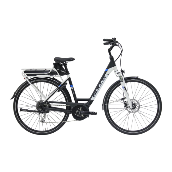
Page 27: Description Overview
Description Overview Figure 2: Bicycle, viewed from the right, example of Six50 Front wheel Fork Front mudguard Handlebars Stem Frame Seat post Saddle Reflector Pannier rack Rear mudguard Kickstand Rear wheel Chain Frame number and type plate Battery... -
Page 28: Handlebars
Handlebars Figure 3: Detailed view of bicycle from rider position, example Front brake lever Bell Lamp Front brake lever Command console with display Fork lock Shifter... -
Page 29: Wheel And Fork
Wheel and fork Figure 4: Components of the wheel, example of front wheel Tire Preload adjuster Shock absorber Spoke Quick release Valve Fork end of the shock absorber 4.3.1 Valve Each wheel has a valve. It is used to fill the tire with air. -
Page 30: Suspension
4.3.2 Suspension A suspension fork has two functions which improve the floor contact and the comfort: the suspension and the damping. Figure 5: Bicycle without suspension (1) and with suspension (2) when riding over an obstacle The suspension prevents an impact, e.g. caused by a stone lying in the way, from being directed directly into the rider's body via a fork. - Page 31 This model series features up to three different suspension and damping systems: Figure 6: Arrangement of the suspension systems for the front wheel (I) and rear wheel (II) Suspension system (steel suspension fork or air suspension fork) Compression damper Rebound damper Fork housing...
-
Page 32: Brake System
Brake system The bicycle's brake system comprises: • a rim brake on the front and rear wheels, • a disc brake on the front and rear wheels or • a rim brake on the front and rear wheels and an additional coaster brake. -
Page 33: Locking Lever
Figure 8: Rim brake locking lever, on rear wheel (1) and front wheel (2) The locking levers are not labelled. The locking levers must only be set by a BULLS specialist dealer. -
Page 34: Disc Brake
4.4.2 Disc brake (Alternative equipment) Figure 9: Bicycle brake system with a disc brake, example Disc brake Brake caliper with brake linings Handlebars with brake levers Front wheel disc brake Rear wheel disc brake On a bicycle with a disc brake, the brake rotor is fixed to the hub of the wheel. -
Page 35: Coaster Brake
4.4.3 Coaster brake (Alternative equipment) Figure 10: Brake system with a coaster brake, example Rear wheel rim brake Handlebars with brake levers Front wheel rim brake Pedal Coaster brake The coaster brake stops the movement of the rear wheel when the rider pedals in the opposite direction to the direction of travel. -
Page 36: Electric Drive System
Electric drive system The bicycle is driven by muscle power via the chain drive. The force which is applied by pedaling in the direction of travel, drives the front chain ring. The chain transmits the force onto the cassette and then onto the rear wheel. - Page 37 The electric drive system is made up of six components: Figure 12: Diagram of electric drive system Lamp Command console with display Down tube battery Rear light Motor • a charger which is designed for this battery. As soon as the required muscle power from the rider pedaling passes a certain level, the motor is activated gently and assists the pedaling motion of the rider.
-
Page 38: Battery
The bicycle does not have a separate EMERGENCY STOP or EMERGENCY SHUT-OFF button. The drive system with removable display can be stopped in case of emergency by removing the display. The motor switches off automatically as soon as the rider no longer pedals, the temperature is outside the permitted range, there is an overload or the shut-off speed limit has been reached. - Page 39 41°F - 77°F Transportation temperature Ideal transportation temperature 50°F - 59°F 41°F - 77°F Storage temperature Ideal storage temperature 50°F - 59°F Charging ambient temperature 50°F - 86°F Table 15: Battery technical data The bicycle has a down tube battery. Figure 13: Details of the down tube battery Battery housing...
-
Page 40: Operating And Charge Status Indicator
4.5.1.1 Operating and charge status indicator The five green LEDs of the operating and charge status indicator indicate the charge status when the battery is switched on. Each LED represents 20% of the charge status. The charge status of the activated battery is also shown on the display. - Page 41 The pane of glass on the display may steam up from the inside in the event of abrupt temperature fluctuations. This is not a malfunction. The command console with display has four buttons. L K K K K K L L K K K K W W A W W W W W W A A...
-
Page 42: Usb Port
4.5.3.1 USB port Test instruments can be connected to the USB diagnostics port to check the drive system. The USB diagnostics port does not have any other functions. 4.5.3.2 Displays The command console with display has seven display screens: Figure 15: Overview of the screen displays Unit of speed Current speed... - Page 43 Level of assistance The higher the level of assistance, the more the drive system assists the rider when pedaling. The following levels of assistance are available. Level of assistance When the drive system is switched on, the motor assistance is switched off. O F F The pushing aid cannot be activated with this level of assistance.
- Page 44 Journey information The command console with display shows one of three items of journey information. The displayed item of journey information can be switched Display Function TR IP Distance travelled since the last RESET TO T AL Display of the total distance travelled (cannot be changed) RAN G E Anticipated range of the available...
-
Page 45: Transportation,Storageandassembly
Transportation, storage and assembly Transportation C r a s h c a u s e d b y u ni n t e n t i o n a l a c t i v a t i o n CAUTION There is a risk of injury if the drive system is activated unintentionally. - Page 46 When transporting by car, you must use a suitable bicycle rack system. The BULLS specialist dealer will advise you on how to select a suitable rack system properly and how to use it safely.
-
Page 47: Storing
Storing R i s k o f f i r e a n d e x p l o s i o n d u e t o h i g h CAUTION t e m p e r a t u r e s Excessively high temperatures damage the battery. -
Page 48: Preparing A Break In Operation
Never wax the friction surfaces of the brake. Before longer periods without use, it is ü recommendable for the BULLS specialist dealer to carry out servicing, basic cleaning and to apply preservative agent. 5.2.1.2 Carrying out break in operation ... -
Page 49: Assembly
Universal tools, a torque wrench with an operating ü range of 5 Nm to 40 Nm and the special tools, as recommended by BULLS, must be available. 5.3.1 Unpacking Hand injuries caused by cardboard packaging CAUTION The shipping carton is closed with metal staples. -
Page 50: Scope Of Delivery
The packaging has to be disposed of in accordance with the regulations of the authorities. 5.3.2 Scope of delivery The bicycle was completely assembled in the factory for test purposes and then dismantled for transportation. The scope of delivery includes: •... - Page 51 Initial commissioning includes the following work: Check the battery [ Chapter 5.3.3.1, page 50]. The battery is supplied partially charged. In order to guarantee full power, charge the battery fully. Install the wheels with quick release and the pedals. ...
-
Page 52: Checking The Battery
Sale of the bicycle Fill out the data sheet on the first page of the operating instructions. Adjust the bicycle to the rider. Set the kickstand and the shifter, and show the purchaser the settings. Instruct the user or rider how to use all the functions of the bicycle. - Page 53 Crash caused by faulty or incorrectly installed quick CAUTION release The disc brake becomes very hot during operation. Parts of the quick release may become damaged as a result. The quick release may loosen up and ultimately this could result in an crash accident. u The front wheel quick release lever and the brake rotor must be situated on opposite sides.
-
Page 54: Adjustingthebicycletotherider
Adjusting the bicycle to the rider The BULLS specialist dealer checks all the factory settings and, when the bicycle is sold, adapts the settings of the saddle, handlebars, suspension fork and the spring damper elements to the rider. Adjusting the saddle 6.1.1... -
Page 55: Clamp The Seat Post With The Quick Release
Figure 17: Determining the saddle height 6.1.2 Clamp the seat post with the quick release The BULLS specialist dealer demonstrates the function of the quick release to the rider or user. Figure 18: Seat post quick release in the final position... -
Page 56: Adjusting The Sitting Position And Saddle Tilt
Check the clamping force of the quick releases. 6.1.3 Adjusting the sitting position and saddle tilt Special tools are required to adjust the seat length and the saddle tilt. The BULLS specialist dealer adjusts the saddle setting to the rider. Setting the handlebars ... -
Page 57: Setting The Stem With Quick Release
Setting the stem with quick release (Alternative version) Crash caused by incorrectly set clamping force CAUTION Excessively high clamping force will damage the quick release and cause it to lose its function. Insufficient clamping force will cause a detrimental transmission of force. This can cause components to break. -
Page 58: Checking The Clamping Force Of The Quick Releases
If the clamping force of the clamping lever on the seat post is not sufficient, screw in the knurled nut. If the clamping force cannot be set, the BULLS specialist dealer will need to check the quick release. -
Page 59: Basic Setting For Suspension And Damping
Basic setting for suspension and damping The adjustment shown here represents a basic setting. The rider should change the basic setting to suit the surface and his/her preferences. It is recommendable to make a note of the basic setting. This way, it can be used as the starting point for subsequent, optimised settings and to safeguard against unintentional changes. -
Page 60: Adjusting The Hardness Of The Air Suspension Elements
6.5.1.2 Adjusting the hardness of the air suspension elements Riding without filling pressure will destroy the NOTICE suspension, the frame, and the air suspension components. Never ride without filling pressure in the air suspension elements. A normal air pump cannot build up the required NOTICE pressure with sufficient sensitivity. - Page 61 The ideal setting for the weight of the rider has been achieved when the measured position is between 20 - 30%. For fine setting, adjust the filling pressure using the fork valve. Screw the screw cover back on. Rear wheel ...
- Page 62 Figure 22: Setting the hardness on the suspension damping element Dial Valve cap on suspension damping element O-ring...
-
Page 63: Setting The Rebound Damper
6.5.2 Setting the rebound damper Front wheel The rebound damper for the front wheel is situated on the fork leg. It may be marked with either hare/ tortoise symbols or plus and minus symbols. Figure 23: Setting the rebound damper, example with hare and tortoise symbol Setting bolt Tortoise symbol... - Page 64 If the wheel loses contact with the floor, turn back in small steps towards the tortoise symbol or plus symbol. Rear wheel The rebound damper for the rear wheel is situated on the suspension damping element. Figure 24: Setting the hardness on the suspension damping element Setting wheel Hare symbol Tortoise symbol...
-
Page 65: Setting The Compression Damper
6.5.3 Setting the compression damper The basic setting only has to be determined for compression dampers which have to be set with multiple clicks. A setting of 5 clicks is recommended as the basic setting. Response of the Setting damper sensitive select opened damping or low pressure level... -
Page 66: Setting The Grip Distance Of The Brake Lever
Never adjust the position of the brake cylinder without special tools. Have a BULLS specialist dealer carry out the adjustment. u Set the slider to one of the three positions with the brake lever gently applied. -
Page 67: Hydraulically Operated Disc Brake
6.6.2 Hydraulically operated disc brake (Alternative equipment) Set the grip distance using the knurled screw on the brake lever. The rider can use the brake lever comfortably. Figure 27: Brake lever (1) with knurled screw (2) -
Page 68: Operation
Operation Crash caused by loose clothing CAUTION Laces, scarves and other loose items may become entangled in the spokes on the wheels and the chain drive. This may result in a crash and injuries. Wear sturdy footwear and close-fitting clothing. Crash caused by accumulated dirt CAUTION Accumulated dirt can disrupt the functions of the... - Page 69 Paths in poor condition subject the joints in the arms to severe strain. Take a break from riding every 30 to 90 minutes, depending on the condition of the roads.
-
Page 70: Before Each Ride
This may result in a crash and injuries. Remove the bicycle from service immediately in case of any signs of material fatigue. Have a BULLS specialist dealer check the situation. u Have the BULLS specialist dealer carry out basic cleaning regularly. - Page 71 Check list before each ride Check that the bicycle is complete. Check that the lighting, reflector and brake, for instance, are sufficiently clean. You must check that the mudguards, the pannier rack and the chain guard are securely installed. Check that the front and rear wheels run true.
-
Page 72: Using The Kickstand
Using the kickstand Crash caused by a lowered kickstand CAUTION The kickstand does not fold up automatically. There is a risk of crashing if riding with the kickstand lowered. Raise the kickstand completely before the ride. Because of the heavy weight of the bicycle, the NOTICE kickstand may sink into soft ground, the bicycle may topple and fall over. -
Page 73: Using The Pannier Rack
Using the pannier rack (Alternative equipment) Crash caused by loaded pannier rack CAUTION The riding performance of the bicycle changes with a loaded pannier rack, in particular when steering and braking. This can lead to a loss of control. This may result in a crash and injuries. - Page 74 The maximum load bearing capacity is indicated on the NOTICE pannier rack. Never exceed the permitted total weight when packing the bicycle. Never exceed the maximum load bearing capacity of the pannier rack. Never modify the pannier rack. ...
-
Page 75: Battery
Battery Risk of fire and explosion due to faulty battery WARNING The safety electronics on damaged or faulty batteries may fail. The residual voltage can cause a short circuit. The batteries may self-ignite and explode. Remove batteries with external damage from service immediately and never charge them. - Page 76 Fire and explosion caused by short circuit CAUTION Small metal objects may jumper the electrical connections of the battery. The batteries may self- ignite and explode. Keep paper clips, screws, coins, keys and other small parts away from the battery and do not insert them into the battery.
-
Page 77: Down Tube Battery
If a key is left inserted when transporting the bicycle, NOTICE or when riding, it may break off or the compartment may open accidentally. Remove the key from the battery lock immediately after use. We recommend that you attach the key to a key ring, for example. -
Page 78: Pannier Rack Battery
7.4.2 Pannier rack battery (Alternative version) Before the battery is to be removed or inserted, switch off the battery and the drive system. 7.4.2.1 Removing the pannier rack battery Open the battery lock with the key. Pull the pannier rack battery backwards and out of the pannier rack battery mount. -
Page 79: Inserting The Integrated Battery
7.4.3.2 Inserting the integrated battery Place the battery in the bottom mount with the contacts first. Flip the integrated battery up so that it is held by the retainer guard. Push the integrated battery upwards so that it audibly clicks into place. - Page 80 Electric shock in case of damage CAUTION Damaged chargers, cables and plug connectors increase the risk of electric shock. Check the charger, cable and plug connector before each use. Never use a damaged charger. u The ambient temperature during the charging process must be within the range from 50°F to 86°F.
-
Page 81: Waking The Battery
Risk of fire and explosion caused by CAUTION damaged batteries. The safety electronics on damaged or faulty batteries may fail. The residual voltage can cause a short circuit. The batteries may self-ignite and explode. If the battery becomes deformed or begins to smoke, keep at a safe distance, disconnect the power supply at the socket, and notify the fire service immediately. -
Page 82: Electric Drive System
Electric drive system 7.5.1 Switching on the drive system Crash caused by lack of readiness for braking CAUTION A drive system which has been switched on can be activated by the application of force on the pedals. There is a risk of a crash if the drive is activated unintentionally, and the brake is not reached. -
Page 83: Switching Off The Drive System
7.5.2 Switching off the drive system The system switches off automatically ten minutes after the last command. The are two options for switching off the drive system manually. 1 Display On-Off key Press the On-Off button (command console with integrated display) once. -
Page 84: Command Console With Display
Command console with display (Alternative version) 7.6.1 Using the USB diagnostics port Test instruments can be connected to the USB NOTICE diagnostics port to check the drive system. The USB diagnostics port does not have any other functions. Never connect a charger or current consumer (e.g. mobile phone or computer) to the USB diagnostics port. -
Page 85: Using The Running Light
Switching off the pushing aid The pushing aid is switched off in case of three events. The plus button is released. • • The wheels are blocked. • At speeds above 3.75 mph 7.6.3 Using the running light To switch on the running light, the drive system has to be switched on already. -
Page 86: Switching The Displayed Journey Information
7.6.5.1 Switching the displayed journey information Press and hold the minus button (command console with display) again for around two seconds, until the desired item of journey information is displayed. 7.6.5.2 Resetting the journey distance Press and hold the plus and minus buttons simultaneously for around three seconds. -
Page 87: Gear Shift
Gear shift The selection of the appropriate gear is a prerequisite for a physically comfortable ride and making sure that the electric drive system functions properly. The ideal pedaling frequency is between 40 and 60 revolutions per minute. Select the appropriate gear with the gear shift shifter. -
Page 88: Brakes
Brakes Crash caused by incorrect use CAUTION Handling the brake improperly can lead to loss of control or crashes, which may result in injuries. Shift your weight back and down as far as possible. Practise braking and emergency braking before the bicycle is used in public spaces. -
Page 89: Using The Coaster Brake
7.8.2 Using the coaster brake (Alternative equipment) The best braking effect is achieved if the pedals are in the 3 o'clock and 9 o'clock position when braking. To bridge the free travel between the riding movement and the braking movement, it is recommendable to pedal a little beyond the 3 o'clock and 9 o'clock position before you pedal in the opposite direction to the direction of travel and start braking. -
Page 90: Suspension And Damping
Suspension and damping 7.9.1 Locking the front wheel suspension (Alternative equipment) When the fork lock is in the open position, the suspension system has activated suspension and thus provides the rider and the bicycle with relief. Riding with the fork lock open should therefore be preferred for everyday riding. -
Page 91: Locking Lever On Handlebars, Version I
7.9.1.2 Locking lever on handlebars, version I To lock the suspension system, push the locking slider out of the pushed-in position. The locking slider stops in the pushed-out position. A padlock symbol indicates that the fork lock is locked. -
Page 92: Fork Lock On Handlebars, Version Iii
7.9.1.4 Fork lock on handlebars, version III To lock or release the front wheel suspension, push the long lever. To reset the function of the long lever, push the short lever. Figure 31: Fork lock on handlebars, version III, with long lever (1) and short lever (2), example 7.9.1.5 Fork lock on handlebars, version IV... -
Page 93: Locking The Compression Damper
The locking lever features a closed padlock symbol. To release the front wheel suspension, push the side unlocking lever. The side unlocking lever features an open padlock symbol. Figure 33: Fork lock on handlebars, version V, with locking lever (1) and unlocking lever (2) 7.9.2 Locking the compression damper... - Page 94 Maintenance Cleaning check list Lubricating the chain once a month Cleaning the battery once a month Basic cleaning and preservation of all at least every six components months Cleaning the charger at least every six months Maintenance check list Checking the position of the USB rubber cover before each ride ...
-
Page 95: Cleaning And Servicing
The following servicing measures must be carried out regularly [ Check list, page 92]. Servicing can be performed by the user and rider. In case of any doubt, consult the BULLS specialist dealer. 8.1.1 Battery Fire and explosion caused by penetration by water CAUTION The battery is only protected from simple spray water. -
Page 96: Basic Cleaning And Preservation
Carefully clean the display with a damp, soft cloth. 8.1.3 Basic cleaning and preservation Crash caused by brake failure CAUTION After cleaning, servicing or repairing the bicycle, the braking effect may be temporarily unusually weak. This may result in a crash and injuries. ... -
Page 97: Maintenance
[ Check list, page 92]. They can be carried out by the user and rider. In case of any doubt, consult the BULLS specialist dealer. 8.2.1 Wheel If the pressure is too low in the tire, the tire does not NOTICE achieve its load bearing capacity. -
Page 98: Brake System
8.2.2 Brake system u On bicycles with a rim brake, check the position of the brake pads. The brake pads must be aligned exactly to the rims. Replace the brake pads on the rim brake when the profile (check notches) has reached a remaining depth of 1 mm. -
Page 99: Chain Or Belt Tension
If the chain or the belt can be pushed more than 2 cm, the chain or belt will need to be tensioned again by the BULLS specialist dealer. u If the chain or the belt can only be pushed less than 1 cm, the chain or belt will need to be relieved of tension accordingly. -
Page 100: Service
If the service life of a component has expired, the component may suddenly fail. This may result in a crash and injuries. u Have the BULLS specialist dealer carry out six- monthly basic cleaning of the bicycle, preferably at the same time as the stipulated servicing work. -
Page 101: Correcting And Repairing
Using original parts only The individual parts of the bicycle have been carefully selected to matched each other. Only original parts must be used for maintenance and repair. The constantly updated lists of approved accessories and parts are available to BULLS specialist dealers. -
Page 102: Wheel Quick Release
8.4.2 Wheel quick release Crash caused by unfastened quick release CAUTION A faulty or incorrectly installed quick release may become caught in the disc brake and block the wheel. This will cause a crash. u Install the front wheel quick release lever on the opposite side to the disc brake. -
Page 103: Clamping The Clamping Lever
8.4.2.1 Clamping the clamping lever The clamping lever for the quick release is marked OPEN and CLOSE. If you can read the word OPEN, the quick release is open. If you can read the word CLOSE, the quick release is clamped. ... -
Page 104: Clamping Version Ii
Checking and setting the clamping force of the quick releases If the clamping lever cannot be moved into the final position just by pushing it with the hand, or if it is too loose, its clamping force will need to be readjusted. The clamping lever is completely open. - Page 105 Clamping version III If the clamping force is insufficient, have the NOTICE BULLS specialist dealer inspect it. Figure 38: Quick release, version III, with axle (1) and clamping lever (2) Push the axle into the hub as far as it will go with the clamping lever completely open.
-
Page 106: Clamping Version Iv
8.4.2.5 Clamping version IV Push the axle into the hub as far as it will go with the clamping lever open. Screw the clamping lever clockwise into the correct final position. Clamp the clamping lever. Setting the clamping force If the clamping force is set too high, the clamping lever cannot be pushed into the closed final position. - Page 107 8.4.2.6 Clamping version V Crash caused by unfastened quick release CAUTION The clamping force of the quick release lever is set once during assembly and is not an indication that the wheel axle is sufficiently fastened. The axle may come loose if the closed quick release is turned.
- Page 108 Turn the axle on the quick release clockwise until the axle is firmly in place. Pull the lever from the recess and clamp it properly. The clamping force of the lever is not an indication of the tightening torque of the axle. Setting the clamping force If the clamping lever cannot be moved into its proper final position by pushing it with the hand, or if it is too...
- Page 109 Open the quick release lever. Connect a 2.5 mm hexagon socket spanner to the middle of the clamping lever. Turn the hexagon socket spanner: • clockwise to increase the clamping force and • anti-clockwise to reduce the clamping force. ...
-
Page 110: Adjusting The Tire Pressure
8.4.3 Adjusting the tire pressure 8.4.3.1 Dunlop valve The tire pressure cannot be measured on the simple Dunlop valve. The tire pressure is therefore measured in the filling hose when pumping slowly with the bicycle pump. It is recommendable to use a bicycle pump with a pressure gauge. -
Page 111: Presta Valve
8.4.3.2 Presta valve It is recommendable to use a bicycle pump with a pressure gauge. The operating instructions for the bicycle pump must be adhered to. u Unscrew and remove the valve cap. u Open the knurled nut around four turns. u Carefully apply the bicycle pump so that the valve insert is not bent. -
Page 112: Schrader Valve
8.4.3.3 Schrader valve It is recommendable to use a bicycle pump with a pressure gauge. The operating instructions for the bicycle pump must be adhered to. u Unscrew and remove the valve cap. u Connect the bicycle pump. u Pump up the tire slowly and pay attention to the tire pressure in the process. -
Page 113: Adjusting The Gear Shift
Check the function of the gear shifting after each adjustment. If the gear shift cannot be set this way, the assembly of the gear shift will need to be inspected by a BULLS specialist dealer. 8.4.4.1 Cable-operated gear shift, single-cable (Alternative version) u For a smooth gear shift, adjust the barrel adjuster on the gear shift housing. -
Page 114: Cable-Operated Gear Shift, Dual-Cable
8.4.4.2 Cable-operated gear shift, dual-cable (Alternative version) For a smooth gear shift, set the adjusting sleeves underneath the chain stay on the frame. The shift cable has play of approximately 1 mm when it is pulled out gently. Figure 47: Adjusting sleeves (2) on two alternative versions (A and B) of a dual-cable cable-operated gear shift on the chain stay (1) -
Page 115: Cable-Operated Twist Grip, Dual-Cable
8.4.4.3 Cable-operated twist grip, dual-cable (Alternative version) For a smooth gear shift, set the adjusting sleeves on the gear shift housing. There is noticeable play of around 2 - 5 mm (1/2 gear) when twisting the twist grip. Figure 48: Twist grip with adjusting sleeves (1) and play of the gear shift (2) -
Page 116: Replacing The Lighting
10 m in front of the bicycle. 8.4.7 Repair by the specialist dealer Special knowledge and tools are required for many repairs. Only a BULLS specialist dealer must carry out the following repairs, for instance: • Replacing tyres and rims, •... -
Page 117: First Aid For System Messages
Shut off and re-start the drive system. u If the system message is still displayed, remove and then re-insert the battery. u Re-start the drive system. u If the system message is still displayed, contact the BULLS specialist dealer. -
Page 118: Specific Fault Eradication
Specific fault eradication Make a note of the system message. Fault Remedy LOW BAT Replace the internal display battery Contact the BULLS specialist dealer. 540, The bicycle is outside the permitted temperature 604, range. Switch off the bicycle. - Page 119 If the LEDs of the charge status indicator do not light up, contact the BULLS specialist dealer. u If the LEDs of the charge status indicator light up, but the drive system does not start up, remove the battery.
-
Page 120: Accessories
Accessories We do not recommend to equip a full suspension bicycle with a kickstand. We recommend a parking stand into which either the front or rear wheel can be inserted securely. -
Page 121: Child Seat
8.5.1 Child seat Crash caused by improper handling CAUTION When using child seats, the riding properties and the stability of the bicycle change considerably. This can cause a loss of control, a crash and injuries. You should practice how to use the child seat safely and reliably before using the bicycle in public spaces. - Page 122 The BULLS specialist dealer will advise you on the choice of right child seat system for the child and the bicycle. The scope of delivery of commercially available child seats does not usually contain any of the material which is required to adapt the bicycle to the child seat.
-
Page 123: Bicycle Trailer
The BULLS specialist dealer will advise you on the choice of right trailer system for the bicycle. The scope of delivery of commercially available bicycle trailers does not usually contain any of the material which is required to adapt the bicycle to the trailer. - Page 124 Recycling and disposal Risk of fire and explosion WARNING The safety electronics on damaged or faulty batteries may fail. The residual voltage can cause a short circuit. The batteries may self-ignite and explode. Remove batteries with external damage from service immediately and never charge them.
- Page 125 The bicycle, the display, the unopened and undamaged battery and the charger can be returned to any BULLS specialist dealer free of charge. Depending on the region, further disposal options may be available. u Store the individual parts of the decommissioned bicycle in a dry place, free from frost, where they are protected from direct sunlight.
- Page 127 Table of figures Figure 1: Type plate, example, 20 Figure 2: Bicycle, viewed from the right, example of Six50, 25 Figure 3: Detailed view of bicycle from rider position, example, 26 Figure 4: Components of the wheel, example of front wheel, 27 Figure 5: Bicycle without suspension (1) and with suspension (2) when riding over an obstacle, 28...
- Page 128 Figure 30: Fork lock on handlebars, version II, with locking lever (1) and unlocking lever (2) (example), 89 Figure 31: Fork lock on handlebars, version III, with long lever (1) and short lever (2), example, 90 Figure 32: Fork lock on handlebars, version IV, with locking lever (1) and unlocking knob (2), 90 Figure 33: Fork lock on handlebars, version V, with locking lever (1)
- Page 129 Index Charge status indicator, 38 Alternative equipment, 19 Charger, Gear shift twist grip, Alternative version, 19 - disposing of, 123 - checking, 96 Clamping force, Gear shift, - Checking the quick - maintaining, 96 Braking: coaster 30, 32, 33 releases, 102 - switching, 85 -braking, 87 - Setting the quick...
- Page 130 Shifter, 26 On-Off button, - checking, 96 Display, 39 - setting, 98, 110, 111 Operating status indicator, 38 Spoke, 27 Storage, 45 Storing, see Storage Packaging, 47 Suspension fork, 28 Pannier rack, 25 - locking, 88 - checking, 69 Suspension head, 27 - modifying, 72 Suspension system, 28 - using, 71...
- Page 131 Text and images: BULLS Bikes USA 11854 Alameda St Lynwood, CA 90262 United States Operating instructions: BULLS BOSCH_Purion_BBC...
- Page 132 WWW.BULLSEBIKES.COM BULLS Bikes USA 11854 Alameda St Lynwood, CA 90262 United States Y O U R B U L L S C E R T I F I E D D E A L E R :...
Need help?
Do you have a question about the Cross E and is the answer not in the manual?
Questions and answers