
Subscribe to Our Youtube Channel
Related Manuals for Leister MINIFLOOR


Summary of Contents for Leister MINIFLOOR
- Page 1 MINIFLOOR Drive unit Leister Technologies AG Galileo-Strasse 10 CH-6056 Kaegiswil/Switzerland Tel. +41-41662 74 74 +41-41662 74 16 www.leister.com sales@leister.com...
- Page 2 Deutsch Bedienungsanleitung Englisch Operating Instructions Français Instructions d’utilisation Espanõl Instrucciones de funcionamiento Italiano Istruzioni d’uso Nederland Gebruiksaanwijzing 日本人 取扱説明書...
-
Page 3: Drive Unit
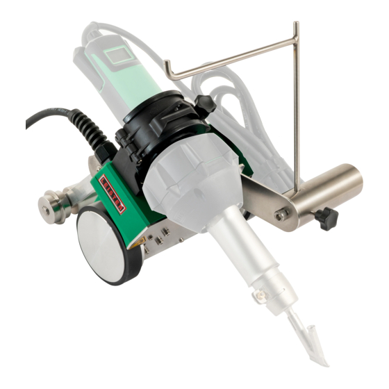
Verfügung aufbewahren. Leister MINIFLOOR Drive unit Anwendung Antriebseinheit für das Verschweissen von Fussböden mit optional erhältlichem Leister Heissluft-Handgerät. Warnung Lebensgefahr beim Öffnen des Gerätes, da spannungsführende Komponen- ten und Anschlüsse freigelegt werden. Vor dem Öffnen des Gerätes Netzstecker aus der Steckdose ziehen. -
Page 4: Technische Daten
Konformität Leister Technologies AG, Galileo-Strasse 10, CH-6056 Kaegiswil/Schweiz bestätigt, dass dieses Produkt in der von uns in Verkehr gebrachten Ausführung die Anforderungen der folgenden EU-Richtlinien erfüllt. Richtlinien: 2006/42 2004/108 (bis 19.04.2016), 2014/30 (ab 20.04.2016) 2006/95 (bis 19.04.2016), 2014/35 (ab 20.04.2016) - Page 5 Gerätebeschreibung 1. Netzanschlussleitung 16. Gummiring 2. Klemmschraube 17. Klemmvorrichtung Heissluft-Handgerät 3. Führungsrad 18. Öse für Schweissdraht 4. Führungsarm 19. Steckdose Heissluft-Handgerät 5. Traggriff 20. Arretierung Führungsarm 6. Hauptschalter 21. Einstellscheibe Anfahrschalter 7. Potentiometer Antrieb 22. Klettband 8. Öffnungen für Kabelbefestigung 9.
- Page 6 Transport Handgriff der Transportbox nicht Keine brennbaren Materialien in der für den Transport mit dem Kran ver- Transportbox lagern. wenden. Für den Transport muss das Heiss- Gerät darf nicht am Zusatzgewicht/ luft-Handgerät abgekühlt sein. Abschlussgewicht oder der Abroll- vorrichtung angehoben werden. Verlängerungskabel •...
- Page 7 105.432 für Drahtdurchmesser 3 mm, aufstecken (auf korrekte Ausrichtung von Rohrdüse und Schnellschweissdüse achten). Heissluft-Handgerät (23) an der Steckdose des MINIFLOOR (19) an- schliessen. Kabel des Heissluft-Handgerät (23) aufrollen und an den entspre- chenden Öffnungen (8) der Ab- deckplatte (14) mit Klettband (22)
- Page 8 Betriebsbereitschaft Abrollvorrichtung (11) in Bohrung (10) stecken und mit Klemmschraube (12) fixieren. Alternative ohne Abrollvorrichtung, Schweissdraht durch Öse (18) führen. H. Position der Einstellscheibe für An- fahrschalter (21) kontrollieren. Bedeutung: • Startverzögerung reduzieren (−) • Start verzögern (+) I. Heissluft-Handgerät (23), Schnell- schweissdüse (25) und Führungsrad (3) auf Schweissnut ausrichten.
- Page 9 Beschädigung überprüfen. Nur Verlängerungskabel mit Schutzleiter verwenden. Der MINIFLOOR darf nicht in explosionsgefährdeter bzw. entzündbarer Umgebung einge- setzt werden. Auf sicheren Stand bei der Arbeit achten. Netzanschlussleitung (1) muss frei beweglich sein und darf den Anwender oder Dritte bei der Arbeit nicht behindern.
-
Page 10: Starten Des Gerätes
Starten des Gerätes Vor Inbetriebnahme Netzanschlussleitung (1) und Stecker sowie Verlängerungskabel auf elektrische und mechanische Beschädigung überprüfen. Hauptschalter MINIFLOOR (6) und Hauptschalter Heissluft-Handgerät (23) ausschalten. Nennspannung, die auf den Geräten angegeben ist, muss mit der Netzspannung übereinstimmen. Gerät an Nennspannung anschliessen. - Page 11 Schweissablauf • Ohne Abrollvorrichtung Schweissdraht Ohne Abrollvorrichtung durch Öse (18) führen. Ende Schweissung • Nach der Schweissung Heissluft-Hand- gerät (23) auf Parkposition schwenken. • Antriebsmotor stoppt automatisch.
-
Page 12: Ausschalten Des Gerätes
• Schnellschweissdüse (25) mit Messingbürste reinigen. • Netzanschlussleitung (1) und Stecker auf elektrische und mechanische Beschädigung überprüfen. Störungen • Bei blockierten Antriebsrädern Hauptschalter des Heissluft-Handgerät (23) und des MINIFLOOR (6) aus- schalten. Wartung • Regelmässig kontrollieren, ob die Antriebsrollen frei drehen können. - Page 13 Leister MINIFLOOR Drive unit Application Drive unit for welding floors with optional Leister hot air hand tool. Warning Danger to life when opening the device as live components and connections are then exposed. Pull the mains plug from the outlet before opening the device.
-
Page 14: Technical Data
Conformity Leister Technologies AG, Galileo-Strasse 10, 6056 Kaegiswil, Switzerland confirms that this product fulfills the requirements of the following EU Guidelines in the models that we have made available for purchase. Guidelines: 2006/42 2004/108 (until 04/19/2016), 2014/30 (from 04/20/2016) 2006/95 (until 04/19/2016), 2014/35 (from 04/20/2016) -
Page 15: Device Description
Device description 1. Power supply cord 16. Rubber band 2. Clamping screw 17. Hot air hand tool clamping device 3. Guide wheel 18. Lug for welding rod 4. Guide arm 19. Hot air hand tool outlet 5. Carrying handle 20. Guide arm lock 6. -
Page 16: Extension Cable
Transport Do not use the handle on the trans- Do not store any flammable materi- port box for transport with the crane. als in the transport box. The hot air hand tool must be cooled Device is not permitted to be raised down for transport. - Page 17 Connect the hot air hand tool (23) to the outlet on the MINIFLOOR (19). Roll up the cable for the hot air hand tool (23) and attach to the appropriate openings (8) on the cover plate (14) with a hook-and- loop fastener (22).
- Page 18 Operating readiness Insert the unwinding device (11) into the hole (10) and fasten it in place with the clamping screw (12). Alternatively, without the unwinding de- vice, guide the welding rod through the lug (18). H. Inspect the position of the adjusting screw for the starting switch (21).
-
Page 19: Parameter Settings
Use extension cables with protective conductors only! The MINIFLOOR must not be used in areas with explosion and/or ignition hazards. Ensure a stable position during work. The power supply cord (1) must be able to move freely and must not hinder the user or third parties while working. -
Page 20: Starting The Device
Prior to commissioning, check the power supply cord (1), the plug, and the extension cable for electrical and mechanical damage. Switch off the MINIFLOOR (6) and hot air hand tool (23) main switches. The nominal voltage, specified on the devices must match the mains voltage. Connect the device to the nominal voltage. - Page 21 Welding Sequence • Without the unwinding device, guide the Without unwinding device welding rod through the lug (18). End of the welding process • Once the welding process is complete, swivel the hot air hand tool (23) into the parking position. •...
-
Page 22: Service And Repair
• Check the power supply cord (1) and plug for electrical and mechanical damage. Faults • If drive wheels are blocked, switch off the main switch of the hot air hand tool (23) and the MINIFLOOR (6). Maintenance • Regularly inspect if the drive wheels can turn freely. -
Page 23: Notice D'utilisation
Unité de commande Leister MINIFLOOR Application Unité de commande pour le soudage des revêtements de sol avec une soufflerie à air chaud manuelle Leister proposé en option. Avertissement Danger de mort en cas d’ouverture de l’appareil, en raison de l’exposition de composants et de connexions sous tension. -
Page 24: Caractéristiques Techniques
Conformité Leister Technologies AG, Galileo-Strasse 10, CH-6056 Kaegiswil/Suisse déclare que ce produit, dans les configurations mises en circulation, satisfait les exigences des directives européennes ci-après. Directives : 2006/42 2004/108 (jusqu'au 19/04/2016), 2014/30 (à partir du 20/04/2016) 2006/95 (jusqu’au 19/04/2016), 2014/35 (à partir du 20/04/2016) 2011 / 65 Normes harmonisées :... -
Page 25: Description De L'appareil
Description de l’appareil 1. Câble d’alimentation secteur 16. Anneau caoutchouté 2. Vis de blocage 17. Dispositif de serrage soufflerie à air chaud 3. Roue de guidage 18. Œillet pour fil à souder 4. Bras de guidage 19. Prise électrique soufflerie à air chaud 5. -
Page 26: Préparation Pour Le Fonctionnement
Transport Ne pas utiliser la poignée de la mal- Ne pas ranger de matériaux inflam- lette de transport pour un transport à mables dans la mallette de transport. l'aide d'une grue. La soufflerie à air chaud manuelle doit Ne pas soulever l'appareil au niveau être refroidie pour le transport . - Page 27 Préparation pour le fonctionnement B. Placer la soufflerie à air chaud ma- nuelle (23) dans le dispositif de serrage (17) et bien serrer avec la vis de blocage (2). La soufflerie à air chaud manuelle (23) doit arriver au niveau du dispositif de serrage (17).
- Page 28 Préparation pour le fonctionnement Insérer le dispositif dérouleur (11) dans l'alésage (10) et le fixer avec la vis de blocage (12). Alternative sans dispositif dérouleur, gui- der le fil à souder par l'œillet (18). H. Vérifier la position de la molette de réglage du starter (21).
-
Page 29: Réglage Des Paramètres
électrique ou mécanique. N'utiliser que des rallonges avec conducteur de protection. La commande MINIFLOOR ne doit pas être utilisée en environnement explosible ou inflammab- le. Veiller à une bonne stabilité pendant le travail. Le câble d'alimentation secteur (1) doit res- ter libre dans ses mouvements et ne doit entraver ni l'utilisateur, ni un tiers pendant le travail. -
Page 30: Démarrage De L'appareil
électrique ou mécanique. Couper la MINIFLOOR (6) et la soufflerie à air chaud (23) avec leur commutateur principal respectif. La tension nominale indiquée sur les appareils doit être identique à la tension du secteur. Connecter l’appareil à... - Page 31 Déroulement du soudage • En absence de dispositif dérouleur, guider Sans dispositif dérouleur le fil à souder par l'œillet (18). Fin de la soudure • La soudure terminée, reposer la souffle- rie à air chaud manuelle (23) en position d'arrêt. •...
- Page 32 • Laisser refroidir la soufflerie à air chaud manuelle (23). • Couper la soufflerie à air chaud manuelle (23) et la MINIFLOOR (6) avec leur commutateur principal respectif. • Nettoyer la buse de soudage rapide (25) avec une brosse en laiton.
-
Page 33: Instrucciones De Servicio
Dispositivo de guía Leister MINIFLOOR Aplicación Dispositivo de guía para soldadura sobre suelos con el dispositivo manual de aire caliente de Leister disponible de forma opcional. Advertencia Peligro de muerte al abrir el equipo, ya que podrá accederse a componentes y a conexiones conductores de tensión. -
Page 34: Datos Técnicos
Conformidad Leister Technologies AG, Galileo-Strasse 10, CH-6056 Kaegiswil/Suiza confirma que este producto cumple con los requisitos de las siguientes directivas UE en la versión comercializada por nosotros. Directivas: 2006/42 2004/108 (hasta el 19/04/2016), 2014/30 (a partir del 20/04/2016) 2006/95 (hasta el 19/04/2016), 2014/35 (a partir del 20/04/2016) -
Page 35: Descripción Del Equipo
Descripción del equipo 1. Cable de conexión de red 12. Tornillo de fijación para dispositivo desbobinador 2. Tornillo de fijación 13. Peso adicional 3. Rueda guía 14. Placa de cubierta 4. Brazo guía 15. Carcasa 5. Asa de transporte 16. Anillo de goma 6. - Page 36 Transporte No emplear el asa de la caja de No almacenar nunca materiales transporte para el transporte con grúa. inflamables en la caja de transporte. Para proceder al transporte, el dis- No debe elevar el dispositivo por el positivo manual de aire caliente debe peso adicional/peso final o por el estar frío.
- Page 37 Disposición de funcionamiento B. Coloque el dispositivo manual de aire caliente (23) en el soporte (17) y apriete con el tornillo de fijación (2). Asegurarse de que el dispositivo ma- nual de aire caliente (23) quede ali- neado al ras con el soporte (17). C.
- Page 38 Disposición de funcionamiento Insertar el dispositivo desbobinador (11) en el taladro (10) y sujetar el tor- nillo de fijación (12). Alternativa sin dispositivo desbobinador: pase el alambre de soldadura a través de la armella (18). H. Controle el disco de ajuste del inter- ruptor de arranque (21).
- Page 39 El MINIFLOOR no debe emplearse en entornos inflamables o con peligro de explosión. Ase- gurarse de contar con un apoyo firme durante el trabajo. El cable de conexión de red (1) tiene que poder moverse libremente y no debe molestar al usuario ni a terceros.
-
Page 40: Conexión Del Equipo
Antes de la puesta en marcha, revise el cable de conexión de red (1) y los conectores y cables de prolongación para descartar que tengan defectos mecánicos o eléctricos. Desconecte el interruptor principal de MINIFLOOR (6) y el interruptor principal del dispositivo manual (23). - Page 41 Proceso de soldadura • Sin dispositivo desbobinador: pase el Sin dispositivo desbobinador alambre de soldadura a través de la armella (18). Final soldadura • Después de la soldadura, gire el dispo- sitivo manual de aire caliente (23) a la posición de estacionamiento. •...
- Page 42 Desconexión del equipo • Deje enfriar el dispositivo manual de aire caliente (23). • Desconecte el interruptor principal del dispositivo manual de aire caliente (23) y del MINIFLOOR (6). • Limpie la boquilla de soldadura rápida (25) con un cepillo de latón.
-
Page 43: Istruzioni Per L'uso
Leister MINIFLOOR Unità motrice Applicazione Unità motrice per la saldatura di pavimenti, con apparecchio manuale ad aria calda Leister opzionale. Avvertenza Pericolo di morte in caso di apertura dell’apparecchio: contiene componenti e contatti sotto tensione non protetti. Prima di aprire l’apparecchio, estrarre sempre la spina dalla presa di corrente. -
Page 44: Specifiche Tecniche
Conformità Leister Technologies AG, Galileo-Strasse 10, CH-6056 Kägiswil/Svizzera certifica che il presente prodotto, nella versione immessa in commercio dall’azienda, soddisfa i requisiti delle direttive UE riportate di seguito. Direttive: 2006/42 2004/108 (fino al 19.04.2016), 2014/30 (dal 20.04.2016) 2006/95 (fino al 19.04.2016), 2014/35 (dal 20.04.2016) -
Page 45: Descrizione Dell'apparecchio
Descrizione dell’apparecchio 1. Cavo di alimentazione 16. Anello di gomma 2. Vite di fermo 17. Morsa di bloccaggio per apparecchio manuale ad aria calda 3. Ruota di guida 18. Occhiello per filo per saldatura 4. Braccio di guida 19. Presa di corrente per apparecchio manuale ad aria calda 5. - Page 46 Trasporto Non utilizzare la maniglia della Non conservare materiali infiamma- cassa di trasporto per il trasporto bili nella cassa di trasporto. con apparecchi di sollevamento. Per il trasporto è necessario che L’apparecchio non deve essere l’apparecchio manuale ad aria calda sollevato prendendolo dal peso sup- risulti completamente raffreddato.
- Page 47 Collegare l’apparecchio manuale ad aria calda (23) alla presa di corrente del prodotto MINIFLOOR (19). Arrotolare il cavo dell’apparecchio manuale ad aria calda (23) e fissarlo alle apposite asole (8) del pannello di copertura (14) serven- dosi della fascetta in velcro (22).
- Page 48 Operazioni preliminari all’esercizio Inserire il dispositivo di svolgimento (11) nell’apposito foro (10) e serrarlo in posizione con la vite di fermo (12). In alternativa, se non è presente alcun dispositivo di svolgimento, inserire il filo per saldatura attraverso l’apposito oc- chiello (18).
- Page 49 (1), alla spina e alla prolunga. Usare esclusivamente cavi di prolunga provvis- ti di messa a terra. È vietato utilizzare il prodotto MINIFLOOR in ambienti o aree a rischio di esplosione e/o in cui sia presente un rischio di infiammabilità. Durante le operazioni di lavoro accertarsi che l’apparecchio risulti perfettamente stabile.
- Page 50 Prima della messa in servizio, verificare l’assenza di danni meccanici e funzionali al cavo di alimentazione (1), alla spina e alla prolunga. Disinserire l’interruttore principale del prodotto MINIFLOOR (6) e l’interruttore principale dell’apparecchio manuale ad aria calda (23). La tensione nominale indicata sugli apparecchi deve corrispondere alla tensione di rete. Collegare l’apparecchio al valore di tensione nominale.
- Page 51 Esecuzione della saldatura • Se non è presente alcun dispositivo di Senza dispositivo di svolgimento svolgimento, inserire il filo per saldatura attraverso l’apposito occhiello (18). Fine della saldatura • Al termine delle operazioni di saldatura, posizionare l’apparecchio manuale ad aria calda (23) in posizione di staziona- mento.
- Page 52 • Verificare regolarmente che le ruote motrici siano in grado di muoversi liberamente. Assistenza e riparazioni • Le riparazioni devono essere eseguite esclusivamente dai centri di assistenza autorizzati da Leister. • Questi ultimi assicurano riparazioni sicure e affidabili in 24 ore, con parti di ricambio originali come da schemi elettrici ed elenchi parti di ricambio.
- Page 53 Leister MINIFLOOR Drive unit Toepassing Aandrijfeenheid voor het lassen van vloeren met optioneel verkrijgbaar hetelucht-apparaat van Leister. Waarschuwing Er is sprake van levensgevaar als u het lasapparaat opent, omdat dan com- ponenten en aansluitingen komen bloot te liggen die onder elektrische spanning kunnen staan.
-
Page 54: Technische Gegevens
Conformiteit Leister Technologies AG, Galileo-Strasse 10, CH-6056 Kägiswil (Zwitserland) bevestigt dat dit product in de door ons in het handelsverkeer gebrachte uitvoering in overeenstemming is met de onderstaande EG-richtlijnen. Richtlijnen: 2006/42 2004/108 (tot 19.04.2016), 2014/30 (vanaf 20.04.2016) 2006/95 (tot 19.04.2016), 2014/35 (vanaf 20.04.2016) - Page 55 Beschrijving van het lasapparaat 1. Kabel voor aansluiting op de netspanning 16. Rubberen ring 2. Klemschroef 17. Kleminrichting hetelucht-apparaat 3. Geleidewiel 18. Oogje voor het lasdraad 4. Geleidearm 19. Stopcontact voor het hetelucht-apparaat 5. Draaggreep 20. Vergrendeling voor de geleidearm 6.
- Page 56 Transport Gebruik de draaggreep van de trans- Bewaar geen brandbare materialen portkist niet voor het transporteren van in de transportkist. het apparaat met behulp van een kraan. Het apparaat mag niet aan het Alvorens het transport moet het hete- aanvullend gewicht/eindgewicht of lucht-apparaat afgekoeld zijn.
- Page 57 3 mm, vastma- ken (Let u op het correct afstellen van het buismondstuk en snellasmondstuk). Het hetelucht-apparaat (23) op de stopcontact van de MINIFLOOR (19) aansluiten. De kabel van hetHetelucht-appa- raat (23) oprollen en aan de bij-...
- Page 58 Gereedheid voor gebruik De afroller (11) in de bootgaten (10) steken en met klemschroeven(12) vastmaken. Alternatief zonder afroller, lasdraad door de ogen (18) leiden. H. De positie van de instelpoort voor de startschakelaar (21) controleren. Betekenis: • Startvertraging reduceren (−) •...
- Page 59 Gebruik uitsluitend een verlengkabel als die van een aardleider is voorzien! U mag de MINIFLOOR niet gebruiken in een explosiegevaarlijke of ontvlambare omgeving. Let er tijdens het lassen erop dat u en het lasapparaat stabiel staan. De netaansluitkabel (1) moet vrij kunnen bewegen en mag de gebruiker noch een derde tijdens de werkzaamheden niet hinderen.
- Page 60 Inspecteer of de netaansluitkabel (1), de stekker en de verlengkabel geen elektrische en/of mechanische beschadigingen vertonen. De hoofdschakelaar van de MINIFLOOR (6) en de hoofdschakelaar van het Hetelucht-apparaat (23) uitschakelen. De nominale bedrijfsspanning, zoals vermeld op het apparaat, moet overeenstemmen met de hoogte van de netspanning.
- Page 61 Het lasproces • Zonder de afroller moet het lasdraad door Zonder afroller de ogen (18) worden geleid. Einde van het lassen • Na het lassen het hetelucht-apparaat (23) in de parkeerstand zetten. • De aandrijfmotor stopt automatisch.
- Page 62 • U moet regelmatig controleren of de aandrijfrollen vrij kunnen draaien. Onderhoud en herstel • Laat herstellingen en reparaties uitsluitend uitvoeren door onderhoudsbedrijven die daartoe door Leister werden geautoriseerd. • Deze zorgen binnen 24 uur voor deskundig en betrouwbaar herstel of reparatie en gebruiken daarbij originele vervangende onderdelen conform de schakelschema's en de lijsten met vervangende onderdelen.
- Page 68 −...
- Page 73 取扱説明書 (メーカー取扱説明書) 使用開始前にこの取扱説明書をよくお読みになり、必要な時にい つでも読めるよう保管しておいてください。 ライスター ミニフロア ドライブユニット 用途 ライスター製ハンド熱風機 (オプション) 使用時の、床面溶接用ドライブユニット 警告 通電している構成部品および接続部が露出するため、装置を開 く際に生命の危険あり。必ず装置の電源を抜いてから装置を開 けてください。 火災および爆発の恐れあり。 特に可燃素材の付近や爆発性ガスの付 近では、ホットウェッジ装置の取り扱いを誤ると (素材の過熱など) 大変危険です。 火傷の危険!熱くなっている金属部分を手で触ないでください。装 置は必ず冷ましてください。熱風を人または動物に向けないでくだ さい。 機器は 保護接地線 を付けてコンセントに接続してください。装置の内外で線が遮断 されると大変危険です! 延長ケーブルには必ず保護接地線を使用してください! 挟まれる危険あり !指や毛髪、衣服などが挟まれる恐れがありま す。 注意 装置記載の定格電圧は、 電源電圧と一致していなくてはなりませ ん。 電源電圧が遮断された場合は、必ずメインスイッチと駆動装置 をオフにしてください。 作業員の安全を守るためにも、 工事現場で機器を使用する際は、 必ず配線用遮断器を用いてください。 装置からは決して目を離さずに使用してください。目の届かない 場所で、熱が可燃性の素材に達する可能性があります。 装置の取り扱いは専門の作業員が自ら行うか、当該作業員の監視 なしに行うことはできません。子どもには決して手を触れさせ...
- Page 74 適合性 ライスターテクノロジーズ社 (Leister Technologies AG, Galileo-Strasse 10, CH-6056 Kae- giswil/Switzerland) は、販売品として出荷されている本製品の仕様がEU指令に適合してい ることを認めます。 対象となる指令: 2006/42 2004/108 (2016年4月19日まで)、2014/30 (2016年4月20日以降) 2006/95 (2016年4月19日まで)、2014/35 (2016年4月20日以降) 2011/65 整合規格: E N 12100、EN 55014-1、EN 55014-2、EN 61000-6-2、EN 61000-3-2、 EN 61000-3-3、EN 62233、EN 60335-2-45、EN 50581 Kaegiswil, 2015/12/02 Bruno von Wyl, CTO Andreas Kathriner, GM (ブルーノ・フォン・ウィル、 (アンドレアス・カトリンガー、 最高技術責任者) 統括マネージャー) 廃棄について 電気工具、アクセサリー、梱包材は、環境に配慮し必ず分別の上リサイクルし てください。EU 諸国において、...
- Page 75 各部の名称 1. 電源ケーブル 16. ゴムリング 2. クランプねじ 17. ハンド熱風機のクランプ装置 3. ガイドホイール 18. 溶接ワイヤー用アイ 4. ガイドアーム 19. ハンド熱風機のソケッ ト 5. 運搬用ハンドル 20. ガイドアームのロック 6. メインスイッチ 21. 始動スイッチの調節ディスク 7. ドライブのポテンショメータ 22. 面ファスナー 8. ケーブル固定穴 9. キャスター 別売アクセサリー (供給品には含まれていません) : 10. リール挿入穴 23. ハンド熱風機 11. ...
- Page 76 輸送 クレーンでの運搬に、持ち運び 持ち運び用ケースには可燃物を 用ケースの持ち手を使用しない 保管しないでください。 でください。 輸送の際には、必ずハンド熱風 追加錘/錘一式、またはリール 機を冷ましておいてください。 部分を使って装置本体を吊上げ ることは、絶対にお止めくだ さい。 延長ケーブル • 延長ケーブルを使用する際には、必ず最小断面積を確認してください。 • 延長ケーブルの配線は必ず設置場所 (屋外など) の条件に合わせ、適宜目印を付けてくだ さい。 • 電源装置を使用する場合は、定格出力を守ってください。 2 × ハンド熱風機の定格出力、かつ配線用遮断器を装備。 • 装置は必ず接地してください。 作業の前に A. ハンド熱風機 (23) の直径に合っ たゴムリング (16) を、クランプ 装置 (17)にはめます。 品番 ハンドルの直径 Ø (mm) ゴムリング (16) 供給品 品番 155.153 57〜59 別売品 品番 154.723 64〜65 セットのリング各 155.153 & 154.723 60〜63...
- Page 77 作業の前に B. ハンド熱風機 (23) をクランプ装 置 (17)にセットし、クランプね じ (2) で固定します。 この時、ハンド熱風機 (23) がク ランプ装置 (17) とぴったり付く ようにしてください。 C. 5 mm パイプ ノズル (24)、 100.303 と、ワイヤー直径 4 mm のスピード溶接ノズル (25) 、 105.433 もしくは 3 mm の場 合は 105.432 を差し込みます ( パイプノズルとスピード溶接ノ ズルの装着位置を誤らないよう に注意してください)。 D. ハンド熱風機 (23) をミニフロ ア (19) のソケットに差し込みま...
- Page 78 作業の前に F. リール (11) を穴 (10) に差し込 み、クランプねじ (12) で固定し ます。 G. リ ー ル を 付 け な い 場 合 は 、 溶 接ワイヤーをアイ (18)に通しま す。 H. 始動スイッチ (21) の調節ディスク をチェックします。 操作方法: • 始動遅れを短縮する (−) • 始動を遅らせる (+) I. ハンド熱風機 (23)、 スピード溶接 ノズル (25)、ガイドホイール (3) を溶接溝に合わせます。...
- Page 79 パラメータ設定 ミニフロアの溶接速度をポテンシ ョメータ (7) で設定します。 溶接温度、およびオプションのハ ンド熱風機 (23) の風量を設定しま す。 ハンド熱風機 (23) を設定する際 は、使用する装置の取扱説明書に 従ってください。 レベル m/分 ft/分 10.1 11.5 13.1 14.1 使用環境/安全に関する注意事項 機器は屋外、またはよく換気された室内での使用に限られます。溶着中に材料が燃焼しな いよう、注意してください。 メーカーの製品安全データシート (MSDS) を順守してください。 装置を起動する前に電源ケーブル (1)、 プラグ、延長ケーブルを点検し、電気 的・機械的不具合が無いかどうか確認してください。延長ケーブルには必ず保 護接地線を使用してください。 爆発性雰囲気や発火の恐れがある場所で、ミニフロアを使用することを禁じま す。作業中は常に、安全に十分配慮してください。電源ケーブル (1) は自由に 動かせる状態にして、作業中も使用者や第三者の妨げにならないようにしてく ださい。 ミニフロアは安定した耐火性の土台 の上に置き、可燃物や爆発性ガスか ら十分に距離を置いてください。 作業を中断する時やハンド熱風機 (23) を冷ます時は、本体を傾けた 「パークポジション」にしてくだ さい (下図参照)。本機を移動する 際は、十分に冷ますとともにメイ...
- Page 80 装置の開始 装置を起動する前に電源ケーブル (1)、 プラグ、延長ケーブルを点検し、電気 的・機械的不具合が無いかどうか確認してください。 ミニフロア (6) のメインスイッチとハンド熱風機 (23) のメインスイッチは切っ てください。 機器に指定されている定格電圧は、 供給電圧に適応していなければなりません。 装 置を定格電圧に接続します。 停電時にはハンド熱風機 (23) を傾けて、 パークポジションにしてください。 熱風を人または動物に向けないでください。 ミニフロアを溶接する床に置き、 ハンド熱風機 (23) をパークポジシ ョンにします。ガイドアームのロ ック (20) を外します。 ガイドホイール (3) と溶接ワイヤー の溝とを合わせます。ミニフロア のメインスイッチ (6) をオンにしま す。 ハンド熱風機 (23) のスイッチを入 れます。 ヒーターの溶接とブロワー (装備し ている場合) の設定を行います。 ハンド熱風機を設定する際は、使 用する装置の取扱説明書に従って ください。 溶接の流れ 準備 材料メーカーの指示および現地の規定に従って、...
- Page 81 溶接の流れ • リールを付けない場合は、溶接 リールなし ワイヤーをアイ (18)に通します。 溶接の終了 • 溶接作業が終わったら、 ハンド 熱風機 (23) をパークポジション にします。 • ドライブモーターが自動的に停 止します。...
- Page 82 装置の停止 • ハンド熱風機 (23) を冷まします。 • ハンド熱風機 (23) とミニフロア (6) のメインスイッチ を切ります。 • 溶接ノズル (25) を真ちゅうブラシで清掃します。 • 電源ケーブル (1) とプラグに通電不良や機械的な損傷がないことを確認します。 障害物がある場合 • 駆動輪が遮られると、ハンド熱風機 (23) とミニフロア (6) のメインスイッチがオフになりま す。 メンテナンス • 駆動ローラーの回転が遮られていないか、定期的に検査してください。 サービスと修理 • 修理は必ず、当社認定のライスターサービス代理店にお任せください。 • 正規サービス代理店では 24 時間以内に、専門作業員が回路図とスペア部品リストに基づ く純正部品を使用し、確実な修理を行います。 保証 • 本機器については、 販売パートナー/セールスが直接保証した保証または保証権が、 購入日以 降適用されます。 保証または保証サービスを請求なさる場合には (領収書または納品書等の 証明書が必要) 、 製造ミスまたは加工ミスが販売パートナーにより交換品をお届けするか、 ま たは修理するなどで処理されます。 電気式ホッ トウェッジは保証の対象外となります。 • その他の保証または保証サービスについては、 義務的な法律の枠内で決定されています。 • ...
- Page 84 ® © Copyright by Leister Your authorised Service Centre is: Leister Technologies AG Galileo-Strasse 10 CH-6056 Kaegiswil/Switzerland Tel. +41-41662 74 74 +41-41662 74 16 www.leister.com sales@leister.com...
Need help?
Do you have a question about the MINIFLOOR and is the answer not in the manual?
Questions and answers