Olimpia splendid OS-CEBSH24EI Instructions For Installation, Use And Maintenance Manual
Hide thumbs
Also See for OS-CEBSH24EI:
Table of Contents
Advertisement
Available languages
Available languages
Quick Links
Advertisement
Chapters
Table of Contents

Related Manuals for Olimpia splendid OS-CEBSH24EI


Summary of Contents for Olimpia splendid OS-CEBSH24EI
- Page 1 ISTRUZIONI PER INSTALLAZIONE, USO E MANUTENZIONE INSTRUCTIONS FOR INSTALLATION, USE AND MAINTENANCE INSTRUCTIONS POUR L'INSTALLATION, L’EMPLOI ET L'ENTRETIEN HANDBUCH FÜR INSTALLATION, GEBRAUCH UND WARTUNG...
- Page 4 > 30 cm > 60 c m > 60cm > 30cm > 15 cm > 30 cm...
- Page 5 ODT °C ODT °C...
- Page 7 U.I. SMALL U.I. BIG Vmax Vmax Vmed Vmed Vmin Vmin 1000 1500 2000 2500 3000 3500 1000 1500 2000 2500 3000 3500...
- Page 9 OS-CEBSH24EI OS-CEBCH36EI OS-CEBCH48EI OS-CEBTH48EI OS-CEBCH60EI OS-CEBTH60EI V/ph/Hz 220-240/1/50 220-240/1/50 220-240/1/50 380-415/3+N/50 220-240/1/50 380-415/3+N/50 13,5 8,15 11,5 U.I.SHERPA SMALL U.I.SHERPA BIG V/ph/Hz 220-240/1/50 220-240/1/50 3,22 6,22 14,1 27,2...
- Page 10 Led A Led 4 Led 1 Led 5 Led 2 Led 6 Led 3 Key 1 Key 3 Key 5 Key 7 Key 7 Led B Led 7 Led 8 Led 9 Key 2 Key 4 Key 6 - 15 ODT °...
-
Page 12: Table Of Contents
GENERALITÁ INFORMAZIONI GENERALI SIMBOLOGIA 1.2.1 Pittogrammi redazionali 1.2.2 Pittogrammi relativi alla sicurezza AVVERTENZE REGOLE FONDAMENTALI DI SICUREZZA RICEVIMENTO E DISIMBALLO UNITÀ ESTERNA UNITÀ INTERNA ELENCO DEI COMPONENTI PRINCIPALI UNITÀ INTERNA ELENCO COMPONENTI A CORREDO UNITÀ INTERNA E DESCRIZIONI DELLE PARTI INSTALLAZIONE INSTALLAZIONE DELL’UNITÀ... -
Page 13: Generalitá
Le pompe di calore aria-acqua NON DEVONO essere installate in ambienti con presenza di gas in ammabili, gas esplosivi, in ambienti molto umidi (lavanderie, serre, ecc.), o in locali dove sono presenti altri macc inari c e generano una forte fonte di calore. In caso di sostituzione di componenti utilizzare esclusivamente ricambi originali OLIMPIA SPLENDID. -
Page 14: Simbologia
IMPORTANTE! Per prevenire ogni risc io di folgorazione è indispensabile staccare gli interruttori generali prima di effettuare collegamenti elettrici ed ogni operazione di manutenzione sugli apparecc i. Rendere note a tutto il personale interessato al trasporto ed all’installazione della macc ina le presenti istruzioni. SMALTIMENTO Il simbolo sul prodotto o sulla confezione indica che il prodotto non deve essere considerato come un normale ri uto domestico, ma deve essere portato nel punto di raccolta appropriato per il riciclaggio di apparecchiature elettriche ed elettroniche. -
Page 15: Regole Fondamentali Di Sicurezza
• L’installazione degli apparecchi OLIMPIA SPLENDID deve essere effettuata da impresa abilitata che a ne lavoro rilasci al responsabile dell’impianto una dichiarazione di conformità in ottemperanza alle Norme vigenti ed alle indicazioni fornite dalla OLIMPIA SPLENDID nel presente libretto. •... -
Page 16: Unità Esterna
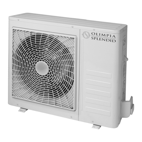
UNITÀ ESTERNA ( g. 1) L’unità esterna ( g. 1) è disponibile in sei modelli OS-CEBSH24EI OS-CEBCH36EI OS-CEBCH48EI OS-CEBTH48EI OS-CEBCH60EI OS-CEBTH60EI Larghezza mm Profondità mm Altezza mm 1245 1245 1245 1245 Peso kg UNITÀ INTERNA ( g. 2) L’unità interna ( g. 2) è disponibile in quattro modelli. -
Page 17: Installazione Dell'unità Interna
La mancata applicazione delle norme indicate, che può causare mal funzionamento delle apparecchiature, sollevano la ditta OLIMPIA SPLENDID da ogni forma di garanzia e da eventuali danni causati a persone, animali o cose. È importante che l’impianto elettrico sia eseguito secondo le norme vigenti, rispetti i dati riportati nel capitolo Caratteristiche tecniche e sia costituito da una corretta messa a terra. -
Page 18: Limiti Di Funzionamento
A corredo dell’unità esterna viene fornita una rete di copertura della batteria di scambio termico; questa è prevista per installazioni accessibili al pubblico. Il montaggio della rete potrebbe causare, in caso di elevata umidità a bassa temperatura (nebbia) o neve, l’accumulo di g iaccio sulla batteria con riduzione delle prestazioni del sistema. LIMITI DI FUNZIONAMENTO ( g.10) I diagrammi di g.10 de niscono i limiti di temperatura dell’acqua (LWT) e dell’aria esterna (ODT) in cui la pompa di calore può... -
Page 19: Prove E Veri Che
2.4.1 Prove e veri c e ( gg. 14-15) Ultimati i collegamenti dei tubi occorre eseguire una veri ca sulla perfetta tenuta dell’impianto frigorifero. Per eseguire le operazioni di seguito descritte è necessario utilizzare un gruppo manometrico speci co per R410A ed una pompa del vuoto con portata minima di 40 l/min: Svitare il tappo di chiusura del raccordo di servizio della linea del gas ( g. -
Page 20: Circuito Idraulico
Il diametro nominale minimo delle tubazioni idraulic e di collegamento deve essere di 1”. Per consentire le operazioni di manutenzione o riparazione è indispensabile c e ogni allacciamento idraulico sia dotato delle relative valvole di c iusura manuali. La tabella sottostante mostra le caratteristiche che deve avere l’impianto idraulico. OS-CEBSH24EI OS-CEBCH36EI OS-CEBCH48EI OS-CEBTH48EI... -
Page 21: Valori Di Riferimento Acqua Impianto
VALORI DI RIFERIMENTO ACQUA IMPIANTO • pH: 6,5 ÷ 7,8 • Conducibilità elettrica: compresa tra 250 e 800 S/cm • Durezza totale: compresa tra 5 e 20 °F • Ferro totale: minore di 0,2 ppm • Manganese: minore di 0,05 ppm •... -
Page 22: Accesso Al Quadro Elettrico
Le linee di alimentazione devono essere adeguatamente dimensionate per evitare cadute di tensione o il surriscaldamento di cavi o altri dispositivi posti sulle linee stesse. La linea di alimentazione dell’unità esterna deve essere sezionabile dalla rete elettrica mediante un interruttore magnetotermico adeguato all’assorbimento della macchina con relè... -
Page 23: Controlli Di Installazione
• morsetto 2 sc eda elettronica contatto pulito remoto modo riscaldamento/modo raffreddamento • morsetto 3 sc eda elettronica contatto pulito remoto modo Eco • morsetto 4 sc eda elettronica contatto pulito remoto modalità notturna • morsetto 5 sc eda elettronica contatto pulito remoto attivazione acqua sanitaria (già collegato a morsettiera 5/L) •... -
Page 24: Uso E Manutenzione
USO E MANUTENZIONE PANNELLO DI COMANDO DELL’UNITÀ INTERNA ( g. 27) Aprendo lo sportello sul pannello frontale si accede al manometro, al pannello di controllo ed all’interruttore generale. Sul pannello ( g. 27) sono presenti i seguenti dispositivi: A Manometro. Visualizza la pressione dell’impianto idraulico, consente di veri care la pressione dell’acqua all’interno del circuito. I valori devono essere compresi da 1 a 2 bar. -
Page 25: Menù Utente
• t4 temperatura sensore aria esterna • cS1 set point 1 in modo raffreddamento • cS2 set point 2 (Eco) in modo raffreddamento • CHC ore di funzionamento compressore • HS1 set point 1 in modo riscaldamento • HS2 set point 2 (Eco) in modo riscaldamento Per visualizzare le suddette temperature/set procedere nel seguente modo: •... - Page 26 Per l’impostazione dei parametri fare riferimento anche alla tabella sottostante riassuntiva dei parametri. Esempio: Premere ey4 , si visualizza USr sul display Premere ey6 , si visualizza il primo parametro hrS (impostazione ore dell’orologio) Premere ey6 , si visualizza il valore del parametro (es.:10) Premere ey6 per tre secondi, il valore del parametro lampeggia sul display Premere ey1...
-
Page 27: Attivazione E Funzioni Service
Parametro MNEMONICO MENU Campo di Impostazione COMMENTI DISPLAY regolazione di fabbrica SET POINT Temperature/ Luc 0: 20°C Luc 0: 25°C Impostazioni di fabbrica per RISCALDAMENTO 2 - 55°C Luc 1: 30°C pavimenti radianti (Eco Mode) Luc 1: 20°C Utente - 60°C SET POINT Temperature/ 20-55°C... - Page 28 • CONTROLLO REMOTO È possibile controllare alcune funzioni dell’apparecchio in modo remoto tramite dei contatti puliti. Le connessioni dei contatti vanno effettuati sulla morsettiera della scheda elettronica dell’unità interna ( g. 23) come sotto descritto: morsetto 1: accensione/spegnimento: con contatto pulito aperto il sistema è in stand by, con contatto chiuso il sistema è acceso morsetto 2: cambio modo di funzionamento riscaldamento/raffreddamento: con contatto pulito aperto il sistema è...
-
Page 29: Impostazione Dei Parametri Menù Service
La durata dell’azione è dettata dalle caratteristiche dell’impianto. Il batterio della Legionella reagisce in maniera diversa in funzione della temperatura massima raggiunta nel circuito e all’aumentare della temperatura diminuisce il tempo di durata. Il controllo segnala l’esecuzione della funzione Antilegionella mostrando sul display la scritta LEG ed esce dalla funzione dopo un tempo massimo di 5 ore se per qualche motivo la temperatura non è... - Page 30 Per l’impostazione dei parametri fare riferimento anche alla tabella riassuntiva dei parametri. Parametro MNEMONICO MENU Campo di Impostazione COMMENTI DISPLAY regolazione di fabbrica RESISTENZE Service 0,1,2 ELETTRICHE INTERNE ADDIZIONALI resistenze elettriche disattivate primo stadio resistenze elettriche attivato primo e secondo stadio resistenze elettriche attivato SENSORE DI Service...
- Page 31 Parametro MNEMONICO MENU Campo di Impostazione COMMENTI DISPLAY regolazione di fabbrica SOGLIA TEMPERATURA Service -15 a 20°C 2°C Se bc 1 e temperatura ARIA ESTERNA aria esterna t4<otE PER ATTIVAZIONE il contatto connesso RESISTENZE ai morsetti 14 e 15 ELETTRICHE viene chiuso.
- Page 32 Parametro MNEMONICO MENU Campo di Impostazione COMMENTI DISPLAY regolazione di fabbrica ISTERESI TEMPERATURA Service 5°C - 25°C 10°C Da usare solo quando SERBATOIO ACQUA dhU 2 (sensore t3 SANITARIA T3 nel serbatoio acqua sanitaria) CURVA CLIMATICA Service -15 – +50°C 20°C Impostazioni di fabbrica RAFFREDDAMENTO ARIA...
-
Page 33: Disattivazione E Spegnimento Per Lunghi Periodi
è tecnicamente abilitato e preparato e può inoltre disporre, se necessario, di ricambi originali. Il piano di manutenzione che il Servizio Tecnico di Assistenza OLIMPIA SPLENDID o il manutentore deve osservare, con periodicità annuale, prevede le seguenti operazioni e controlli: •... -
Page 34: Allarmi Display Unità Esterna
Allarme #4 Guasto sensore aria esterna Allarme #5 Protezione antigelo scambiatore a piastre Allarme #6 Allarme ussostato Allarme #7 Errore di comunicazione con l’unità esterna Allarme #8 Ciclo antilegionella non effettuato Allarme #9 Errore comunicazione porta seriale RS485 Allarme #10 Protezione di sovracorrente (allarme unità... - Page 36 GENERAL GENERAL INFORMATION S MBOLS 1.2.1 Editorial pictograms 1.2.2 Safety pictograms WARNINGS ESSENTIAL SAFET REGULATIONS RECEPTION AND UNPAC ING EXTERNAL UNIT INTERNAL UNIT LIST OF INTERNAL UNIT MAIN COMPONENTS LIST OF COMPONENTS PROVIDED AND DESCRIPTION OF PARTS INSTALLATION INTERNAL UNIT INSTALLATION 2.1.1 Opening the panels 2.1.2...
-
Page 37: General
(laundry rooms, green ouses etc.), or in rooms ere t ere are ot er mac ines generating a lot of eat. S ould components need replacing, al ays use OLIMPIA SPLENDID original spare parts. -
Page 38: S Mbols
IMPORTANT! To prevent any ris of electric s oc , t e master s itc es must be disconnected before ma ing electrical connections and carrying out maintenance on t e appliances. Ma e sure t at all personnel responsible for transport and installation of t e appliance are a are of t ese instructions. DISPOSAL The symbol on the product or on the packaging indicates that the product must not be considered as normal domestic refuse but it must be taken to an appropriate disposal point for recycling electrical and electronic appliances. -
Page 39: Essential Safet Regulations
• OLIMPIA SPLENDID appliances must be installed by an authorised installer who, on completion of the work, will release a declaration of conformity to the client in compliance with current regulations and with the indications given by OLIMPIA SPLENDID in this booklet. -
Page 40: External Unit
EXTERNAL UNIT ( g. 1) The external unit ( g. 1) is available in six models OS-CEBSH24EI OS-CEBCH36EI OS-CEBCH48EI OS-CEBTH48EI OS-CEBCH60EI OS-CEBTH60EI Width mm Depth mm Height mm 1245 1245 1245 1245 Weight kg INTERNAL UNIT ( g. 2) The internal unit ( g. 2) is available in four models. -
Page 41: Installation
Follow the instructions given in this manual closely in order to achieve a successful installation and optimum performance. Failure to apply the indicated regulations, which may cause the appliance to malfunction, relieves OLIMPIA SPLENDID of any form of warranty and of any damage caused to persons, animals or property. -
Page 42: Operating Limits
T e e ternal unit is supplied it a mes for covering t e eat e c ange battery; t is is envisaged for installations accessible to t e public. Fitting t e mes may cause, in t e event of ig umidity at lo temperature (fog) or sno , a build-up of ice on t e battery... -
Page 43: Tests And Checks
2.4.1 Tests and c ec s ( g. 14, 15) Once the pipes are connected, check the refrigerant circuit is perfectly sealed. To perform the operations described below, use a manometric unit speci c for R410A and a vacuum pump with minimum ow rate of 40 l/min: Unscrew the cap on the gas line union ( g. -
Page 44: Hydraulic Circuit
To allo t e maintenance and repair operations it is indispensable t at eac ydraulic connection is tted it respec- tive manual closing valves. The table below shows the characteristics the hydraulic system must have. OS-CEBSH24EI OS-CEBCH36EI OS-CEBCH48EI OS-CEBTH48EI OS-CEBCH60EI... -
Page 45: S Stem Water Reference Values
SYSTEM WATER REFERENCE VALUES • pH: 6.5 to 7.8 • Electric conductivity: between 250 and 800 μS/cm • Total hardness: between 5 and 20 °F • Total iron: below 0.2 ppm • Manganese: below 0.05 ppm • Chlorides: below 250 ppm •... -
Page 46: Access To Electrical Connections
The power lines must be suitably sized to prevent voltage drops or overheating of cables or other devices on the lines. The power line of the external unit must be capable of being sectioned from the mains using a thermomagnetic circuit breaker suitable for the machine input with differential relay, with maximum calibration equal to that stated in national electrical regulations (see table in g. -
Page 47: Installation Chec S
• terminal 2 electronic board heating/cooling mode remote free contact • terminal 3 electronic board Eco mode remote free contact • terminal 4 electronic board night-time mode remote free contact • terminal 5 electronic board domestic water activation remote free contact (already connected to terminal board 5/L) •... -
Page 48: Use And Maintenance
USE AND MAINTENANCE INTERNAL UNIT CONTROL PANEL ( g. 27) The pressure gauge, control panel and master switch are accessed by opening the front panel door. The panel ( g. 27) includes the following devices: A Pressure gauge. Displays the hydraulic system pressure, enables the water pressure inside the circuit to be checked. Values must be between 1 and 2 bar. -
Page 49: User Menu
• t4 outside air sensor temperature • cS1 set-point 1 in cooling mode • cS2 set-point 2 (Eco) in cooling mode • CHC compressor operating hours • HS1 set-point 1 in heating mode • HS2 set-point 2 (Eco) in heating mode To view the above temperatures/set-points, proceed as follows: •... - Page 50 To set the parameters see the table below that summarises the parameters. Example: Press ey4 , to view USr on the display Press ey6 , to view the rst parameter hrS (clock hour setting) Press ey6 , to view the parameter value (e.g.: 10) Press ey6 for three seconds, the parameter value ashes on the display Press ey1...
-
Page 51: Activation And Service Functions
Parameter DISPLAY MENU Range of Factory COMMENTS MNEMONIC ad ustment setting HEATING SET-POINT Temperature/ Luc 0: 20°C Luc 0: 25°C Factory settings for radiant 2 (Eco Mode) - 55°C Luc 1: 30°C oors Luc 1: 20°C User - 60°C DOMESTIC WATER Temperature/ 20-55°C 50°C... - Page 52 • REMOTE CONTROL Some appliance functions can be controlled remotely using free contacts. The contacts should be connected to the terminal board of the internal unit’s electronic board ( g. 23) as described below: terminal 1: on/off: with the free contact open the system is in stand-by, with the contact closed the system is on terminal 2: toggle heating/cooling operating mode: with the free contact open the system is in heating mode, with the contact closed the system is in cooling mode...
-
Page 53: Setting The Service Menu Parameters
The duration of the action is dictated by system characteristics. Legionella bacteria react differently depending on the maximum temperature reached in the circuit. The higher the temperature, the shorter the duration. The control signals the anti-legionella function is running by displaying LEG and exits the function after a maximum of 5 hours, if for some reason the temperature is not reached inside the tank. - Page 54 To set the parameters see the table that summarises the parameters. Parameter DISPLAY MENU Range of Factory COMMENTS MNEMONIC ad ustment setting ADDITIONAL INTERNAL Service 0,1,2 ELECTRICAL HEATER ELEMENTS electrical heater elements deactivated electrical heater elements rst stage activated electrical heater elements rst and second stage activated WATER TEMPERATURE...
- Page 55 Parameter DISPLAY MENU Range of Factory COMMENTS MNEMONIC ad ustment setting DOMESTIC WATER Service 0,1,2 If dhU 1 set the PRODUCTION external thermostat production disabled (free contact) to a production activated via temperature below free contact 60°C production activated via domestic water tank sensor ANTI-LEGIONELLA C CLE Service...
- Page 56 Parameter DISPLAY MENU Range of Factory COMMENTS MNEMONIC ad ustment setting COOLING CLIMATE Service -15 – +50°C 20°C Factory settings for CURVE FOR MAXIMUM fan coils and control of WATER TEMPERATURE systems with leaving water temperature OUTSIDE AIR COOLING Service Luc 0: 18°C (LUc 1)
-
Page 57: Deactivation And Shutdown For Prolonged Periods
Service Technician, who is technically authorised and trained, and will use original spare parts. The maintenance plan that the OLIMPIA SPLENDID service technician or the maintenance engineer must adhere to, on an annual basis, includes the following operations and checks: •... -
Page 58: Alarms On External Unit Display
Allarme #4 Outside air sensor faulty Allarme #5 Plate exchanger frost-protection Allarme #6 Flow switch alarm Allarme #7 Communication error with external unit Allarme #8 Anti-legionella cycle not performed Allarme #9 RS485 serial port communication error Allarme #10 Overcurrent protection (external unit alarm **) Allarme #11 Power voltage protection (external unit alarm **) Allarme #12... - Page 60 GENERALITES INFORMATIONS GENERALES S MBOLES 1.2.1 Pictogrammes rédactionnels 1.2.2 Pictogrammes relatifs à la sécurité AVERTISSEMENTS REGLES FONDAMENTALES DE SÉCURITÉ RECEPTION ET DEBALLAGE UNITÉ EXTERNE UNITÉ INTERNE LISTE DES COMPOSANTS PRINCIPAUX UNITE INTERNE LISTE COMPOSANTS FOURNIS ET DESCRIPTION DES PARTIES INSTALLATION INSTALLATION DE L’UNITÉ...
-
Page 61: Generalites
(buanderies, serres, etc.), ou dans des locau où se trouvent d’autres mac ines produisant une importante source de c aleur. En cas de remplacement de composants, utiliser e clusivement des pièces de rec ange originales OLIMPIA SPLENDID. -
Page 62: S Mboles
IMPORTANT! Pour pr venir tout risque d' lectrocution, il est indispensable de d sactiver l'interrupteur g n ral avant d'effectuer des branc ements lectriques ou des op rations d'entretien sur les appareils. Communiquer ces instructions à tout le personnel concern par le transport et l’installation de la mac ine. ELIMINATION Ce symbole apposé... -
Page 63: Regles Fondamentales De Sécurité
• L’installation des appareils OLIMPIA SPLENDID doit être effectuée par une entreprise habilitée qui, à la n des travaux, devra délivrer au responsable du circuit une déclaration de conformité selon les Dispositions en vigueur et les indications fournies par OLIMPIA SPLENDID dans le présent manuel. L’installation des appareils OLIMPIA SPLENDID doit être effectuée par une entreprise habilitée qui, en n de travail, doit remettre au responsable de l'équipement une déclaration de conformité... -
Page 64: Unité Externe
UNITÉ EXTERNE ( g. 1) L’unité externe ( g. 1) est disponible en six modèles OS-CEBSH24EI OS-CEBCH36EI OS-CEBCH48EI OS-CEBTH48EI OS-CEBCH60EI OS-CEBTH60EI Largeur mm Profondeur mm Hauteur mm 1245 1245 1245 1245 Poids kg UNITÉ INTERNE ( g. 2) L’unité interne ( g. 2) est disponible en quatre modèles. -
Page 65: Installation
Le non respect des dispositions indiquées, qui peut entraîner un mauvais fonctionnement des appareils, dégage la société OLIMPIA SPLENDID de toute forme de garantie et de toute responsabilité concernant les dommages causés à des personnes, des animaux ou des choses. -
Page 66: Limites De Fonctionnement
Avec l’unit e terne est fourni un treillis de couverture de la batterie d’ c ange t ermique; il est pr vu pour des installations accessibles au public. Le montage du treillis pourrait causer, en cas d’ umidit lev e à basse temp rature (brouillard) ou de neige, l’accumulation de glace sur la batterie avec r duction des performances du système. -
Page 67: Tests Et Contrôles
2.4.1 Tests et contr les ( gures 14-15) Une fois terminés les branchements des tubes, il faut effectuer un contrôle d’étanchéité parfaite du circuit frigori que. Pour effectuer les opérations décrites ci-après, il est nécessaire d’utiliser un groupe manomètre spéci que pour R410A et une pompe à... -
Page 68: Circuit Hydraulique
Pour permettre les op rations d'entretien ou de r paration, il est indispensable que c aque branc ement ydraulique soit dot des valves manuelles de fermeture correspondantes. Le tableau ci-dessous montre les caractéristiques que doit avoir le circuit hydraulique. OS-CEBSH24EI OS-CEBCH36EI OS-CEBCH48EI... -
Page 69: Valeurs De Référence Eau Circuit
VALEURS DE RÉFÉRENCE EAU CIRCUIT • pH : 6,5 ÷ 7,8 • Conductivité électrique : comprise entre 250 et 800 μS/cm • Dureté totale : comprise entre 5 et 20 °F • Fer total : inférieur à 0,2 ppm • Manganèse : inférieur à... -
Page 70: Accès Aux Connexions Électriques
Les lignes d’alimentation doivent être correctement dimensionnées pour éviter des chutes de tension ou la surchauffe de câbles ou d’autres dispositifs présents sur les lignes. La ligne d’alimentation de l’unité externe doit pouvoir être sectionnée du réseau électrique au moyen d’un interrupteur relais magnétothermique approprié... -
Page 71: Contrôles De Installation
• borne 2 carte lectronique contact propre distant mode chauffage/mode refroidissement • borne 3 carte lectronique contact propre distant mode Eco • borne 4 carte lectronique contact propre distant modalité nocturne • borne 5 carte lectronique contact propre distant activation eau sanitaire (déjà branché à la boîte à bornes 5/L) •... -
Page 72: Emploi Et Maintenance
EMPLOI ET MAINTENANCE PANNEAU DE COMMANDE DE L’UNITE INTERNE ( g. 27) En ouvrant le portillon sur le pupitre en façade on accède au manomètre, au pupitre de contrôle et à l’interrupteur général. Sur le panneau ( g. 27) sont présents les dispositifs suivants : A Manomètre. -
Page 73: Menu Utilisateur
• t4 température capteur air externe • cS1 set point 1 de mode refroidissement • cS2 set point 2 (Eco) de mode refroidissement • CHC heures de fonctionnement compresseur • HS1 set point 1 de mode chauffage • HS2 set point 2 (Eco) de mode chauffage Pour af cher les dites températures/set procéder de la façon suivante : •... - Page 74 Pour la con guration des paramètres se reporter également au tableau ci-dessous de récapitulation des paramètres. Exemple: Presser ey4 , on voit s’af cher USr sur le dispositif d’af chage Presser ey6 , on voit s’af cher le premier paramètre hrS (con guration heures de l’horloge) Presser ey6 , on voit s’af cher la valeur du paramètre (ex.
-
Page 75: Activation Et Fonctions Service
Paramètre MNEMONIQUE MENU C amp de Con guration COMMENTAIRES DISPOSITIF r glage d’usine D’AFFICHAGE SET POINT Températures/ Luc 0: 20°C Luc 0: 30°C Con gurations d’usine pour CHAUFFAGE 1 - 55°C Luc 1: 35°C sols rayonnants Luc 1: 20°C Utilisateur - 60°C SET POINT Températures/... - Page 76 • CONTRÔLE DISTANT Il est possible de contrôler certaines fonctions de l’appareil de façon distante au moyen de contacts propres. Les connexions des contacts doivent être effectuées sur la boîte à bornes de la carte électronique de l’unité interne ( g. 23) de la façon décrite ci-dessous : borne 1 : allumage/extinction: avec contact propre ouvert le système est en veille, avec contact fermé...
-
Page 77: Configuration Des Paramètres Menu Service
La durée de l’action est dictée par les caractéristiques de l’installation. La bactérie de la légionellose réagit différemment en fonction de la température maximum atteinte dans le circuit, la durée diminue proportionnellement à l’augmentation de la température. Le contrôle signale l’exécution de la fonction Anti-légionellose en indiquant sur le dispositif d’af chage la mention LEG et quitte la fonction après un temps maximum de 5 heures si, pour quelque motif que ce soit, la température n’est pas atteinte à... - Page 78 Pour la con guration des paramètres, se reporter également au tableau récapitulatif des paramètres. Paramètre MNEMONIQUE MENU C amp de Con guration COMMENTAIRES DISPOSITIF r glage d’usine D’AFFICHAGE RÉSISTANCES Service 0,1,2 ÉLECTRIQUES INTERNES SUPPLÉMENTAIRES résistances électriques désactivées premier stade résistances électriques activé...
- Page 79 Paramètre MNEMONIQUE MENU C amp de Con guration COMMENTAIRES DISPOSITIF r glage d’usine D’AFFICHAGE SEUIL TEMPÉRATURE Service -15 à 20°C 2°C Si bc 1 le contact sur AIR EXTERNE les bornes 14 et 15 POUR ACTIVATION de la boîte à bornes RÉSISTANCES unité...
- Page 80 Paramètre MNEMONIQUE MENU C amp de Con guration COMMENTAIRES DISPOSITIF r glage d’usine D’AFFICHAGE PERIODICITE ACTIVATION Service 0-20 minutes Quand le set point est POMPE QUAND LE SET satisfait (compresseur POINT Il EST SATISFAIT éteint): cPP 0: la pompe reste allumée cPP>0 la pompe est éteinte pendant cPP...
-
Page 81: Desactivation Et Extinction Pour Periodes Prolongees
Technique d’Assistance, qui est techniquement préparé et peut en outre disposer, si nécessaire, de pièces de rechange originales. Le plan de maintenance que le Service Technique d’Assistance OLIMPIA SPLENDID ou le technicien de maintenance doit respecter, selon une périodicité annuelle, prévoit les opérations et contrôles suivants : •... -
Page 82: Alarmes Dispositif D'af Chage Unité Externe
Alarme #4 Défaut capteur air externe Alarme #5 Protection antigel échangeur à plaques Alarme #6 Alarme ux-stat Alarme #7 Erreur de communication avec l’unité externe Alarme #8 Cycle anti-légionellose non effectué Alarme #9 Erreur communication port série RS485 Alarme #10 Protection de surintensité... - Page 84 ALLGEMEINES ALLGEMEINE INFORMATIONEN S MBOLGEBUNG 1.2.1 Redaktionelle Piktogramme 1.2.2 Piktogramme bezüglich der Sicherheit WARNHINWEISE GRUNDLEGENDE SICHERHEITSREGELN ERHALT UND AUSPAC EN AUSSENEINHEIT INNENEINHEIT LISTE DER HAUPT OMPONENTEN DER INNENEINHEIT VERZEICHNIS DER MITGELIEFERTEN OMPONENTEN UND BESCHREIBUNG DER TEILE INSTALLATION INSTALLATION DER INNENEINHEIT 2.1.1 Öffnung der Blenden 2.1.2...
-
Page 85: Allgemeines
Umgebungen (W sc ereien, Treib usern us .) oder in R umen, in denen sic eitere star e W rme abgebende Masc inen be nden, betrieben erden. Bei Aus ec selung von Komponenten ver enden Sie aussc lie lic Originalersatzteile von OLIMPIA SPLENDID. -
Page 86: S Mbolgebung
WICHTIG! Zur Vorbeugung eglic er Stromsc laggefa r ist unbedingt der Hauptsc alter abzustellen, bevor irgend elc e ele trisc en Ansc l sse ergestellt oder Wartungsarbeiten an den Ger ten durc gef erden. Mac en Sie diese An eisungen dem gesamten in den Transport und die Installation der Masc ine einbezogenen Personal be annt. -
Page 87: Grundlegende Sicherheitsregeln
• Die Installation der OLIMPIA SPLENDID Ger te ist durch eine Fach rma auszuführen, die bei Abschluss der Arbeiten dem Verantwortlichen der Anlage eine Erkl rung zur onformit t mit den geltenden Vorschriften und den von OLIMPIA SPLENDID in diesem Handbuch festgesetzten Anweisungen übergibt. -
Page 88: Ausseneinheit
AUSSENEINHEIT (Abb. 1) Die Außeneinheit (Abb. 1) ist in sechs Modellen erh ltlich. OS-CEBSH24EI OS-CEBCH36EI OS-CEBCH48EI OS-CEBTH48EI OS-CEBCH60EI OS-CEBTH60EI Breite mm Tiefe mm Höhe mm 1245 1245 1245 1245 Gewicht kg INNENEINHEIT (Abb. 2) Die Inneneinheit (Abb. 2) ist in vier Modellen erh ltlich. -
Page 89: Installation
Die nicht erfolgte Anwendung der angegebenen Vorschriften kann Betriebsstörungen an den Ger ten verursachen und entbindet die Firma OLIMPIA SPLENDID aus jeder Form der Gew hrleistungsp icht sowie der Haftung für eventuelle Sch den an Personen, Tieren oder Gegenst nden. -
Page 90: Betriebsgrenzen
Zum Lieferumgang der Au enein eit ge rt ein Abdecknetz f r die W rme bertragungsbatterie. Diese Vorric tung ist f r ffentlic zug nglic e Installationen vorgese en. Die Montage des Netzes k nnte im Fall o er Luftfeuc tigkeit bei niedrigen Temperaturen (Nebel) oder Sc nee die Ansammlung von Eis unter der Batterie mit Anna me der Systemleistungen verursac en. -
Page 91: Prüfungen Und Ontrollen
2.4.1 Pr fungen und Kontrollen (Abb. 14-15) Nach Fertigstellung der Rohrverbindungen ist eine berprüfung der einwandfreien Dichtigkeit der ühlanlage durchzuführen. Zur Durchführung der nachstehend beschriebenen Arbeitsschritte ist die Verwendung einer spezi schen Manometer-Gruppe für R410A sowie einer Vakuumpumpe mit einer Mindestförderleistung von 40 l/min erforderlich: Lösen Sie die Verschlusskappe des Service-Fittings der Gasleitung (Abb. -
Page 92: Wasserkreis
Um Wartungs- oder Reparaturarbeiten m glic zu mac en, ist es unverzic tbar, dass eder Wasseransc luss mit den entsprec enden Handsperrventilen ausgestattet ist. Die untenstehende Tabelle zeigt die Eigenschaften, die für die Wasseranlage vorgeschrieben sind. OS-CEBSH24EI OS-CEBCH36EI OS-CEBCH48EI OS-CEBTH48EI OS-CEBCH60EI OS-CEBTH60EI Einheit Inneneinheit SHERPA... -
Page 93: Bezugswerte F R Wasseranlage
BEZUGSWERTE FÜR WASSERANLAGE • pH: 6,5 ÷ 7,8 • Elektrische Leitf higkeit zwischen 250 und 800 μS/cm • Gesamth rte: zwischen 5 und 20 °F • Gesamteisengehalt: unter 0,2 ppm • Mangan: unter 0,05 ppm • Chloride: unter 250 ppm •... -
Page 94: Zugang Zu Den Elektrischen Anschlüssen
Die Versorgungsleitungen sind angemessen zu dimensionieren, um Spannungsabf lle oder die berhitzung von abeln oder anderen auf der Leitung selbst be ndlichen Vorrichtungen zu vermeiden. Die Versorgungsleitungen sind mit Hilfe eines für die Stromaufnahme der Maschine geeigneten Thermomagnetschalters mit Differentialrelais und maximaler Justierung entsprechend den Vorgaben der nationalen elektrotechnischen Vorschriften vom Rest des elektrischen Stromnetzes getrennt werden können (siehe Tabelle nach Abb. -
Page 95: Ontrollen Der Installation
• Klemme 2 Elektronikkarte potentialfreier Fern- ontakt Heizmodus/ ühlmodus • Klemme 3 Elektronikkarte potentialfreier Fern- ontakt Öko-Modus • Klemme 4 Elektronikkarte potentialfreier Fern- ontakt Nachtbetrieb • Klemme 5 Elektronikkarte potentialfreier Fern- ontakt Aktivierung Sanit rwasser (bereits angeschlossen an die lemmleiste 5/L) •... -
Page 96: Bedienung Und Wartung
BEDIENUNG UND WARTUNG BEDIENTAFEL DER INNENEINHEIT (Abb. 27) Beim Öffnen der Vorderblende wird der Zugang zum Manometer, zur Bedientafel und zum Hauptschalter frei. Auf der Tafel (Abb. 27) be nden sich folgende Vorrichtungen: A Manometer. Zeigt den Druck der Wasseranlage an und erlaubt die berprüfung des Wasserdrucks im Innern des reises. Die Werte müssen zwischen 1 und 2 bar liegen. -
Page 97: Benutzermenü
• t4 Temperatur Sensor Außenluft • cS1 Setpoint 1 im ühlmodus • cS2 Setpoint 2 (Öko) im ühlmodus • CHC Betriebsstunden ompressor • HS1 Setpoint 1 im Heizmodus • HS2 Setpoint 2 (Öko) im Heizmodus Zur Anzeige der oben genannten Temperaturen/Setpoints ist wie folgt vorzugehen: •... - Page 98 Nehmen Sie zur Einstellung der Parameter auch Bezug auf die untenstehende Parameterübersichtstabelle. Beispiel: Beim Drücken von ey4 , erscheint USr auf dem Display Beim Drücken von ey6 , erscheint der erste Parameter hrS (Einstellung der Stunden auf der Uhr) Beim Drücken von ey6 , erscheint der Wert des Parameters (Bsp.: 10) Beim Drücken von ey6 für drei Sekunden blinkt der Wert des Parameters auf dem Display...
-
Page 99: A Tivierung Und Fun Tionen Service
SYSTEMUHR MNEMONIK MENÜ Einstellbereic Werkseinstellung KOMMENTARE EINSTELLUNG DER DISPLAY MINUTEN SETPOINT HEIZUNG 1 Temperaturen/ Luc 0: 20°C Luc 0: 30°C Werkseinstellung für - 55°C Luc 1: 35°C Strahlböden Luc 1: 20°C Benutzer - 60°C SETPOINT HEIZUNG 2 Temperaturen/ Luc 0: 20°C Luc 0: 25°C Werkseinstellung für (Öko-Modus) - Page 100 • FERNSTEUERUNG Einige Funktionen des Ger ts können mit Hilfe potentialfreier ontakte auf Distanz kontrolliert werden. Die Anschlüsse der ontakte werden hergestellt auf der lemmleiste der Elektronikkarte der Inneneinheit (Abb. 23), wie unten beschrieben: Klemme 1: Einschaltung/Ausschaltung: bei offenem potentialfreiem ontakt steht das System auf Stand-by, bei geschlossenem ontakt ist das System eingeschaltet.
-
Page 101: Einstellung Der Parameter Des Service-Men S
Die Dauer des Vorgangs h ngt von den Anlageneigenschaften ab. Die Legionellen-Bakterie reagiert je nach der im reis erreichten Höchsttemperatur auf unterschiedliche Weise und hat mit dem Anstieg der Temperatur eine kürzere Lebensdauer. Die ontrolle signalisiert die Ausführung der Antilegionellen-Funktion durch Anzeige von LEG auf dem Display. Nach einer Zeit von maximal 5 Stunden, wenn aus irgendeinem Grund die Temperatur im Innern des Tanks nicht erreicht worden ist, wird die Funktion verlassen. - Page 102 Nehmen Sie zur Einstellung der Parameter auch Bezug auf die untenstehende Parameterübersichtstabelle. Parameter MNEMONIK MENÜ Einstellbereic Werkseinstellung KOMMENTARE DISPLAY ZUS TZLICHE INNERE Service 0,1,2 ELE TRISCHE WIDERST NDE elektrische Widerst nde deaktiviert erste Stufe elektrische Widerst nde aktiviert erste und zweite Stufe elektrische Widerst nde aktiviert ONTROLLSENSOR F R Service...
- Page 103 Parameter MNEMONIK MENÜ Einstellbereic Werkseinstellung KOMMENTARE DISPLAY BETRIEBSART FUN TION Service ANTILEGIONELLEN-Z W rmepumpe + elektrische Widerst nde Inneneinheit elektrische Widerst nde im Sanit rwassertank PERIODISCHE ANTILEGIONELLEN- Service 0 - 30 Tage FUN TION Ldi 0 Funktion deaktiviert Bei lda 1 und Ldi>0 ist die Funktion mit elektrischem Widerstand im Sanit rwassertank aktiviert.
- Page 104 Parameter MNEMONIK MENÜ Einstellbereic Werkseinstellung KOMMENTARE DISPLAY LIMA URVE HEIZUNG Service -15 – +50°C -5°C Werkeinstellung für AUSSENLUFT F R MAXIMALE Ventil- onvektoren und WASSERTEMPERATUR Anlagensteuerung / Wassertemperatur im LIMA URVE HEIZUNG MAXIMALE Service Luc 1: 35°C Ausgang (LUc 1) WASSERTEMPERATUR 20-60°C, Luc 0: 20-55°C...
-
Page 105: Dea Tivierung Und Abschaltung F R Lange Zeitr Ume
Wartung kann halbj hrlich oder in bestimmten F llen j hrlich vom Technischen undendienst durchgeführt werden, der technisch ausgebildet ist und gegebenenfalls Ersatzteile einsetzen kann. Der Wartungsplan, den der Technische undendienst OLIMPIA SPLENDID oder der ühltechniker zu beachten hat, sieht folgende j hrlich durchzuführenden Eingriffe und ontrollen vor: •... -
Page 106: Alarme Display Außeneinheit
Alarm #3 Defekt Sensor Sanit rwassertank Alarm #4 Defekt Sensor Außenluft Alarm #5 Frostschutzfunktion Plattenw rmeübertrager Alarm #6 Alarm Flussw chter Alarm #7 Fehler in der ommunikation mit Außeneinheit Alarm #8 Antilegionellen-Zyklus nicht durchgeführt Alarm #9 Fehler in der ommunikation Serial Port RS485 Alarm #10 berstromschutz (Alarm Außeneinheit **) Alarm #11... - Page 108 www.olimpiasplendid.it info@olimpiasplendid.it...
Need help?
Do you have a question about the OS-CEBSH24EI and is the answer not in the manual?
Questions and answers