
Related Manuals for Yamaha Super Tenere ABS XT1200ZE


Summary of Contents for Yamaha Super Tenere ABS XT1200ZE
- Page 1 OWNER’S MANUAL XT1200ZE Super Ténéré ABS MOTORCYCLE Read this manual carefully before oper- ating this vehicle. XT1200ZE BP9-28199-E0...
- Page 2 EAU69362 Read this manual carefully before operating this vehicle. This manual should stay with this vehicle if it is sold. YAMAHA MOTOR ELECTRONICS CO., LTD. 1450-6, Mori, Mori-machi, Shuchi-gun, Shizuoka-ken, 437-0292 Japan DECLARATION of CONFORMITY Product: IMMOBILIZER Model: 2BS-00 Supplied by...
- Page 3 If you have any further questions, do not hesitate to contact your Yamaha dealer. The Yamaha team wishes you many safe and pleasant rides. So, remember to put safety first! Yamaha continually seeks advancements in product design and quality. There-...
-
Page 4: Important Manual Information
*Product and specifications are subject to change without notice. EAU10201 XT1200ZE OWNER’S MANUAL ©2017 by Yamaha Motor Co., Ltd. 1st edition, January 2017 All rights reserved. Any reprinting or unauthorized use without the written permission of Yamaha Motor Co., Ltd. -
Page 5: Table Of Contents
Table of contents Safety information ......1-1 Engine break-in....... 5-4 Parking..........5-5 Description ........2-1 Left view ..........2-1 Periodic maintenance and Right view........2-2 adjustment ........6-1 Controls and instruments....2-3 Owner’s tool kit....... 6-2 Periodic maintenance chart for the Instrument and control functions..3-1 emission control system.... - Page 6 Table of contents Battery .......... 6-30 Replacing the fuses...... 6-32 Replacing a headlight bulb... 6-33 Replacing an auxiliary light bulb... 6-35 Turn signal light and brake/tail light ........... 6-37 Replacing a license plate light bulb ........... 6-38 Troubleshooting......6-39 Troubleshooting charts....6-40 Motorcycle care and storage..
-
Page 7: Safety Information
Safety information EAU1031C an accident or equipment damage. See page 4-1 for a list of pre-operation checks. Be a Responsible Owner This motorcycle is designed to As the vehicle’s owner, you are re- carry the operator and a passen- sponsible for the safe and proper oper- ger. - Page 8 Safety information Many accidents involve inexperi- • The passenger should always enced operators. In fact, many op- hold onto the operator, the seat erators who have been involved in strap or grab bar, if equipped, accidents do not even have a cur- with both hands and keep both rent motorcycle license.
- Page 9 Safety information Avoid Carbon Monoxide Poisoning extra care when riding a motorcycle All engine exhaust contains carbon that has added cargo or accessories. monoxide, a deadly gas. Breathing Here, along with the information about carbon monoxide can cause head- accessories below, are some general aches, dizziness, drowsiness, nausea, guidelines to follow if loading cargo to confusion, and eventually death.
- Page 10 Genuine before using it to make sure that it Yamaha accessories, which are avail- does not in any way reduce able only from a Yamaha dealer, have ground clearance or cornering been designed, tested, and approved clearance, limit suspension travel, by Yamaha for use on your vehicle.
- Page 11 Safety information operator and may limit control torcycle, such as the frame or up- ability, therefore, such accesso- per front fork triple clamp (and not, ries are not recommended. for example, to rubber-mounted Use caution when adding electri- handlebars or turn signals, or cal accessories.
-
Page 12: Description
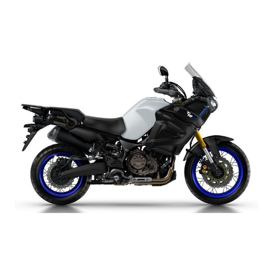
Description EAU63371 Left view 1. Fuel tank cap (page 3-30) 2. Seat lock (page 3-33) 3. Carrier (page 3-41) 4. Final gear oil filler bolt (page 6-14) 5. Final gear oil drain bolt (page 6-14) 6. Coolant reservoir (page 6-16) 7. -
Page 13: Right View
Description EAU63391 Right view 1. Rear brake fluid reservoir (page 6-25) 2. Electronically adjustable suspension system (page 3-37) 3. Fuses (page 6-32) 4. Owner’s tool kit (page 6-2) 5. Battery (page 6-30) 6. Engine oil filler cap (page 6-10) 7. Engine oil level check window (page 6-10) 8. -
Page 14: Controls And Instruments
Description EAU63401 Controls and instruments 1. Clutch lever (page 3-24) 2. Left handlebar switches (page 3-23) 3. Clutch fluid reservoir (page 6-25) 4. Multi-function meter unit (page 3-10) 5. Auxiliary DC jack (page 3-45) 6. Front brake fluid reservoir (page 6-25) 7. -
Page 15: Instrument And Control Functions
Do not grind any key or alter its cess, take the vehicle along with all shape. three keys to a Yamaha dealer to have Do not disassemble the plastic them re-registered. Do not use the key part of any key. -
Page 16: Main Switch/Steering Lock
Instrument and control functions Keep the standard keys as well EAU10474 Main switch/steering lock as keys of other immobilizer systems away from this vehi- cle’s code re-registering key. Keep other immobilizer system keys away from the main switch as they may cause signal inter- ference. - Page 17 Instrument and control functions To unlock the steering EWA10062 WARNING Never turn the key to “OFF” or “LOCK” while the vehicle is moving. Otherwise the electrical systems will be switched off, which may result in loss of control or an accident. EAU10696 LOCK The steering is locked and all electrical...
-
Page 18: Indicator Lights And Warning Lights
C.TEMP ˚C TIME TRIP 0:00 (page 6-10), have a Yamaha dealer check the vehicle. Even if the oil level is sufficient, the 1. Left turn signal indicator light “ ” warning light may flicker when rid- 2. - Page 19 If this occurs, braking. Have a Yamaha dealer have a Yamaha dealer check the on- check the brake system and electri- board diagnostic system. cal circuits as soon as possible.
- Page 20 Immobilizer system indicator do not start the engine, take the light “ ” vehicle and all 3 keys to a Yamaha When the key is turned to “OFF” and dealer to have the standard keys 30 seconds have passed, the indicator re-registered.
-
Page 21: Cruise Control System
Instrument and control functions EAU59132 Cruise control system This model is equipped with a cruise control system designed to maintain a set cruising speed. The cruise control system operates only when riding in 3rd gear at speeds between about 50 km/h (31 mi/h) and 100 km/h (62 mi/h), 4th gear at speeds between about 50 km/h (31 mi/h) and 1. - Page 22 Instrument and control functions 2. Push the “SET–” side of the cruise you return the throttle grip, the vehicle control setting switch to activate will decelerate to the previously set the cruise control system. Your cruising speed. current traveling speed will be- come the set cruising speed.
- Page 23 Instrument and control functions When not traveling with a set cruising EWA16351 WARNING speed, if the start/engine stop switch is set to the “ ” position, the engine It is dangerous to use the resume stalls, or the sidestand is lowered, then function when the previously set the “...
-
Page 24: Multi-Function Meter Unit
Instrument and control functions information display EAU80550 Multi-function meter unit setting mode 5 6 7 The select switch “ ” and the menu switch “MENU” are located on GEAR the left handlebar. These switches al- A.TEMP ˚C C.TEMP ˚C low you to control or change the set- TIME TRIP... - Page 25 Tachometer If a problem is detected in the fuel me- ter circuit, all display segments of the fuel meter will start flashing. If this oc- curs, have a Yamaha dealer check the vehicle. Eco indicator 1. Tachometer 2. High-r/min zone The tachometer shows the engine speed.
- Page 26 Instrument and control functions Transmission gear indicator Traction control system indicator GEAR A.TEMP ˚C C.TEMP ˚C TIME TRIP 0:00 1. Neutral indicator light “ ” 1. Traction control system indicator 2. Transmission gear indicator This indicator shows the current trac- This indicator shows the current trans- tion control mode: “1”, “2”...
- Page 27 Instrument and control functions Push the menu switch “MENU” to ECA17931 NOTICE switch the display between the follow- Be sure to wear gloves when ing functions. The display changes each time the switch is pushed. using the grip warmers. ...
- Page 28 Instrument and control functions average fuel consumption instantaneous fuel consumption GEAR Odometer: TRIP-F The odometer shows the total distance traveled by the vehicle. In this case, push the select switch to rotate among the information display Tripmeters: pages in the following order; TRIP-1 TRIP-F →...
- Page 29 Instrument and control functions This timer shows the elapsed time This shows the temperature of the since the key was turned to “ON”. The coolant. The coolant temperature will maximum time that can be shown is vary with changes in the ambient tem- 99:59.
- Page 30 If there is a malfunction, “– –.–” will play flashes, and then push and hold be continuously displayed. Have a the “RESET” button for 2 seconds. Yamaha dealer check the vehicle. Setting mode After resetting the average fuel con- sumption, “_ _._” will be shown until the vehicle has traveled 1 km (0.6 mi).
- Page 31 Instrument and control functions Push and hold the menu switch Adjusting the temperature levels of the “MENU” for 2 seconds to enter the set- grip warmer settings ting mode. To exit the setting mode 1. Use the select switch to highlight and return to the normal display, push “Grip Warmer”.
- Page 32 Instrument and control functions Grip Warmer MENU Grip Warmer Hi g h Maintenance Time Trip Middle Unit Display Brightness Clock 4. Use the select switch to highlight 2. Push the menu switch “MENU”, “Middle” or “Low”, and then chan- and then push the “RESET” but- ge the setting using the same pro- ton to select the item to reset.
- Page 33 Instrument and control functions MENU MENU Grip Warmer Grip Warmer Maintenance Maintenance Time Trip Time Trip Unit Unit Display Display Brightness Brightness Clock Clock 2. Push the menu switch “MENU” to 2. Push the menu switch “MENU”. display “TIME–2” and “TIME–3”. The unit setting display will be To reset a time trip, push the “RE- shown and “km or mile”...
- Page 34 Instrument and control functions 2. Push the menu switch “MENU”, use the select switch to highlight When “km” is selected, “L/100km” or the page you want to adjust, and “km/L” can be set as the fuel con- then push the menu switch sumption units.
- Page 35 Instrument and control functions 5. Repeat the previous step to make other item changes, or if you are Brightness finished adjusting the information display page items, use the select switch to highlight “ ”, and then push the menu switch “MENU” to exit.
-
Page 36: D-Mode (Drive Mode)
Instrument and control functions 6. Push the menu switch “MENU” to EAU49433 D-mode (drive mode) return to the setting mode main D-mode is an electronically controlled screen. engine performance system with two mode selections (touring mode “T” and Resetting all of the display items sports mode “S”). -
Page 37: Handlebar Switches
Instrument and control functions EAU1234M EAU12461 Handlebar switches Turn signal switch “ ” To signal a right-hand turn, push this Left switch to “ ”. To signal a left-hand turn, push this switch to “ ”. When released, the switch returns to the cen- ter position. -
Page 38: Clutch Lever
Instrument and control functions EAU12781 EAU12832 Cruise control switches Clutch lever See page 3-7 for an explanation of the cruise control system. EAU54231 Menu switch “MENU” This switch is used to perform selec- tions in the function display and setting mode display of the multi-function me- ter unit. -
Page 39: Shift Pedal
Instrument and control functions EAU12872 EAU49518 Shift pedal Brake lever The brake lever is located on the right side of the handlebar. To apply the front brake, pull the lever toward the throttle grip. This model is equipped with a unified brake system. -
Page 40: Brake Pedal
Instrument and control functions When the vehicle starts moving, EAU49483 Brake pedal the unified brake system is re-en- abled. The unified brake system does not function when the brake pedal is applied alone or before the brake lever is applied. The brake lever is equipped with a brake lever position adjusting dial. -
Page 41: Abs
However, special tools are rear brakes independently. required, so please consult your Operate the brakes with ABS as you Yamaha dealer. would conventional brakes. If the ABS ECA16831 is activated, a pulsating sensation may NOTICE... -
Page 42: Traction Control System
Instrument and control functions The traction control system indicator EAU58953 Traction control system light flashes when traction control has The traction control system helps engaged. You may notice slight chang- maintain traction when accelerating on es in engine and exhaust sounds when slippery surfaces, such as unpaved or the system has engaged. - Page 43 Instrument and control functions The traction control system mode can 4. Have a Yamaha dealer check the be changed only when the vehicle is vehicle and turn off the engine stopped. trouble warning light. Push the “TCS” button to change between modes “1”...
-
Page 44: Fuel Tank Cap
Instrument and control functions EAU13075 EAU13222 Fuel tank cap Fuel Make sure there is sufficient gasoline in the tank. EWA10882 WARNING Gasoline and gasoline vapors are extremely flammable. To avoid fires and explosions and to reduce the risk of injury when refueling, follow these instructions. - Page 45 If the same identifier when fueling. gasoline spills on your skin, wash Your Yamaha engine has been de- with soap and water. If gasoline signed to use premium unleaded gas- spills on your clothing, change your oline with a research octane number of clothes.
-
Page 46: Fuel Tank Overflow Hose
Instrument and control functions EAU79161 EAU13434 Fuel tank overflow hose Catalytic converter This model is equipped with a catalytic converter in the exhaust system. EWA10863 WARNING The exhaust system is hot after op- eration. To prevent a fire hazard or burns: ... -
Page 47: Rider Seat
Instrument and control functions The rider seat height can be ad- EAU49444 Rider seat justed to change the riding posi- tion. (See “Adjusting the rider seat To remove the rider seat height”.) 1. Insert the key into the seat lock, and then turn it counterclockwise. -
Page 48: Adjusting The Rider Seat Height
Instrument and control functions EAU49475 Adjusting the rider seat height The rider seat height can be adjusted to one of two positions to suit the rid- er’s preference. The rider seat height was adjusted to the higher position at delivery. 1. - Page 49 Instrument and control functions Make sure that the rider seat is proper- ly secured before riding. 1. Rider seat height position adjuster 3. Install the rider seat height posi- tion adjuster so that the match mark is aligned with the “H” mark as shown.
-
Page 50: Windshield
Instrument and control functions EAU58982 Windshield Make sure that the slide plate To suit the rider’s preference, the wind- holders are aligned with the match shield can be changed to one of four marks at the same height on both positions. -
Page 51: Adjusting The Front And Rear Suspension
Yamaha dealer check the sus- Preload pension system. When riding with luggage or a passen- ger, use the preload adjusting function To adjust the preload to adjust the suspension system to 1. Turn the key to “ON”, start the en- match the load. - Page 52 Instrument and control functions GEAR GEAR 1. Menu switch “MENU” While the preload is being adjusted, 2. Select switch “ ” the information display may change as 3. Use the select switch to select the follows. If the key is turned to “OFF” or the desired preload setting pictogram.
- Page 53 Instrument and control functions GEAR GEAR GEAR HARD HARD 1. Damping force setting If the preload is adjusted repeat- 2. Damping force setting level edly, the preload setting picto- gram will flash 4 times and the preload cannot be adjusted. Wait If the preload setting was not complet- approximately 6 minutes for the ed correctly:...
- Page 54 Instrument and control functions GEAR The damping force setting can be set to 7 levels (+3, +2, +1, 0, –1, –2 and –3). “+3” is the hardest level and “–3” is the softest level. 6. Push the menu switch “MENU”. If the vehicle moves while you are ad- justing the damping force, the informa- 1.
-
Page 55: Carriers
Take the shock ity of the standard carrier. absorber assembly to a Yamaha To use the additional carrier, consult a dealer for any service. Yamaha dealer. Standard carrier 1. -
Page 56: Luggage Strap Holders
Instrument and control functions Do not exceed the standard car- EAU49491 Luggage strap holders rier capacity of 5.0 kg (11 lb). Do not exceed the additional carrier capacity of 5.0 kg (11 lb). ECA16822 NOTICE Do not lift the vehicle by either carri- 1. -
Page 57: Sidestand
Therefore, check this system regularly and have a Yamaha dealer repair it if it does not function properly. 3-43... - Page 58 Does the engine start? The neutral switch may not be working correctly. The motorcycle should not be ridden until checked by a Yamaha dealer. With the engine still running: 6. Move the sidestand up. 7. Keep the clutch lever pulled.
-
Page 59: Auxiliary Dc Jack
Instrument and control functions EAU49453 Auxiliary DC jack EWA14361 WARNING To prevent electrical shock or short- circuiting, make sure that the cap is installed when the auxiliary DC jack is not being used. ECA15432 NOTICE 1. Auxiliary DC jack The accessory connected to the 5. -
Page 60: For Your Safety - Pre-Operation Checks
Do not operate the vehicle if you find any problem. If a problem cannot be corrected by the procedures provided in this manual, have the vehicle inspected by a Yamaha dealer. Before using this vehicle, check the following points:... - Page 61 • Tighten if necessary. Instruments, lights, • Check operation. — • Correct if necessary. signals and switches • Check operation of ignition circuit cut-off system. Sidestand switch • If system is not working correctly, have Yamaha dealer 3-43 check vehicle.
-
Page 62: Operation And Important Riding Points
This model is equipped with: there is a control or function you do not a lean angle sensor to stop the en- understand, ask your Yamaha dealer. gine in case of turnover. In this EWA10272 case, turn the key “OFF” and then WARNING to “ON”... -
Page 63: Starting The Engine
The neutral indi- the clutch lever pulled and the cator light should come on. If not, sidestand up. ask a Yamaha dealer to check the See page 3-43 for more informa- electrical circuit. tion. 3. Start the engine by pushing 1. -
Page 64: Shifting
Operation and important riding points EAU16673 and drive train, which are not Shifting designed withstand shock of forced shifting. 1. Shift pedal 2. Neutral position Shifting gears lets you control the amount of engine power available for starting off, accelerating, climbing hills, etc. -
Page 65: Tips For Reducing Fuel Consumption
Operation and important riding points EAU16811 EAU16842 Tips for reducing fuel con- Engine break-in sumption There is never a more important period in the life of your engine than the period Fuel consumption depends largely on between 0 and 1600 km (1000 mi). For your riding style. -
Page 66: Parking
EAU17214 Parking cur during the engine break-in When parking, stop the engine, and period, immediately have a then remove the key from the main Yamaha dealer check the vehi- switch. cle. EWA10312 WARNING Since the engine and exhaust system can become very hot,... -
Page 67: Periodic Maintenance And Adjustment
If you are not familiar with vehicle ser- vice, have a Yamaha dealer perform service. EWA15123 WARNING Turn off the engine when performing... -
Page 68: Owner's Tool Kit
If you do not have the tools or experi- ence required for a particular job, have a Yamaha dealer perform it for you. -
Page 69: Periodic Maintenance Chart For The Emission Control System
From 50000 km (30000 mi), repeat the maintenance intervals starting from 10000 km (6000 mi). Items marked with an asterisk should be performed by a Yamaha dealer as they require special tools, data and technical skills. EAU71071... -
Page 70: General Maintenance And Lubrication Chart
• Perform dynamic inspection Diagnostic system √ √ √ √ √ √ using Yamaha diagnostic tool. check • Check the error codes. 2 * Air filter element • Replace. Every 40000 km (24000 mi) • Check operation, fluid level and √... - Page 71 Periodic maintenance and adjustment ODOMETER CHECK OR READINGS MAINTENANCE JOB ITEM X 1000 km X 1000 mi • Make sure that all nuts, bolts √ √ √ √ √ 13 * Chassis fasteners and screws are properly tight- ened. Brake lever pivot √...
- Page 72 Periodic maintenance and adjustment ODOMETER CHECK OR READINGS MAINTENANCE JOB ITEM X 1000 km X 1000 mi • Check oil level and vehicle for √ √ √ √ √ oil leakage. 26 * Final gear oil √ √ √ • Change. Front and rear √...
-
Page 73: Removing And Installing Cowlings
Periodic maintenance and adjustment EAU18782 Removing and installing cowl- ings The cowlings shown need to be re- moved to perform some of the mainte- nance jobs described in this chapter. Refer to this section each time a cowl- ing needs to be removed and installed. 1. - Page 74 Periodic maintenance and adjustment 1. Cowling B 1. Cowling C 2. Bolt 2. Nut 3. Bolt 1. Quick fastener 1. Cowling C 2. Nut To install the cowling 3. Bolt 1. Place the cowling in the original position, and then install the bolts To install the cowling and the quick fasteners.
-
Page 75: Checking The Spark Plugs
The spark plugs are important engine components, which should checked periodically, preferably by a Yamaha dealer. Since heat and depos- its will cause any spark plug to slowly erode, they should be removed and checked in accordance with the peri- odic maintenance and lubrication 1. -
Page 76: Canister
Periodic maintenance and adjustment EAU79401 EAU49506 Canister Engine oil and oil filter car- tridge The engine oil level should be checked before each ride. In addition, the oil must be changed and the oil filter car- tridge replaced at the intervals speci- fied in the periodic maintenance and lubrication chart. - Page 77 Periodic maintenance and adjustment 4. If the engine oil is below the mini- mum level mark, add sufficient oil of the recommended type to raise it to the correct level. Check the O-ring for damage, and re- place it if necessary. 1.
- Page 78 Tightening torque: Oil filter cartridge: 17 N·m (1.7 kgf·m, 13 lb·ft) An oil filter wrench is available at a Yamaha dealer. 11. Install the cowling. 12. Install the engine oil drain bolts 9. Apply a thin coat of clean engine...
- Page 79 Do off and have a Yamaha dealer check not use oils with a diesel speci- the vehicle. fication of “CD” or oils of a high- 17.
-
Page 80: Final Gear Oil
Final gear oil The final gear case must be checked for oil leakage before each ride. If any leakage is found, have a Yamaha deal- er check and repair the vehicle. In ad- dition, the final gear oil level must be... - Page 81 5. Refill with the recommended final gear oil to the brim of the filler hole. Recommended final gear oil: Yamaha genuine shaft drive gear oil SAE 80W-90 API GL-5 or SAE 80 API GL-4 Hypoid gear oil Oil quantity: 0.20 L (0.21 US qt, 0.18 Imp.qt) 6.
-
Page 82: Coolant
If water has been added to the coolant, have a Yamaha dealer check the anti- freeze content of the coolant as soon as possible, otherwise the effectiveness of the coolant will 1. -
Page 83: Air Filter Element
Have a maintenance and lubrication chart. Yamaha dealer change the coolant. Have a Yamaha dealer replace the air WARNING! Never attempt to remove filter element. the radiator cap when the engine is hot. -
Page 84: Checking The Engine Idling Speed
Yamaha dealer. Engine idling speed: 1050–1150 r/min 1. Throttle grip free play Throttle grip free play: 3.0–5.0 mm (0.12–0.20 in) Periodically check the throttle grip free play and, if necessary, have a Yamaha dealer adjust it. 6-18... -
Page 85: Valve Clearance
Therefore, it must be adjusted by a Yamaha dealer is essential to maintain the tires in good at the intervals specified in the periodic condition at all times and replace them maintenance and lubrication chart. - Page 86 If the center tread depth reaches the specified limit, if the tire has a nail or glass fragments in it, or if the side- wall is cracked, have a Yamaha dealer replace the tire immediately. 1. Tire air valve 2.
- Page 87 After extensive tests, only the tires list- ed below have been approved for this model by Yamaha. Front tire: Size: 110/80R19M/C 59V Manufacturer/model: BRIDGESTONE/BW501...
-
Page 88: Spoke Wheels
If any damage is poor acceleration, there may be air in found, have a Yamaha dealer re- the clutch system. If there is air in the place the wheel. Do not attempt... -
Page 89: Checking The Brake Lever Free Play
Since the brake light switches are components of the cruise control system, they must be adjusted by a Yamaha dealer, who has the nec- essary professional knowledge and ex- perience. 1. No brake lever free play There should be no free play at the brake lever end. -
Page 90: Checking The Front And Rear Brake Pads
If a brake pad is damaged or if the lining thickness is less than 0.8 mm (0.03 in), have a Yamaha dealer replace the brake pads as a set. 1. Brake pad wear indicator Each front brake pad is provided with... -
Page 91: Checking The Brake Fluid Level
Specified brake fluid: brake system for leakage. If the brake DOT 4 fluid level goes down suddenly, have a Yamaha dealer check the cause before EWA16011 WARNING further riding. Improper maintenance can result in loss of braking ability. -
Page 92: Changing The Brake And Clutch Fluids
In addition, have ed by a Yamaha dealer at the intervals the oil seals of the brake and clutch specified in the periodic maintenance master cylinders and calipers as well chart. -
Page 93: Checking And Lubricating The Brake And Shift Pedals
Periodic maintenance and adjustment EAU44276 EAU43602 Checking and lubricating the Checking and lubricating the brake and shift pedals brake and clutch levers The operation of the brake and shift The operation of the brake and clutch pedals should be checked before each levers should be checked before each ride, and the pedal pivots should be lu- ride, and the lever pivots should be lu-... -
Page 94: Checking And Lubricating The Centerstand And Sidestand
The operation of the centerstand and The swingarm pivots must be lubricat- sidestand should be checked before ed by a Yamaha dealer at the intervals each ride, and the pivots and metal-to- specified in the periodic maintenance metal contact surfaces should be lubri- and lubrication chart. -
Page 95: Checking The Front Fork
If any free there is no danger of it falling play can be felt, have a Yamaha over. dealer check or repair the steer- [EWA10752] 2. -
Page 96: Checking The Wheel Bearings
A. (See page 6-7.) hub or if the wheel does not turn This model is equipped with a VRLA smoothly, have a Yamaha dealer (Valve Regulated Lead Acid) battery. check the wheel bearings. There is no need to check the electro- lyte or to add distilled water. - Page 97 ECA16531 NOTICE To charge the battery Always keep the battery charged. Have a Yamaha dealer charge the bat- Storing a discharged battery can tery as soon as possible if it seems to cause permanent battery damage. have discharged. Keep in mind that the...
-
Page 98: Replacing The Fuses
Periodic maintenance and adjustment EAU58963 Replacing the fuses The fuse boxes and the ABS motor fuse are located behind cowling A, and the main fuse, the cruise control fuse and the brake light fuse are located be- hind cowling B. (See page 6-7.) 1. -
Page 99: Replacing A Headlight Bulb
4. If the fuse immediately blows again, have a Yamaha dealer check the electrical system. 1. Do not touch the glass part of the bulb. 1. Remove the headlight bulb cover by turning it counterclockwise. - Page 100 Periodic maintenance and adjustment 6. Install the headlight bulb cover by turning it clockwise. 7. Have a Yamaha dealer adjust the headlight beam if necessary. 1. Headlight bulb cover 2. Disconnect the headlight coupler. 1. Headlight coupler 3. Unhook the headlight bulb holder, and then remove the burnt-out bulb.
-
Page 101: Replacing An Auxiliary Light Bulb
Periodic maintenance and adjustment EAU58971 Replacing an auxiliary light bulb This model is equipped with two auxil- iary lights. If an auxiliary light bulb burns out, replace it as follows. 1. Remove the windshield by remov- ing the screws. 1. Panel 2. - Page 102 Periodic maintenance and adjustment 1. Headlight unit 1. Auxiliary light bulb 2. Headlight unit bolt 8. Insert a new bulb into the socket. 9. Install the socket (together with the bulb) by pushing it in and turn- ing it clockwise. 10.
-
Page 103: Turn Signal Light And Brake/Tail Light
This model is equipped with LED-type turn signal lights and an LED-type Tightening torque: Windshield screw: brake/tail light. 0.5 N·m (0.05 kgf·m, 0.37 lb·ft) If a turn signal light or the brake/tail light does not come on, have a Yamaha dealer check it. 6-37... -
Page 104: Replacing A License Plate Light Bulb
Periodic maintenance and adjustment EAU49722 Replacing a license plate light bulb 1. Remove the license plate light unit bolts. 1. License plate light bulb 4. Insert a new bulb into the socket. 5. Install the socket (together with the bulb) by pushing it in, and then turning it clockwise until it stops. -
Page 105: Troubleshooting
The following troubleshooting charts represent quick and easy procedures for checking these vital systems your- self. However, should your motorcycle require any repair, take it to a Yamaha dealer, whose skilled technicians have the necessary tools, experience, and know-how to service the motorcycle properly. -
Page 106: Troubleshooting Charts
Check the vehicle. compression. 4. Compression The engine does not start. There is compression. Have a Yamaha dealer check the vehicle. Operate the electric starter. There is no Have a Yamaha dealer check the vehicle. compression. 6-40... - Page 107 Start the engine. If the engine overheats again, The coolant level is have a Yamaha dealer check and repair the cooling system. If coolant is not available, tap water can be temporarily used instead, provided that it is changed to the recommended coolant as soon as possible.
-
Page 108: Motorcycle Care And Storage
Rust and corrosion can develop matte colored finished parts. Be even if high-quality components are sure to consult a Yamaha dealer for used. A rusty exhaust pipe may go un- advice on what products to use be- noticed on a car, however, it detracts fore cleaning the vehicle. - Page 109 Motorcycle care and storage structed. Also, thoroughly rinse compounds for plastic may the area off with water, immedi- leave scratches on the wind- ately dry it, and then apply a cor- shield. Test the product on a rosion protection spray. small hidden part of the wind- ...
- Page 110 3. To prevent corrosion, it is recom- Consult a Yamaha dealer for ad- mended to apply a corrosion pro- vice on what products to use. tection spray metal, ...
-
Page 111: Storage
Motorcycle care and storage der head so that the electrodes EAU49592 Storage are grounded. (This will limit sparking during the next step.) Short-term d. Turn the engine over several Always store your motorcycle in a cool, times with the starter. (This will dry place and, if necessary, protect it coat the cylinder walls with oil.) against dust with a porous cover. - Page 112 Motorcycle care and storage Make any necessary repairs before storing the motorcycle.
-
Page 113: Specifications
Final gear oil: 2250 mm (88.6 in) Overall width: Type: 980 mm (38.6 in) Yamaha genuine shaft drive gear oil SAE Overall height: 80W-90 API GL-5 or SAE 80 API GL-4 1410/1470 mm (55.5/57.9 in) Hypoid gear oil Seat height: Quantity: 845/870 mm (33.3/34.3 in) - Page 114 Specifications 2nd: Front wheel: 2.063 (33/16) Wheel type: 3rd: Spoke wheel 1.571 (33/21) Rim size: 4th: 19M/C x MT2.50 1.250 (30/24) Rear wheel: 5th: Wheel type: 1.042 (25/24) Spoke wheel 6th: Rim size: 0.929 (26/28) 17M/C x MT4.00 Chassis: Unified brake system: Frame type: Operation: Backbone...
- Page 115 Specifications Battery: Terminal fuse 1: 3.0 A Model: Headlight fuse: YTZ12S 20.0 A Voltage, capacity: Brake light fuse: 12 V, 11.0 Ah (10 HR) 1.0 A Headlight: Signaling system fuse: Bulb type: 7.5 A Halogen bulb Ignition fuse: Bulb wattage: 20.0 A Headlight: Parking lighting fuse:...
-
Page 116: Consumer Information
Yamaha dealer. area. VEHICLE IDENTIFICATION NUMBER: EAU26442 Engine serial number... -
Page 117: Diagnostic Connector
Consumer information the space provided. This information EAU69910 Diagnostic connector will be needed when ordering spare parts from a Yamaha dealer. 1. Diagnostic connector The diagnostic connector is located as shown. -
Page 118: Vehicle Data Recording
Vehicle status and engine perfor- mance data Fuel-injection and emission-relat- ed data Yamaha will not disclose this data to a third party except: With the consent of the vehicle owner Where obligated by law ... -
Page 119: Index
Index Fuel tank cap ........3-30 Fuel tank overflow hose......3-32 ABS ............3-27 Fuses, replacing........6-32 ABS warning light........3-5 Air filter element ........6-17 Auxiliary DC jack ........3-45 Handlebar switches ......3-23 Auxiliary light bulb, replacing ....6-35 Hazard switch ........ - Page 120 Index Suspension, adjusting the front and rear .............3-37 Swingarm pivots, lubricating ....6-28 Throttle grip and cable, checking and lubricating...........6-26 Throttle grip free play, checking ...6-18 Tires ............6-19 Tool kit ............6-2 Traction control system ......3-28 Traction control system indicator light ...3-5 Troubleshooting........6-39 Troubleshooting charts......6-40 Turn signal indicator lights......3-4...
- Page 122 Original instructions PRINTED ON RECYCLED PAPER PRINTED IN JAPAN 2017.02-0.3×1 CR...
Need help?
Do you have a question about the Super Tenere ABS XT1200ZE and is the answer not in the manual?
Questions and answers