
Related Manuals for SPAN F500S


Summary of Contents for SPAN F500S
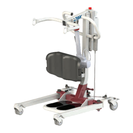
- Page 1 OWNER’S MANUAL Model: F500S SIT-TO-STAND PATIENT LIFT Ensure the product has been assembled according to the instructions in this manual. All operators should read and understand the instructions for safe and proper operation of the patient lift. P11584...
-
Page 2: Date Of Manufacture
Refuse delivery if the packaging appears to be badly damaged. If the merchandise is damaged or any component is missing, contact the shipping company immediately and fi le a claim. For further assistance, contact your local dealer or Span-America. DEFINITIONS & SYMBOLS n this manual the user refers to the patient or resident and may be used interchangeably at different times. -
Page 3: Safety Instructions
• Never leave the user/patient unattended during lifting. The F500S can assist a person to be lifted and transferred safely, with minimum physical effort provided by the caregiver. Before attempting to lift anyone, please practice operating the lift. - Page 4 Unauthorized use of any modifi ed equipment may result in serious injury or death. • DO NOT replace any components of the lift without consulting with Span, and follow proper instructions when replacing any components.
-
Page 5: Features And Overview
FEATURES & OVERVIEW Prior to assembly, unpack all parts from the shipping carton and check for any missing parts. Contact you dealer immediately if a part is missing. Easy Tools Screw Driver 2920 PACIFIC DRIVE UNLESS OTHERWISE SPECIFIED: NORCROSS, GA 30071 ALL DIMENSIONS IN MM DRAWN BY: DATE:... - Page 6 F500S mm (in) A 1500.5 (59.1) 559.7 (22.0) 940.7 (37.0) 19.8 (0.8) 386.8 (15.2) 816.1 (32.1) 749.8 (29.5) 547 (21.5) 291.9 (11.5) 646.3 (25.4) 200.8 (7.9) 201.2 (7.9) 123.4 (4.9) 33.4 (1.3)
-
Page 7: Specifications And Options
F500S Lift Weight Unloaded (lb) 107.1 Lift Weight Unloaded (kg) 48.7 * Span-America is committed to continuous improvements of our products therefore the specs, dimensions, and features listed above are for guidance only and subject to change without prior notice. - Page 8 F500S TC12 Control Box TA24 Actuator...
- Page 9 Installation Step 1: Base and Mast Step 2: Boom...
- Page 10 Step 3: Footplate Step 4: Actuator...
- Page 11 Step 5: Knee Pad...
- Page 12 Step 6: Power Control Unit M5 SCREWS M4 SCREWS 2920 PACIFIC DRIVE UNLESS OTHERWISE SPECIFIED: NORCROSS, GA 30071 ALL DIMENSIONS IN MM DRAWN BY: DATE: 9/27/2017 6-30 PART NUMBER: 30-120 M4x0.7x10mm Machine Screw PROPRIETARY AND CONFIDENTIAL 120-400 THE INFORMATION CONTAINED IN THIS MATERIAL: DESCRIPTION: DRAWING IS THE SOLE PROPERTY OF...
- Page 13 Power Control Unit Overview Emergency Stop Button Up / Down Button Battery Pack Release Handle LCD Display Panel Battery Pack Charger DC In Not Used Additional Battery Pack (Optional) Charging Cradle Actuator (Optional) Hand Control 1. Connect Actuator as shown above. 2.
-
Page 14: Operating Instructions
Operating Instructions Double check all assemblies for tightness and read operating instructions carefully prior to use. For optimum performance the lift should be transported and stored in following condition range: • -25°C to +5°C (-13°F to 41°F), and • +5°C to +35°C (41°F to 95°F) at a non-condensing relative humidity 0% to 90% •... - Page 15 Release Pressed in LCD Display Panel Signs When the emergency stop button is released, the LCD Display Panel will show one of the four signs below. • The sign will display for 5 seconds. • Then the lift will go into standby mode and the sign disappears. •...
- Page 16 Operating Lift: Using Hand Control LED Indicator Lifting * Green = In Use * Blank = Standby Lowering Operating Lift: Using LCD Display Panel...
- Page 17 Warning! - Battery Low and Charging is Needed If the battery needs to be charged, the LCD Display Panel will show a blinking low battery sign shown on the left either when the emergency stop button is released or when a button on the LCD Display Panel is pressed.
- Page 18 Available slings compatible with Stand Assist Lift Stand Assist Sling Sling Model Sling Size D202MEDLP S / M D202XLRGLP L / XL Stand Assist Buttock Strap Sling Model Strap Size SL-SA669 Standard SL-SA669B Bariatric Sling Model Sling Description Knee Belt WP-SA400E-KB If the patient is pregnant or has skin conditions, con- sult with doctor before use.
- Page 19 FITTING STAND ASSIST SLING • Position the patient in a sitting position. • Slide the sling down patient’s back to lumbar position. • Draw the shoulder staps to the front of the patient close to the chest. • Draw the waist belt around patient’s waist and press together to fasten. Attach the shoulder straps to the hooks.
- Page 20 This sling is designed to support the middle and lower part of the body. • Attach the sling strap “A” to the hook “a” on the boom of the F500S lift as in Diagram 1. Bringing the other side around the back of the patient’s but- tocks (to fi t like a park swing) and attach to hook “b”.
- Page 21 LIFT AND TRANSFER FROM BED • Fit sling as described in “Fitting Stand Assist Sling”. • Push lift towards patient. Open the base of the lift. • Position patient’s feet on the footplate and knees against the knee pad. • Attached the sling straps to the hooks. •...
-
Page 22: Maintenance And Inspection
• With proper use and care, the expected lifetime of the lift is 10 years or 20,000 cycles. • The expected lifetime of the electrical components are 3 years. • Contact Span-America for recycling information First Received Monthly Every 3 Months Boom &... -
Page 23: Cleaning And Disinfecting
• REPLACE a sling when it show signs of deterioration. Deterioration of sling • Contact Span for “Guideline for Identifying Deteriorated Slings” if needed. Disinfecting of the lift and sling • Inspect slings prior to each use for contamination from previous use. -
Page 24: Troubleshooting Guide
Troubleshooting Guide The following list of encountered problems and solutions will assist you in determining what may be causing your patient lift not to function as designed. If you have a problem occurring which is not listed below please contact your dealer or technical support for help. - Page 25 Emergency Lowering Mechanism Contact your dealer immediately if standard troubleshooting techniques do not correct the failure. Do not attempt to lift until all failure and safety issues have been resolved. In case of lift failure, please follow the procedures below to safely lower the user. The Emergency Lowering Device is located at the top of the actuator shaft.
- Page 26 RETURN GOODS POLICY Patient lifts may not be returned unless the wrong lift is shipped in error by Span or the lift is heavily damaged or defective out of the box. For all other items, purchaser may request a RA for purchased goods within thirty (30) days of purchase invoice date.
Need help?
Do you have a question about the F500S and is the answer not in the manual?
Questions and answers