Sign In
Upload
Manuals
Brands
Digital Equipment Manuals
Desktop
AlphaStation 600 Series
Digital Equipment AlphaStation 600 Series Manuals
Manuals and User Guides for Digital Equipment AlphaStation 600 Series. We have
2
Digital Equipment AlphaStation 600 Series manuals available for free PDF download: User Information, Information Sheet
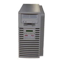
Digital Equipment AlphaStation 600 Series User Information (149 pages)
Brand:
Digital Equipment
| Category:
Desktop
| Size: 1 MB
Table of Contents
Table of Contents
5
1 Getting Started
19
Introduction
19
Before Starting Your System
20
Figure 1-1. Alphastation 600 Series System
20
Posture and Work Habits
21
Figure 1-2. Recommendations for Posture and Work Habits
22
Table 1-1. Recommendations for Posture and Work Habits
22
Identifying the Correct AC Power Cord
24
Installing Your System
25
Figure 1-3. System Airflow (Side View, Cover Removed)
26
Connecting System Components
27
Figure 1-4. Connecting Cables and the Power Cord
28
Network Connection
29
Starting Your System
29
Preloaded Operating System Software
30
Figure 1-5. Starting Your System
30
Dec Osf/1
31
Openvms
31
Switching Console Firmware
31
If no Operating System Is Installed
31
Turning off Your System
32
Table 1-2. System Shutdown Commands
32
Computer Security
33
Security Lock
33
Passwords
33
2 System Overview
35
Introduction
35
System Unit
35
PCI Architecture
36
Alphastation 600 Series I/O Subsystem
36
The Keyboard
36
Figure 2-1. Typical Keyboard Layout
37
Table 2-1. Key Groups and Functions
37
System Front Panel
38
Figure 2-2. Front Controls, Indicators, and Drive Bay Locations
38
Table 2-2. Front Controls, Indicators, and Drive Bay Locations
38
System Rear Panel
40
Table 2-3. Rear Connectors
41
3 Installing System Options
43
Introduction
43
System Unit Components
44
Figure 3-1. System Unit Components
44
Table 3-1. System Unit Components
44
Left Side Panel
45
Removing the Left Side Panel
45
Figure 3-2. Unlocking and Removing the Left Side Panel
46
Replacing the Left Side Panel
47
Figure 3-3. Replacing the Left Side Panel
47
System Board
48
Figure 3-4. System Board Components
49
Table 3-2. System Board Components
49
System Memory
50
Cache Memory
50
Random-Access Memory
50
Figure 3-5. Populating a Memory Tower
51
Adding a SIMM to a Memory Tower
52
Figure 3-6. Removing a Memory Tower
53
Figure 3-7. Installing a SIMM
54
Replacing the Cache Memory Modules
55
External Drive Bay Devices
56
SCSI Addresses
56
SCSI Termination
56
Table 3-3. SCSI Address Recommendations
56
Installing External Drive Bay Devices
57
Figure 3-8. Removing a Plastic Filler Panel
57
Figure 3-9. Attaching the Securing Bracket and Installing the Device
59
Figure 3-10. SCSI and Removable Device Connector Cable Configuration
60
Figure 3-11. Power Cable Configuration
61
Internal Drive Bay Devices
63
Removing the Drive Assembly from the System Unit
63
Figure 3-12. Removing the Drive Assembly
64
Removing a Device from the Drive Assembly
65
Figure 3-13. Removing a Device from the Drive Assembly
65
Replacing the Drive Assembly in the System Unit
66
ISA, EISA, and PCI Expansion Options
67
ISA Bus
67
Figure 3-14. ISA, EISA, and PCI Expansion Module Contacts
67
EISA Bus
68
PCI Bus
68
Figure 3-15. EISA/ISA Slot Numbering
68
Installing Expansion Modules
69
Figure 3-16. Installing an Expansion Module
70
The Operator Control Panel
72
Rotating the OCP
72
Figure 3-17. Removing the Front Bezel
72
Figure 3-18. Rotating the OCP
73
4 Troubleshooting
75
Introduction
75
Initial Troubleshooting
75
General Troubleshooting
76
Table 4-1. System Troubleshooting
76
Table 4-2. Disk Drive Troubleshooting
80
Table 4-3. Monitor Troubleshooting
81
Status and Error Codes
82
Table 4-4. Status and Error Codes
82
Equipment Log
83
A Console Commands
85
Introduction
85
ARC Console
85
Commands You Need to Know
86
Display Hardware Configuration
86
Set Default Environment Variables
86
Set Default Configuration
86
Manage Boot Selection Menu
86
Machine Specific Setup
87
Boot (Boot Selection Identifier
87
Boot an Alternate Operating System
87
Other Commands of Interest
87
Setup Autoboot
87
Install New Firmware
87
Install Windows NT from CD-ROM
88
Switch to Openvms or OSF Console
88
SRM Console
89
SRM Console Conventions
89
Table A-1. SRM Console Conventions
89
SRM Console Shortcut Keys
90
Table A-2. SRM Console Shortcut Keys
90
Boot Command
91
Boot Command Examples
92
Table A-3. Boot Command Examples
92
ECU Command
93
Set Command
93
Set Command Examples
94
Show Command
94
Table A-4. Set Command Examples
94
Show Command Examples
95
Table A-5. Show Command Examples
95
Environment Variables
96
Table A-6. Environment Variables
96
Examine Command
97
Examine Command Examples
98
Table A-7. Examine Command Examples
98
Deposit Command
99
Deposit Command Examples
100
Table A-8. Deposit Command Examples
100
Using the EISA Configuration Utility
101
Before You Run the ECU
101
Configuring EISA Options
102
Configuring ISA Options
104
B System Care
107
Introduction
107
Cleaning Your System Unit
107
Cleaning Your Monitor
107
Cleaning Your Mouse
108
Cleaning Your Keyboard
109
Moving Your System
109
Figure B-1. Cleaning the Mouse
109
Installing Your System at a New Location
110
Packing Your System
110
C Technical Specifications
111
Introduction
111
System Specifications
111
Table C-1. System Specifications
112
Table C-2. System Dimensions
112
Table C-3. System Environmental Specifications
112
External System Connectors
113
Table C-4. Acoustics-Declared Values According to ISO 9296 and ISO 7779
113
Parallel Port Connector
114
Table C-5. Parallel Port Pinouts
114
Serial Port Connectors
115
Keyboard and Mouse Connectors
115
Table C-6. 9-Pin Port Pinouts
115
Table C-7. Keyboard and Mouse Connector Pinouts
115
SCSI Connectors
116
Table C-8. Wide SCSI Pinouts
116
Table C-9. Narrow SCSI Pinouts
117
Expansion Slots
118
Power Supply and Input Power Requirements
119
Table C-10. Output Power Requirements
119
Table C-11. Input Power Requirements
119
System Board Jumper Locations
120
Figure C-1. System Board Jumper Locations
121
Table C-12. System Board Jumpers
122
I/O Subsystem Module
123
SCSI Controller
123
Table C-13. I/O Subsystem Module Jumpers
123
Ethernet Interface
124
Thick Wire Jumpering
124
Thinwire or Twisted-Pair Jumpering
124
Software Switches
124
Figure C-2. I/O Subsystem Module Jumper/Connector Locations
125
D Device Mapping
127
Introduction
127
I/O Address Map
127
Table D-1. I/O Address Map
127
Interrupt Map
128
Table D-2. Main Interrupt Logic IRQ Pin Assignments
128
Table D-3. EISA Interrupt Assignments
129
E Updating System Firmware
131
Introduction
131
System Firmware
131
Update Utility
131
Flash Enable Jumper
131
Using the Flash Update Utility
131
F Starting an Operating System Installation
137
Introduction
137
Starting a DEC OSF/1 Installation
138
Table F-4. Starting a DEC OSF/1 Installation
138
Starting an Openvms Installation
139
Table F-5. Starting an Openvms Installation
139
Table G-1. Hardware Components
142
Table G-2. SCSI Addresses
142
Table G-3. Hardware Configuration
143
Advertisement
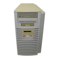
Digital Equipment AlphaStation 600 Series Information Sheet (4 pages)
333 MHz Upgrade
Brand:
Digital Equipment
| Category:
Desktop
| Size: 0 MB
Table of Contents
Introduction
1
Tools Required
1
Upgrade Procedure
1
Figure 1: Removing the OCP Cables
2
Figure 2: Rerouting the OCP Cables
3
Figure 3: Installing the EMI Gaskets
4
Advertisement
Related Products
Digital Equipment AlphaStation 500 Series
Digital Equipment Digital AlphaStation 400 Series
Digital Equipment DECpc AXP 150
Digital Equipment Alpha
Digital Equipment Adaptec AHA-1742A
Digital Equipment AlphaStation
Digital Equipment AlphaPC64
Digital Equipment AlphaServer 2000
Digital Equipment AlphaServer 1000
Digital Equipment AlphaServer 2100
Digital Equipment Categories
Desktop
Server
Computer Hardware
Printer
Storage
More Digital Equipment Manuals
Login
Sign In
OR
Sign in with Facebook
Sign in with Google
Upload manual
Upload from disk
Upload from URL