andrews CWH 30/201 Operating Instructions Manual

High efficiency condensing stainless steel storage water heater

Advertisement

Quick Links

CONTROLS OPERATING INSTRUCTION MANUAL
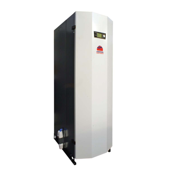
MAXXfl o EVO
High effi ciency condensing stainless steel storage water heater
CWH 30/201, CWH 30/301, CWH 60/201, CWH 60/301
CWH 90/302, CWH120/302
Please read and understand these instructions before commencing installation and leave this manual with the customer for future reference.
Andrews. Built to perform.
M8673

Advertisement

Table of Contents
loading

Summary of Contents for andrews CWH 30/201

  • Page 1 MAXXfl o EVO High effi ciency condensing stainless steel storage water heater CWH 30/201, CWH 30/301, CWH 60/201, CWH 60/301 CWH 90/302, CWH120/302 Please read and understand these instructions before commencing installation and leave this manual with the customer for future reference.
  • Page 2 Blank Page MAXXfl o EVO...
  • Page 3: Table Of Contents

    TABLE OF CONTENTS Subject Page Warnings and important notices Introduction to the controls The heater controls The Graphical User Interface (GUI) Navigate and set using the control knob Display symbol meanings End user operation The home page Setting the time and date Setting DHW heating time program Setting DHW temperature Setting DHW operating mode...
  • Page 4 Any other use of this heater will be considered improper. Andrews Water Heaters declines any responsibility for any damage or injuries caused by an improper use. In order to use the heater according to its designed scope, it is essential to carefully follow the instructions given in this guide.
  • Page 5 MAINTENANCE & CONDENSATION OUTLET To ensure continued effi cient operation of the heater it is recommended that the condensate outlet is checked and serviced at regular intervals. The frequency of servicing will depend upon the particular installation and usage but in every case a maximum of twelve months should be allowed between service inspections.
  • Page 6 NORMAL CAPACITY The capacity in litres of the in-built DHW tank is given in the table below:- Tank size 200 litres 300 litres Models CWH 30/201 CWH 30/301 CWH 60/201 CWH 60/301 CWH 90/302 CWH 120/302 HEATER INSTALLATION AND MAINTENANCE This heater has been designed for use with G20 and G31 gases and is manufactured to give an effi...
  • Page 7: The Heater Controls

    1.0 INTRODUCTION 1.1 HEATER CONTROLS Cascade fl ow temp 60.3 DHW temp 1 58.2 Operation switch Reset switch Control knob (push to enter) Graphical User Interface 1.2 THE GRAPHICAL USER INTERFACE The control knob is used to operate the GUI. The display is organised into a navigation bar, status bar, and work area.
  • Page 8: Navigate And Set Using The Control Knob

    1.3 NAVIGATE AND SET USING THE CONTROL KNOB Operating objects may have three display states: Not selected: The operating object is displayed normally, black on white background. Preselected: The operating object is framed. Selected: The operating object is inverted with white on black background. To go to the navigation bar: Turn control knob.
  • Page 9: Display Symbol Meanings

    1.4 DISPLAY SYMBOL MEANINGS The following symbols are located on the navigation bar (left, vertical): Accessible for end-user and experts: Start page: Heater status. Access to system operation mode. DHW page. Access to temperature and time clock settings Info pages: •...
  • Page 10: End User Operation

    2.0 END USER OPERATION 2.1 THE HOME PAGE Evaluation of information displayed: Line only displayed for Cascade fl ow temp 60.1 90 or 120 kW models DHW temp 1 58.9 Heater GUI Display The start page for the heater GUI unit displays the most important information on the water heater and system operation mode.
  • Page 11: Setting Dhw Heating Time Program

    2.3 SETTING DHW HEATING TIME PROGRAM In order to set the DHW heating time program the Domestic Hot Water operation mode of the heater must be set to “ON”. This is achieved by turning the operation switch on the front facia of the heater from standby (0) to on (I) OPERATION SWITCH Select the Domestic Hot Water (DHW) tab by rotating the control knob and pressing the control knob.
  • Page 12 Select the day fi eld to change the times of that day Domestic hot water Monday Tuesday Wednesday Thursday Friday Saturday Sunday Back Turn and push the control knob to set the start and end times of the program. Scroll to the beginning (00 hours) to insert another time band (up to a total of 3 time bands per day can be set).
  • Page 13: Setting Dhw Temperature

    Using the control knob select the day to be copied to and press the control knob. Repeat this operation as required. Copy Monday to Monday Tuesday Wednesday Thursday Friday Saturday Sunday Done Once times have been copied select “Done “ to return to Domestic hot water page. Copy Monday to Monday Tuesday...
  • Page 14: Setting Dhw Operating Mode

    2.5 SETTING DHW OPERATING MODE Changing the operating mode is achieved using the operation switch on the front of the facia (see below). OPERATION SWITCH When operation switch is set to position O (STANDBY), DHW operating mode should be OFF (see example below) Domestic hot water Operating mode Off...
  • Page 15: Temporary Dhw Operation Function

    2.6 TEMPORARY DHW OPERATION FUNCTION Outside of the programmed operation times for water heating, the operation of the water heater can be turned on for a single occasion where the domestic hot water will be heated to the nominal set point. The heater control returns to normal operation using pre-settings as soon as the hot water reaches set point.
  • Page 16: Information Pages

    2.7 INFORMATION PAGES Information regarding the operation state of the water heater can be viewed by selecting “ ” pages . See example screen showing the status of DHW:- Domestic hot water Charging active DHW temp 1 58.6 To view further pages select the “ ”...
  • Page 17: Error Messages

    2.8 ERROR MESSAGES If the heater controls are unable to operate the gas burner or it detects a undesirable condition, the controls will put the heater into a “lockout” mode and the heater may be prevented from operating again, until manually reset. If the er- ror detected is a minor one, the controls will allow the heater to operate normally, but in either case an error message symbol will be displayed on the top of the GUI display and a text explanation will be displayed on the home...
  • Page 18: Maintenance Messages

    Further diagnostic codes and the history of the last 20 error messages can be found by logging in as “Engineer” and accessing the “Error” menu. For details on how to do this please refer to section 4.2 of this section 4.2 of this manual.
  • Page 19: Error Codes

    2.10 ERROR CODES Error Error Code Description Diag. Notes Code Code Boiler temperature 1, sensor Other Boiler fl ow sensor (B2) is outside normal limits error Boiler fl ow sensor (B2) is short-circuit Boiler fl ow sensor (B2) is open-circuit Common fl...
  • Page 20 2.10 ERROR CODES (CONTINUED) Error Error Code Description Diag. Notes Code Code SLT Lockout Others General overheating issue. Check for pump operation, trapped air and heat exchanger blockages. Monitor temperatures of system to establish problem area. Check that the connector X18 (yellow looped wire) is in place on the control PCB Maximum Delta T of primary system exceeded.
  • Page 21 2.10 ERROR CODES (CONTINUED) Error Error Code Description Diag. Notes Code Code Flue gas temperature too high Any Check causes of high temperatures before operating Appliance. Inspect inside of heat exchanger for dirt build up. Check CO levels at min and max output. Safety time exceeded Records individual ignition failures and the times they have occurred.
  • Page 22 2.10 ERROR CODES (CONTINUED) Error Error Code Description Diag. Notes Code Code Mains frequency outside per- Check electrical supply to appliance. mitted range Water press 3 too high Water pressure inside the appliance is too high for safe opera- tion. Operation will automatically resume once water pressure is at or below maximum levels.
  • Page 23: Regional Settings

    2.11 REGIONAL SETTINGS Settings available for adjustment: • Time • Date • Daylight saving time start and end • Language Regional settings (1/3) Time 14:42 Date 09.08.2016 Turn the control knob to highlight regional settings and push the control knob to select. Turn the control knob to select one of the 3 setting pages.
  • Page 24: Commissioning Operation

    3.0 COMMISSIONING OPERATION The features available at “Expert” level are intended for use by a competent commissioning engineer. The following section details options/screens that are available to the commissioning engineer in additions to the options/screens available at end user level. 3.1 LOGGING ONTO COMMISSIONING MODE Using the Graphical User Interface (GUI), screen, move the control knob to select “Setup”...
  • Page 25: Input /Output Test

    3.2 INPUT /OUTPUT TEST This function is used to test all non safety inputs and outputs going to and from the controls. Useful in confi rming operation of external items, such as the Q4 circulation pump Input/output test Communication Source Consumer Versions Highlight “Input/output test”...
  • Page 26: Communication

    3.3 COMMUNICATION This function gives access to the Local Process Bus and is useful, should the optional web server be fi tted to communicate with the heater Input/output test Communication Source Consumer Versions In commissioning mode only parameter line 6640 is visible (see screen example below) LPB system 6640 Clock mode Master...
  • Page 27: Source

    3.4 SOURCE This function displays information about the live internal operational status of the heater and it’s sensors. Input/output test Communication Source Consumer Versions Example screen: Boiler (1/1) 8005 State boiler Off 8009 State burner Standby Back Useful parameters viewable in commissioning mode: PARAMETER DESCRIPTION NOTES 8005...
  • Page 28: Consumer

    3.5 CONSUMER This function displays information about the live operational status of the items external to the operation of the water heater. Input/output test Communication Source Consumer Versions Example screen: Domestic hot water (1/4) 8003 State DHW Charged, reduced temperature Back Useful parameters viewable: PARAMETER...
  • Page 29: Versions

    3.6 VERSIONS This function displays information about the software and text versions used by the heater screen Input/output test Communication Source Consumer Versions Details are shown for the software and text versions being used by the GUI, this may be useful to establish the level of updates applied to the heater.
  • Page 30: Complete Parameter List

    3.7 COMPLETE PARAMETER LIST During the commissioning process access to the complete parameter list is not considered necessary for the commissioning engineer. The complete parameter listing is available in section 4.5 of this manual. Please note that the number of parameters shown under “commissioning” mode will be greatly reduced from those of “engineer”...
  • Page 31: Engineer Operation

    4.0 ENGINEER OPERATION The features available at “Expert” level are intended for use by a competent service engineer. The follow- ing section details options/screens that are available to the service engineer in additions to the options/ screens available at commissioning and end user level. 4.1 LOGGING INTO ENGINEER MODE Using the Graphical User Interface (GUI), screen, move the control knob to select “Setup”...
  • Page 32: Error History - Diagnostic Codes

    Confi rm successful login by pressing the control knob. Expert Login successful Accessible for Engineer Continue The information contained in the following pages is in addition to the text lines that are available to view in “Commissioning” mode. 4.2 ERROR HISTORY This function displays information about the last 20 errors or maintenance messages recorded by the controls.
  • Page 33 Example pages: Error history (1/40) 6800 History 1 13:52 10.08.2016 6803 Error code 1 See section 2.10 for error 133: Safety time exceeded codes Error history (2/40) 6805 SW diagnostic code 1 See section 2.10 for error codes 6806 Burner control phase 1 See following page for explanation of control phases...
  • Page 34: Error History - Burner Control Phase

    4.3 ERROR HISTORY - BURNER CONTROL PHASE Phase Phase Phase Phase description Explanation display reference code Homerun Permitted afterburn Not relevant for the MAXXfl o EVO time Homerun Permitted time with air Time after post purge when the air fl ap is still open as the fan pressure switch closed speed runs down or fan speed...
  • Page 35: Complete Parameter List

    4.4 COMPLETE PARAMETER LIST The features available in the menu “Complete parameter list” are intended for use by a competent heating engineer. Expert views includes levels for “commissioning” and “engineer”. More settings are available at “Engineer” level and all features described in this section refer to the “Engineer” user level Adjustment Complete parameter list pages...
  • Page 36: Complete Parameter List Table

    4.5 COMPLETE PARAMETER LIST TABLE PARAMETER DESCRIPTION FACTORY NOTES DEFAULT Time of day and date Time & Date Current time and date settings. These settings can be changed. Start of summertime Date of start for British Summer Time. An automatic one hour adjustment will be made at 01:00 on this date.
  • Page 37 4.5 COMPLETE PARAMETER LIST TABLE (CONTINUED) PARAMETER DESCRIPTION FACTORY NOTES DEFAULT DHW (continued) 1620 DHW release Time Programme Defi nes when the heater is released for DHW heating 24h / day When this setting is used, DHW heating is continu- ously released as long as it is switched on.
  • Page 38 4.5 COMPLETE PARAMETER LIST TABLE (CONTINUED) PARAMETER DESCRIPTION FACTORY NOTES DEFAULT DHW (continued) 1660 Pump release Time pro- Set desired option for activation of the DHW circulation pump gramme 5 (see below) DHW release Time program 4/DHW Time program 5 With this parameterization, the circulating The circulating pump is released accord- The circulating pump is released accord-...
  • Page 39 4.5 COMPLETE PARAMETER LIST TABLE (CONTINUED) PARAMETER DESCRIPTION FACTORY NOTES DEFAULT DHW Storage tank 5050 Charging temp max Maximum temperature that can be charged by the burner(s) 5060 DHW electric immersion Substitute In place of the boiler , DHW can also be heated with an heater operating mode electric immersion heater.
  • Page 40 4.5 COMPLETE PARAMETER LIST TABLE (CONTINUED) PARAMETER DESCRIPTION FACTORY NOTES DEFAULT DHW storage tank (continued) 5101 Pump speed minimum EVO 30 = 44% Used to increase the minimum pump speed whilst in DHW EVO 60 = 59% heating. EVO 90 = 58% Increasing minimum pump speed decreases the DeltaT of the EVO 120 = 67% water being heated...
  • Page 41 4.5 COMPLETE PARAMETER LIST TABLE (CONTINUED) PARAMETER DESCRIPTION FACTORY NOTES DEFAULT Confi guration (continued) 6032 Relay output QX23 None Defi nes the purpose of the output QX23 on a AGU2.550 clip- module 1 in extension module 6040 Sensor input BX21 None Defi...
  • Page 42 4.5 COMPLETE PARAMETER LIST TABLE (CONTINUED) PARAMETER DESCRIPTION FACTORY NOTES DEFAULT Modbus 6651 Modbus slave address Defi ne Modbus settings 6652 Modbus laud rate 19,200 Defi ne Modbus settings 6653 Modbus parity Even Defi ne Modbus settings 6654 Modbus stop bit Defi...
  • Page 43 4.5 COMPLETE PARAMETER LIST TABLE (CONTINUED) PARAMETER DESCRIPTION FACTORY NOTES DEFAULT Input/output test 7700 Relay test No test Used to test the outputs of the heater control PCB (QX2 is the internal heat exchanger pump) or the outputs of the AGU2.5 expansion module 7713 Output test P1...
  • Page 44 4.5 COMPLETE PARAMETER LIST TABLE (CONTINUED) PARAMETER DESCRIPTION FACTORY NOTES DEFAULT Diagnostics producer 8304 Boiler pump Q1 Status of Primary system pump 8308 Boiler pump speed Internal pump speed 8310 Boiler temp Current primary fl ow temperature 8311 Boiler set point System calculated fl...
  • Page 45 4.5 COMPLETE PARAMETER LIST TABLE (CONTINUED) PARAMETER DESCRIPTION FACTORY NOTES DEFAULT Burner control 9500 Prepurge time The length of time to purge the fl ue system on startup of the burner can be increased up to 51 seconds if required 9501 Prepurge time min Minimum possible pre-purge time, beyond which it is not...
  • Page 46: Refresh Operator Unit

    4.6 REFRESH OPERATOR UNIT The list entry “Update operator unit” is displayed if changes are made on the “Complete parameter list” or commission- ing wizard that impact the device pages. The device checks at the start of each minute whether the confi guration has changed that impact the device pages.
  • Page 47 Blank Page MAXXfl o EVO...
  • Page 48 Sales 0345 070 1055 Technical 0345 070 1057 Web andrewswaterheaters.co.uk June 2019 Andrews. Built to perform. ALL TOGETHER BETTER BAXI HEATING COMMERCIAL BRANDS...

Table of Contents