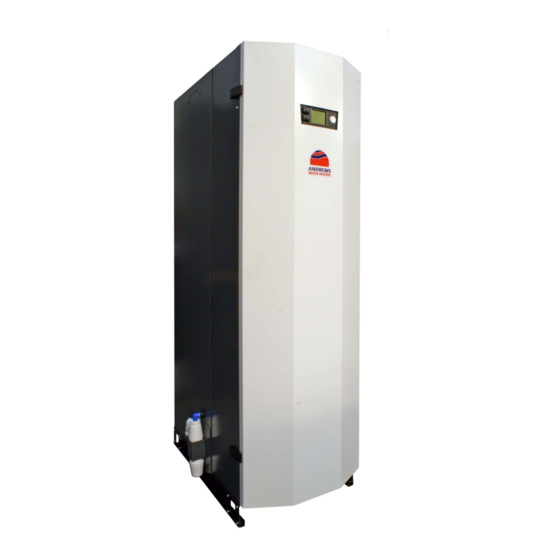
andrews MAXXflo EVO CWH 90/302 Installation And Maintenance Manual
High efficiency condensing stainless steel storage water heater
Hide thumbs
Also See for MAXXflo EVO CWH 90/302:
- Installation and maintenance manual (76 pages) ,
- Operating instructions manual (48 pages) ,
- Installation and maintenance manual (84 pages)
Table of Contents
Advertisement
INSTALLATION AND MAINTENANCE MANUAL
MAXXflo EVO
High efficiency condensing stainless steel storage water heater
CWH 90/302, CWH 120/302
Please read and understand these instructions before commencing installation and leave this manual with the customer for future reference.
Andrews. Built to perform.
M9373
Advertisement
Table of Contents

Subscribe to Our Youtube Channel
Related Manuals for andrews MAXXflo EVO CWH 90/302


Summary of Contents for andrews MAXXflo EVO CWH 90/302
- Page 1 INSTALLATION AND MAINTENANCE MANUAL MAXXflo EVO High efficiency condensing stainless steel storage water heater CWH 90/302, CWH 120/302 Please read and understand these instructions before commencing installation and leave this manual with the customer for future reference. Andrews. Built to perform. M9373...
- Page 2 Blank Page General MAXXflo EVO...
-
Page 3: Table Of Contents
Table of Contents Subject Page General & Safety Information Description of heater ................For whom is this manual intended? ............Symbols used in this guide ..............Safety General safety ..................Regulations and standards ..............UKCA & CE Marking ................Technical Data Technical data .................. -
Page 4: General & Safety Information
1.0 GENERAL & SAFETy INFORMATION 1.1 DESCRIPTION OF HEATER This Andrews Water Heaters MAXXflo EVO is a gas fired, low NOx, twin heat engine, cascading, direct fired water heater, with an integrated stainless steel tank. Fully automatic electronic controls are integrated into the heater, with a wide range of control and sensor options available. -
Page 5: Symbols Used In This Guide
1.3 SyMbOLS uSED IN THIS GuIDE DANGER! Indicates serious danger to personal safety and life DANGER of electric shock! Indicates serious danger from electricity to personal safety and life WARNING! Very hot water can cause severe burns and in extreme cases death CAUTION! Indicates a potentially dangerous situation for the heater and the environment... -
Page 6: Safety
This heater is designed to be used in a domestic hot water supply and storage system. Any other use of this heater will be considered improper. Andrews Water Heat- ers declines any responsibility for any damage or injuries caused by an improper use. In order to use the heater according to its designed scope, it is essential to carefully follow the instructions given in this guide. -
Page 7: Regulations And Standards
CAuTION If the water system is not in use for periods exceeding 14 days, there is an increased risk of corrosion on all copper parts and an increase in bacterial growth. Follow the recognised measures for Anti-legionella in section 5.4.2. to manage this risk 2.2 REGuLATIONS AND STANDARDS This heater must be installed in accordance with relevant Standard Specifications, Codes of Practice and cur- rent Building Regulations, together with any special regional requirements of the Local Authorities, Gas under-... -
Page 8: Ukca & Ce Marking
2.3 uKCA & CE MARKING There is one data plate located on the heater. This is mounted on the outside of the heater (left hand side) Type approval designation Gas type and pressure Model Name Heat, gas flow & CO data ²... -
Page 9: Technical Data
3.0 TECHNICAL DATA 3.1 TECHNICAL DATA Technical Data MAXXflo EVO... -
Page 10: Product Fiche
3.2 PRODuCT FICHE Technical Data MAXXflo EVO... -
Page 11: Performance Data
3.3 PERFORMANCE DATA PERFORMANCE Unit 90/302 120/302 Q Maximum Heat Input net (gross) 84.0 (93.3) 112.0 (124.4) Q Minimum Heat Input net (gross) 18 (19.5) 24 (26) Output Max (Min) 91.6 (19.5) 122.1 (26) V Maximum Gas Consumption G20 / G31 8.7 / 3.5 11.6 / 4.7 Flue gas temperature max (75... -
Page 12: General Dimensions And Connections
MAXXflo EVO CWH 30/301 CONCENTRIC FLUE/AIR 30kW & 60kW Models - 80mm/125mm MAXXflo EVO CWH 60/301 90kW & 120kW Models - 130mm/200mm 1.5" BSP (m) MAXXflo EVO CWH 90/302 MAXXflo EVO CWH 120/302 REMOVABLE AIR DUCT SPIGOT PLATE MULTIPLE CABLE ENTRY POINT... -
Page 13: System Schematic Examples
3.5 SySTEM SCHEMATIC EXAMPLES EXAMPLE 1: SINGLE MAXXflo EVO (SCHEMATIC) Maximum circulation rate Q4 pump Maximum ci Model MAXXflo MAXXflo EVO 90 EVO 120 Flow m EXAMPLE 2: PARALLEL MAXXflo EVO (SCHEMATIC) Technical Data MAXXflo EVO... - Page 14 3.5 SySTEM SCHEMATIC EXAMPLES (CONTINuED) EXAMPLES 1 & 2: SINGLE AND PARALLEL MAXXflo EVO (SETuP) 1 2 3 4 L N PE L N 5 6 7 8 Related settings table Menu Parameter Settings 1660 Set desired option for activation of the DHW circulation pump, normally either activated with Pump release time program 4 (DHW) or independently of DHW via time program 5 1661...
- Page 15 3.5 SySTEM SCHEMATIC EXAMPLES (CONTINuED) EXAMPLE 3: MAXXflo EVO & buFFER SS300-10 (SCHEMATIC) Technical Data MAXXflo EVO...
- Page 16 3.5 SySTEM SCHEMATIC EXAMPLES (CONTINuED) EXAMPLE 3: MAXXFLO EVO & STORAGE TANK (SCHEMATIC) Br Be L N PE L N 1 2 3 4 5 6 7 8 Related settings table (in addition to example 1 table) Menu Parameter Settings Configuration 6020 Set function of extension module 1 to “Multifunctional”...
- Page 17 3.5 SySTEM SCHEMATIC EXAMPLES (CONTINuED) EXAMPLE 4: bMS CONNECTIONS Modbus Enable Fault Flame Burner 1 Flame Burner 2 L N PE L N 1 2 3 4 5 6 7 8 Technical Data MAXXflo EVO...
-
Page 18: Wiring Diagrams
Wiring diagram - MAXXflo EVO Wiring diagram - MAXXflo EVO Master (Models 90 & 120 kW) 3.6 wIRING DIAGRAMS (MAXXflo EVO 90 & 120 Kw MODELS) Master (Models 90 & 120 kW) Wiring diagram - MAXXflo EVO Master (Models 90 & 120 kW) PCb1 L N PE L N 1 2 3 4... - Page 19 ng diagram - MAXXflo EVO ster (Models 90 & 120 kW) 3.6 wIRING DIAGRAMS (MAXXflo EVO 90 & 120) PCb2 Wiring Diagram - MAXXflo EVO Slave (Models 90 & 120 kW) 5 6 7 8 Technical Data MAXXflo EVO...
-
Page 20: Installation
4.0 INSTALLATION 4.1 LOCATING THE HEATER The location selected for installation of the heater must allow the provision of a satisfactory flue, an ad- equate air supply (for type B ), a drain and be well illuminated. A purpose built plant room or compartment is strongly recommended. - Page 21 Remove the four screws either side of the GUI display unit at high level. Loosen the two screws at low level inside the case to remove the case retaining bracket. Pull the inner cover forwards and remove completely. Case retaining bracket Installation MAXXflo EVO...
-
Page 22: Cold Water Supply
The MAXXflo EVO range of storage water heaters are designed to operate from a mains fed unvented water supply. An unvented system kit is available from Andrews Water Heaters. However, the heater may be connect- ed to an open vent supply provided the minimum supply pressure of 0.8 bar are maintained at all times. -
Page 23: Unvented Design
4.4 uNVENTED DESIGN DANGER Unvented systems should only be fitted by an approved installer When using the heater on an unvented hot water storage system, the Unvented System Kit, part number 7726954, available from the manufacturer must be fitted. When used in an unvented system, the heater will supply hot water at a maximum of 6 bar or at the pressure available at the mains feed if this is lower. -
Page 24: Secondary Return Design (Dhw Circulation Pump)
4.5 SECONDARy RETuRN DESIGN (DHw CIRCuLATION PuMP) A Secondary Return circuit may be fitted to the 1” nipple at the top of the heater. In all cases, for serviceability, the recirculation pipe must be fitted with a stop valve immediately before the connection point. See Section 3.6 Example 1 for wiring details If a secondary return circuit is fitted with a secondary pump, please ensure that the flow-rate does not exceed the heater maximum flow-rate, An excessive flow in the secondary circuit could result in a temperature mixing... -
Page 25: Condensate Disposal
4.6 CONDENSATE DISPOSAL Condensation is formed in the normal operation of the heater and this must be continuously discharged into a drain. Given the acidity level of condense discharge (pH 3.5 - 4.5) only plastic material can be used for the discharge pipe work. -
Page 26: Flue Systems And Ventilation
4.7.2 SuITAbLE FLuE MATERIAL When using a flue system that has not been supplied by Andrews Water Heaters, make sure that they are certified for the type and use. Check the text string printed on the flue system to ensure the correct materials are selected. - Page 27 4.7.3 GENERAL VENTILATION REQuIREMENTS (TyPE b CLASSIFICATION) DANGER Flue type B - Is an open flue appliance where air is drawn from the room or compartment in which the heater is installed and therefore the room or compartment must be ventilated to out- side air.
- Page 28 4.7.5 OPEN FLuE APPLIANCE IN A ENCLOSuRE VENTILATED DIRECT TO OuTSIDE AIR Installations within a compartment ventilated directly to outside air must be ventilated at high and low level. The minimum free area of permanently open vents must be as follows:- Minimum free vent area Heater Model Low level...
- Page 29 4.7.7 FLuE TERMINAL POSITIONS - b TyPE (OPEN FLuE) Terminals should be so positioned as to avoid products of combustion entering openings into buildings or other flues or vents Code Minimum distance (mm) MAXXflo MAXXflo EVO 90 EVO 120 2500 Directly below an opening, air brick, opening window etc Above an opening, air brick, opening window etc 1640...
- Page 30 4.7.8 ROOM SEALED FLuE (C & C ) SySTEM There are four approved room sealed arrangements where both the air inlet and flue discharge terminate out- side the building. Flue and air ducts are supplied to a concentric design using 130/200mm flue. See section 4.7.10 for compo- nent choices.
- Page 31 4.7.10 MAXXflo EVO 90 & 120 Kw FLuE PARTS Part number: Flue Kits - Description 7620229 VERT FLUE KIT CWH EVO 90 120 7620230 HORIZ FLUE TERM CWH EVO 90 120 Part number: Optional Flue Parts - Description 7620232 90˚ ELBOW C/W CLAMP 130/200 7620233 FLUE CONDENSE TRAP PP 130/200 7726992...
- Page 32 For maximum flue lengths see Minimum clearance section 4.8 between vertical Over 5.0m use flue condense trap terminals (see item L section 4.7.13) FLAT ROOF FLASHING E217 For maximum flue lengths see For maximum section 4.8 flue lengths see section 4.8 ANGLED ROOF FLASHING...
- Page 33 4.7.12 MAXXflo EVO 90 & 120 Kw FLuE SySTEM DIMENSIONS ALL Ø130/200mm CONCENTRIC FLuE FLUE CONDENSE TRAP VERTICAL FLUE TERMINAL CONDENSE TRAP PART No 7620233 C/W CLAMP PART No E211 PART No 7620229 Ø200 Ø32 Ø40 Ø130 Ø198/199 1780 45 ELBOW C/W CLAMP 90 ELBOW C/W CLAMP PART No 7726992 PART No 7620232...
- Page 34 4.7.13 FLuE TERMINAL POSITIONS - C TyPE (CONCENTRIC / TwIN) Terminals should be so positioned as to avoid products of combustion entering openings into buildings or other flues or vents Code Minimum distance (mm) Model CwH90 CwH120 2500 Directly below an opening, air brick, opening window etc Above an opening, air brick, opening window etc Horizontally to an opening, air brick, opening window etc Below gutters, soil pipes or drainpipes...
-
Page 35: Maximum Flue Lengths
4.8 MAXIMuM FLuE EQuIVALENT LENGTHS Permitted Flue Equivalent Length (FEL) for type b flue 44 metres Permitted Flue Equivalent Length (FEL) for type C flue 24 metres Permitted Flue Equivalent Length (FEL) for type C flue 48 metres The flue duct can discharge either vertically or horizontally by selection of the correct flue terminal. The flue system can be fitted with 90 and 45 bends, as well as extensions. -
Page 36: Gas Connections
4.9 GAS CONNECTIONS 4.9.1 GAS SuPPLy The installation of the gas supply must conform, to the Standards and Codes of Practice listed in Section 2.3 of this manual. This water heater is intended to be installed only on a gas supply with a governed meter. The gas meter, regulator and supply pipework must be sized so as to provide an adequate supply to the heater in addition to any other appliances connected to the supply (see 3.3 for gas consumption rates). -
Page 37: Electrical & Communication Connections
4.10 ELECTRICAL & COMMuNICATION CONNECTIONS DANGER This heater must be earthed DANGER Isolate the mains electrical supply to the heater before starting any work and observe all relevant safety precautions External wiring to the heater must be installed in accordance with current Regulations for the wiring of buildings and to any Local Regulations that may apply. - Page 38 (Boiler System Bus) - Is the communication system of the water heater, which is used to send and re- ceive information from the other controllers (if fitted) and can be used by the optional OZW672 Web Server, to provide access to the heater via the internet or mobile phone app. Please contact Andrews Water Heaters for further advice.
-
Page 39: Commissioning
5.0 COMMISSIONING GENERAL After installation of pipe work and fittings the water systems can then be filled and evacuated of all air before commencing commissioning. This is best done with the door and outer cover removed (see 4.2 for details) 5.1 FILLING AND REMOVAL OF AIR 5.1.1 DHw TANK AND SySTEM In order to ensure safe removal of air from the hot water system, please perform the following:... -
Page 40: Commissioning Of Heat Engine
5.2 COMMISSIONING THE HEAT ENGINES 5.2.1 IMPORTANT NOTES CAuTION The gas mixture and burner off-set gas rate (minimum load rate) is preset by the manufacturer. Please DO NOT attempt to change the settings of the off-set governor behind the sealed cover. Off-set governor cover DO NOT REMOVE DO NOT ADJUST... - Page 41 • Use the control thumb wheel to select “Setup” page and press the thumb wheel to select “Special operations” (see below) Regional settings Special operations Expert • Use the thumb wheel to select the “Chimney sweep” function and use the thumb wheel to activate this function.
- Page 42 If you are experiencing CO readings that exceed 200 ppm after 20 minutes of burner operation, please first check that your gas analyser is functioning correctly and then contact Andrews Water Heaters on the customer support number given on the rear cover of this manual, for advice.
- Page 43 If the Commissioning controller is not used the following commissioning procedure must be followed: • Set the time and date Using the GUI screen Refer to section 5.1 in the “CONTROLS OPERATING INSTRUCTIONS MANUAL” • Set the DHW heating times for daytime use using the GUI screen Refer to section 3.3 in the “CONTROLS OPERATING INSTRUCTIONS MANUAL”...
- Page 44 If you are experiencing CO readings that exceed 200ppm after 20 minutes of burner operation, please first check that your gas analyser is functioning correctly and then contact Andrews Water Heaters on the customer support number given on the rear cover of this manual, for advice.
- Page 45 5.2.4 HEAT ENGINE COMMISSIONING COMPLETION • Refit fan PWM connector onto the top heat exchanger, then press the RESET toggle switch for 1 second to clear the control lockout. • Once the lockout has been cleared from the display (bell symbol is not being displayed) close the door of the heater and secure it with the two door clips.
-
Page 46: Conversion To Lpg
5.3 CONVERSION FROM SECOND FAMILy (NATuRAL GAS - G20) TO THIRD FAMILy OF GASES (PROPANE - G31) This water heater is supplied from the factory already set up for G20 Natural Gas, but each heater can be converted on site to operate on Liquefied Propane Gas (G31). CAuTION This conversion must be carried out by a competent qualified person using only the parts provided by the manufacturer. - Page 47 CAuTION Please ensure that the cork gasket between the fan and the venturi is correctly placed before fixing with the two venturi screws. Place a screw through the venturi to hold the gasket in place when refitting to fan (see illustration below) •...
-
Page 48: Frost Protection And Legionella
5.4 FROST PROTECTION & LEGIONELLA 5.4.1 FROST PROTECTION The Heater is fitted with automatic Frost Protection. Provided there is mains power, gas connected and the heater is not in a lockout condition, if the temperature registered by the DHW tank temperature sensor falls below 5°C the heat engine will ignite to bring DHW tank temperature up to 6°C before turning off again. - Page 49 Menu for Anti-legionella function Line no Description Factory default Notes 1640 Legionella Function Choose to have the legionella function activated on a fixed weekday (parameter 1642), every (parameter 1641) number of days or switch the function off. 1641 Legionella function periodically 7 days No of days before the legionella function will activate 1642...
-
Page 50: Final Checks And User Handover
5.5 FINAL CHECKS & uSER HANDOVER 5.5.1 SETTING THE TIME CLOCK AND DHw TIME PROGRAM NB. The DHW time clock is factory programmed to optimise this heaters efficiency at the declared load profile under Eco-design Regulations. It is essential that the time / date is set correctly and the DHW operation times have been pro- grammed according to the requirements of the end user. -
Page 51: Fault Finding
5.6 FAuLT FINDING 5.6.1 OPERATION SEQuENCE To operate this heater you must have sufficient gas volume and be of the correct gas type. Electricity supply, 220-240v 50Hz and a valid demand from the DHW system. ALL MODELS 1. The circulation pump is turned on. 2. -
Page 52: Maintenance
6.0 MAINTENANCE DANGER In all cases, before work commences turn off the Mains Electricity and Gas Supply to the heater 6.1 ROuTINE INSPECTION INTERVALS AND REQuIREMENTS To ensure continued efficient operation of the heater it is recommended that it is checked and serv- iced at regular intervals. - Page 53 6.1.1.1 INSPECT AND CLEAN buRNER ASSEMbLy To view the burner and the inside of the heat exchanger it is recommended that you remove the front of the heat exchanger complete with the fan, venturi and gas valve. The following steps need to be completed before the combustion chamber and burner can be inspected:- •...
- Page 54 6.1.1.1 INSPECT AND CLEAN buRNER ASSEMbLy (CONT) Removed burner assembly Once assembly is free from the heat exchanger, carry out the following inspection: • Inspect the black silicone and rope gaskets on the inside of the heat exchanger door. Replace seals if there are any signs of damage and in any case replacement of the silicone gasket every two years is recommended.
- Page 55 • White vinegar can be used to remove stubborn deposits, by spraying the vinegar onto the coils and then waiting five minutes before scrubbing with a nylon brush and finally rinsing away all deposits with clean water, until the condense pipe runs clear. •...
- Page 56 6.1.1.2 SPARK ELECTRODE AND IONISATION ELECTRODE In order to maintain optimum reliability, it is recommended that both sets of electrodes are replaced every two years regardless of their condition. Both of these electrodes are best inspected when they are still in place and the entire heat exchanger door has been removed (see 6.1.1.1), but can also be inspected by carrying out the following : •...
- Page 57 6.1.1.4. CONDENSATE PIPEwORK AND SyPHON TRAP Inspect all joints in the condensate pipework for leaks The pipes themselves should be clear, flexible and no signs of any cracking should be visible. Investigate any white coloured areas anywhere on the condense pipe work. The lower bowl of the syphon should be unscrewed, examined and cleaned.
- Page 58 6.1.1.6 INSPECT AND FLuSH DHw STORAGE TANK The storage tank should be inspected annually and cleaned if required. To gain access for inspection please carry out the following procedure: • Turn off the electrical supply to the appliance • Shut of the cold water supply to the tank •...
-
Page 59: Removing And Changing Components
6.2 REMOVING AND CHANGING COMPONENTS DANGER NONE OF THE CONTROLS ARE REPAIRABLE . IF THEY ARE NOT FUNCTIONING THEY MUST BE REPLACED In all cases, before work commences turn off the mains electricity and gas supply. The following items do not require isolating water before removal: 1. - Page 60 6.2.2 FLuE TEMPERATuRE SENSOR (b8) This is located at the Flue outlet of the heat exchanger. • Unplug the sensor from the loom (squeeze the catch to release). Connector Flue sensor • Remove sensor by unscrewing anti-clockwise • Replacement is the reverse. 6.2.3 COMMON FLOw TEMPERATuRE SENSOR (b10) This is located on the top left hand side of the case, to the left of the top control PCB •...
- Page 61 6.2.5 LMS14 PCb MASTER & SLAVE REPLACEMENT ATTENTION Electrostatic sensitive PCB - Handle PCB by edges only and if available wear an earth wristband This is located on the bridge. It is important that the correct PCB replacement is used. Check that the model matches the replacement PCB •...
- Page 62 6.2.6 SPARK GENERATOR • Remove the power connections • Remove the ignition cable • Remove the 2 fixing screws Fixing screws Power connections: White = 1 Red = 2 • Replacement is the reverse 6.2.7 COMbuSTION FAN The combustion fan is best removed when the whole burner assembly has been detached from the heat ex- changer (see 6.1.1.1), but can also be removed individually if these steps are followed: •...
- Page 63 6.2.8 GAS VALVE • Turn off the gas supply at the burner gas cock isolator • Electrical connectors 4 x securing bolts Offset tube connector • Carefully remove the electrical connectors of the gas valve • Remove the allen bolts securing the gas pipe to the valve •...
- Page 64 6.2.10 bACK FLOw PREVENTION VALVE • Remove the 8 Torx screws holding the cover plate onto the air arm and gently pull cover away from the seal. • The Back Flow Prevention Valve (BFPV) is located inside the cover itself and can be slid out for inspection. •...
- Page 65 CAuTION Changing the following components will require some draining of the water system. It is essential that all the air is removed from the heat exchanger before the heater is operated. To not do so may damage the heat exchanger and invalidate the warranty. 6.2.13 HEAT EXCHANGER •...
- Page 66 • Remove the 6 heat exchanger door bolts and remove the whole burner assembly and put to one side. Removed burner assembly • Unscrew the flow and return pipework from the heat exchanger. • Unscrew the flow and return sensors form the heat exchanger and retain •...
- Page 67 6.2.14 CIRCuLATION PuMP Q1 • Close the shut off valve before and after the pump. • Use the drain points between the shut off valves to remove water from the pump • Remove the PWM and power connectors, using a small flat blade screwdriver to lift the white tab before pulling each connector free.
- Page 68 6.2.15 wATER PRESSuRE SENSOR • Close both water shut off valves and use one of the drain points to drain down water until no further release of water occurs • Carefully remove wiring connector from the sensor - using a small screwdriver to gently lift the tabs on each side in turn whilst at the same time gently pulling on the connector Pull connector away from sensor...
-
Page 69: Flushing/Descaling The Heat Exchangers
6.3 FLuSHING/DESCALING THE HEAT EXCHANGERS The following instructions only apply when the optional pressure sensor and isolation pipe work is fitted • Start by removing the B8 flue sensor connection (see 6.2.2) from the heat exchanger to be flushed and wait two minutes for the pump to stop rotating before turning off the heat engine isolation valves. -
Page 70: Component Parts Illustrations
6.4 COMPONENT ILLuSTRATIONS TANK & SuNDRy SPARES 104b 106b Item No. Description Part Number RETURN SENSOR KIT 7720071 OPTION - ANTI VAC VALVE 7709364 AIR VENT 1/2” 7617084 28x28x1/2” COMPRESSION TEE 7709367 104b 300 LITRE ACCESS HATCH ASSY INC O-RING 7720064 TEMP SENSOR DHW TANK B3 7709329... - Page 71 6.4 COMPONENT ILLuSTRATIONS INNER COVER & DOOR SPARES 203b 200b 204b Item No. Description Part Number 200b DOOR FOR MAxxflo EVO 300L 7725797 DOOR CLOSING LATCH SET 7709375 DOOR HINGE SET 7709376 203b DOOR GASKET MAxxflo EVO 300L 7709378 204b INNER COVER MAXXflo EVO 300L 7709380 INNER COVER FIXING SCREWS...
- Page 72 6.4 COMPONENT ILLuSTRATIONS (CONTINuED) GENERAL COMPONENTS Item No. Description Part Number CABLE GLAND 7709386 SPARK GENERATOR 7709314 LEAD FOR SPARK ELECTRODE 7709313 PRESS. SENSOR WATER H3 7709328 22MM RIGID FAN GAS COCK 7709371 NON-RETURN VALVE ASSY 7709287 PUMP FOR MAxxflo EVO 7709310 PUMP / NRV GASKET 7720039...
- Page 73 6.4 COMPONENTS ILLuSTRATIONS (CONTINuED) DRAIN COMPONENTS FLuE COMPONENTS Item No. Description Part Number CONDENSATE SYSTEM TWIN H/E 7709359 FLUE SYSTEM TWIN H/E MAxxflo EVO 7709361 FLUE SEAL SET TWIN H/E MAxxflo EVO 7709363 REMOVABLE 200MM AIR DUCT PLATE ASSY 7776499 Maintenance MAXXflo EVO...
- Page 74 6.4 COMPONENTS ILLuSTRATIONS (CONTINuED) HEAT ENGINE SPARES 506a 506b 509a 509b 509c 516a 516b 520a 520b 520c Maintenance MAXXflo EVO...
- Page 75 6.4 COMPONENTS ILLuSTRATIONS (CONTINuED) HEAT ENGINE SPARES (CONTINuED) Item No. Description Part Number TEMP. SENSOR FLOW RETURN B2/B7 7709317 TEMP. SENSOR FLUE B8 7709318 H/E SILICONE DOOR SEAL 7709294 H/E ROPE DOOR SEAL 7709295 H/E BURNER DOOR ASSY 7720060 H/E NUT SET FOR BURNER DOOR 7709297 506a BURNER FOR 30+45KW H/E...
- Page 76 6.4 COMPONENTS ILLuSTRATIONS (CONTINuED) wIRING CENTRE SPARES 603c 603d 605b SLAVE SPARES 611a 611b Item No. Description Part Number OCI345 COMMUNIC. DEV. C/W CABLE 7709285 MODBUS CLIP-IN MODULE KIT 7720069 OPTION - CLIP IN ExPANSION MODULE KIT 7720070 603c CONTROL PCB FOR MAxxflo EVO 90 7709321 603d CONTROL PCB FOR MAxxflo EVO 120...
- Page 77 6.4 COMPONENTS ILLuSTRATIONS (CONTINuED) COPPER PIPEwORK SPARES 802a 802b 805a 805b 807b 807a 809a 809b Item No. Description Part Number PIPE TWIN H/E GAS MANIFOLD 22 7709357 PIPE TANK CONN. FLOW ASSY 28 7709351 802a PIPE UP. 30&45KW H/E GAS 22MM 7709352 802b PIPE UP.
-
Page 78: Recommended Spares Requirements
6.5 RECOMMENDED SPARES REQuIREMENTS Emergency parts recommended to be kept on site The following components are recommended to ensure fast recovery times in the event of a heater compo- nent failure. An engineer attending a breakdown on site can immediately use the contents of the 1st aid kit to make a rapid repair. -
Page 79: Error Codes
6.6 ERROR CODES Error Error Code Description Diag. Notes Code Code Boiler temperature 1, sensor Other Boiler flow sensor (B2) is outside normal limits error Boiler flow sensor (B2) is short-circuit Boiler flow sensor (B2) is open-circuit Common flow temperature Check connections or replace faulty sensor located on com- sensor error mon flow pipe work up stand section (B10) - Page 80 6.6 ERROR CODES (CONTINuED) Error Error Code Description Diag. Notes Code Code SLT Lockout 306 431 Electronic temperature limits exceeded. General overheating 432 433 issue. Check for pump operation, trapped air and heat ex- 434 435 changer blockages. Monitor temperatures of system to estab- 436 756 lish problem area.
- Page 81 6.6 ERROR CODES (CONTINuED) Error Error Code Description Diag. Notes Code Code Flue gas temperature too high Any Check causes of high temperatures before operating Appliance. Inspect inside of heat exchanger for dirt build up. Check CO levels at min and max output. Safety time exceeded Records individual ignition failures and the times they have occurred.
- Page 82 6.6 ERROR CODES (CONTINuED) Error Error Code Description Diag. Notes Code Code Mains frequency outside per- Check electrical supply to appliance. mitted range Water press 3 too high Water pressure inside the appliance is too high for safe opera- tion. Operation will automatically resume once water pressure is at or below maximum levels.
- Page 83 SENSOR RESISTANCE VALuES NTC 10K Sensors (all sensors except for flue sensor): Temperature Resistance Temperature Resistance (Ohms) (Ohms) 32555 2989 25339 2490 19873 2084 15699 1753 12488 1481 10000 1256 8059 1070 6535 5330 3605 NTC 20K Sensors (flue sensor only): Temperature Resistance Temperature...
- Page 84 Sales 0345 070 1055 Technical 0345 070 1057 Web andrewswaterheaters.co.uk January 2021 June 2019 Registered office address: Baxi Heating UK, Brooks House, Coventry Road, Warwick CV34 4LL Andrews. Built to perform. ALL TOGETHER BETTER BAXI HEATING COMMERCIAL BRANDS...
Need help?
Do you have a question about the MAXXflo EVO CWH 90/302 and is the answer not in the manual?
Questions and answers