Table of Contents
Advertisement
INSTALLATION AND MAINTENANCE MANUAL
MAXXfl o EVO
High effi ciency condensing stainless steel storage water heater
CWH 30/201, CWH30/301, CWH60/201, CWH60/301
Please read and understand these instructions before commencing installation and leave this manual with the customer for future reference.
Andrews. Built to perform.
M8670
Advertisement
Table of Contents

Subscribe to Our Youtube Channel
Related Manuals for andrews MAXXflo EVO Series


Summary of Contents for andrews MAXXflo EVO Series
- Page 1 MAXXfl o EVO High effi ciency condensing stainless steel storage water heater CWH 30/201, CWH30/301, CWH60/201, CWH60/301 Please read and understand these instructions before commencing installation and leave this manual with the customer for future reference. Andrews. Built to perform. M8670...
- Page 2 Blank Page General MAXXfl o EVO...
-
Page 3: Table Of Contents
Table of Contents Subject Page General & Safety Information Description of heater ................For whom is this manual intended? ............Symbols used in this guide ..............Safety Usage and competency ................General safety ..................Regulations and standards ..............CE Marking ....................Technical Data Technical data .................. -
Page 4: General & Safety Information
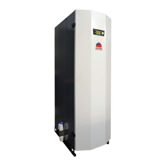
1.0 GENERAL & SAFETY INFORMATION 1.1 DESCRIPTION OF HEATER This Andrews Water Heaters MAXXfl o EVO is a gas fi red, low NOx, direct fi red water heater, with an integrated stainless steel tank. Fully automatic electronic controls are integrated into the heater, with a wide range of control and sensor options available. -
Page 5: Symbols Used In This Guide
1.3 SYMBOLS USED IN THIS GUIDE DANGER! Indicates serious danger to personal safety and life DANGER of electric shock! Indicates serious danger from electricity to personal safety and life WARNING! Very hot water can cause severe burns and in extreme cases death CAUTION! Indicates a potentially dangerous situation for the heater and the environment... -
Page 6: Safety
This heater is designed to be used in a domestic hot water supply and storage system. Any other use of this heater will be considered improper. Andrews Water Heat- ers declines any responsibility for any damage or injuries caused by an improper use. In order to use the heater according to its designed scope, it is essential to carefully follow the instruc- tions given in this guide. -
Page 7: Regulations And Standards
2.2.4 HEATER INSTALLATION AND MAINTENANCE This heater has been designed for use with G20 (natural gas) and G31 (liquefi ed propane gas) and is manufactured to give an effi cient, safe and long service life. To ensure continued trouble-free op- eration of this heater at maximum effi... -
Page 8: Ce Marking
2.4 CE MARKING There is one data plate located on the heater. This is mounted on the outside of the heater (left hand side) Type approval designation Gas type and pressure Model Name Heat, gas fl ow & CO data ²... -
Page 9: Technical Data
3.0 TECHNICAL DATA 3.1 TECHNICAL DATA SHEET Technical Data MAXXfl o EVO... -
Page 10: Product Fiche
3.2 PRODUCT FICHE Technical Data MAXXfl o EVO... -
Page 11: Performance Data
3.3 PERFORMANCE DATA PERFORMANCE Unit 30/201 30/301 60/201 60/301 Q Maximum Heat Input net (gross) 28.0 (31.1) 56.0 (62.2) Q Minimum Heat Input net (gross) 6.5 (7.2) 12 (13) Output Max (Min) 30.5 (7.1) 61.0 (13) V Maximum Gas Consumption G20 / G31 2.95 / 1.15 5.95 / 2.35 Flue gas temperature max (75... -
Page 12: General Dimensions And Connections
3.4 GENERAL DIMENSIONS & CONNECTIONS (200 LITRE MODELS) GAS INLET Model Dimensions: MANUAL INSPECTION 0.75" BSP BLEED VENT HATCH & SENSOR MAXXflo EVO CWH 30/201 WELL CONCENTRIC FLUE/AIR MAXXflo EVO CWH 60/201 80mm/125mm 1.5" BSP (m) REMOVABLE AIR DUCT SPIGOT PLATE MULTIPLE CABLE ENTRY POINT SECONDARY... - Page 13 3.4 GENERAL DIMENSIONS & CONNECTIONS (300 LITRE MODELS) MANUAL Model Dimensions: GAS INLET INSPECTION BLEED VENT 0.75" BSP HATCH & SENSOR WELL MAXXflo EVO CWH 30/301 CONCENTRIC FLUE/AIR 30kW & 60kW Models - 80mm/125mm MAXXflo EVO CWH 60/301 90kW & 120kW Models - 130mm/200mm 1.5"...
-
Page 14: System Schematic Examples
3.5 SYSTEM SCHEMATIC EXAMPLES EXAMPLE 1: SINGLE MAXXfl o EVO (SCHEMATIC) Maximum circulation rate Q4 pomp Model MAXXfl o MAXXfl o EVO 30 EVO 60 Flow (m EXAMPLE 2: PARALLEL MAXXfl o EVO (SCHEMATIC) Technical Data MAXXfl o EVO... - Page 15 3.5 SYSTEM SCHEMATIC EXAMPLES (CONTINUED) EXAMPLES 1 & 2: SINGLE AND PARALLEL MAXXfl o EVO (SETUP) (SUPPLIED BY OTHERS) L N PE L N 1 2 3 4 5 6 7 8 Parameter settings table: Menu Parameter Settings 1660 Set the desired option for activation of the circulation pump, normally activated with time Pump release program 4 (DHW) or independent of DHW via time program 5 1661...
- Page 16 3.5 SYSTEM SCHEMATIC EXAMPLES (CONTINUED) EXAMPLE 3: MAXXfl o EVO & BUFFER SS300-10 (SCHEMATIC) Technical Data MAXXfl o EVO...
- Page 17 3.5 SYSTEM SCHEMATIC EXAMPLES (CONTINUED) EXAMPLE 3: MAXXfl o EVO & STORAGE TANK (SCHEMATIC) Br Be L N PE L N 1 2 3 4 5 6 7 8 Parameter settings table (in addition to examples 1 & 2): Menu Parameter Settings Confi...
- Page 18 3.5 SYSTEM SCHEMATIC EXAMPLES (CONTINUED) EXAMPLE 4 : BMS CONNECTIONS Modbus Enable L N PE L N 1 2 3 4 5 6 7 8 Technical Data MAXXfl o EVO...
-
Page 19: Wiring Diagrams
3.6 WIRING DIAGRAMS (MAXXfl o EVO 30 & 60 KW MODELS) L N PE L N 1 2 3 4 5 6 7 8 Technical Data MAXXfl o EVO... -
Page 20: Installation
4.0 INSTALLATION 4.1 LOCATING THE HEATER The location selected for installation of the heater must allow the provision of a satisfactory fl ue, an ad- equate air supply (for type B ), a drain and be well illuminated. A purpose built plant room or compartment is strongly recommended. - Page 21 Remove the four screws either side of the GUI display unit at high level. Loosen the two screws at low level inside the case to remove the case retaining bracket. Pull the inner cover forwards and remove completely. Case retaining bracket Installation MAXXfl...
-
Page 22: Cold Water Supply
The MAXXfl o EVO range of storage water heaters are designed to operate from a mains fed unvented water supply. An unvented system kit is available from Andrews Water Heaters. However, the heater may be con- nected to an open vent supply provided minimum supply pressures are satisfi ed. -
Page 23: Unvented Design
4.4 UNVENTED DESIGN Unvented Systems should only be fi tted by an Approved Installer When using the Heater on an unvented hot water storage system, the Unvented System Kit, part number 7726954, available from the manufacturer must be fi tted. When used in an unvented system, the Heater will supply hot water at a maximum of 6 bar or at the pressure available at the mains feed if this is lower. -
Page 24: Secondary Return Design (Dhw Circulation Pump)
4.5 SECONDARY RETURN DESIGN (DHW CIRCULATION PUMP) A Secondary Return circuit may be fi tted to the 1” nipple at the top of the heater. In all cases, for serviceability, the recirculation pipe must be fi tted with a stop valve immediately before the connection point. If a secondary return circuit is fi... -
Page 25: Condensate Disposal
4.6 CONDENSATE DISPOSAL Condensation is formed in the normal operation of the heater and this must be continuously discharged into a drain. Given the acidity level of condense discharge (pH 3.5 - 4.5) only plastic material can be used for the discharge pipe work. -
Page 26: Flue Systems And Ventilation
4.7.2 SUITABLE FLUE MATERIAL When using a fl ue system that has not been supplied by Andrews Water Heaters, make sure that they are certifi ed for the type and use. Check the text string printed on the fl ue system to ensure the correct materials are selected. - Page 27 4.7.3 GENERAL VENTILATION REQUIREMENTS (TYPE B CLASSIFICATION) Flue type B - Is an open fl ue appliance where air is drawn from the room or compartment in which the heater is installed and therefore the room or compartment must be ventilated to out- side air.
- Page 28 4.7.5 OPEN FLUE APPLIANCE IN A COMPARTMENT VENTILATED VIA AN ADJOINING SPACE requirement 4.7.4 Where in addition to the previous requirement, the heater is to be installed within a compartment, ventilated via an adjoining room or space with connection to outside air, the compartment must be ventilated at high and low level.
- Page 29 4.7.7 FLUE TERMINAL POSITIONS - B TYPE (OPEN FLUE) Terminals should be so positioned as to avoid products of combustion entering openings into buildings or other fl ues or vents Code Minimum distance Directly below an opening, air brick, opening window etc Above an opening, air brick, opening window etc Horizontally to an opening, air brick, opening window etc Below gutters, soil pipes or drainpipes...
- Page 30 4.7.8 ROOM SEALED FLUE (C & C ) SYSTEM There are four approved room sealed arrangements where both the air inlet and fl ue discharge terminate out- side the building. Flue and air ducts are supplied to a concentric design and are 80/125mm fl ue size. See section 4.7.10 for component choices.
- Page 31 4.7.10 MAXXfl o EVO 30 & 60 KW FLUE PARTS Part number: Flue Kits - Description 5103917 VERT FLUE KIT CWH EVO 30, 60 PP 80/125 INC. SUPPORT BRACKET CLAMP & SEAL 7726957 HORIZ FLUE KIT CWH EVO 30, 60 HORIZ FLUE KIT PP 80/125 INC. ELBOW & WALL COVER PLATES Part number: Optional Flue Parts - Description 5136148 80/125 1 METER CUTABLE EXT.
- Page 32 For maximum fl ue lengths see section 4.8 Over 5.0m use fl ue condense trap Minimum clearance Condense between vertical terminals trap (see item L section 4.7.13) ANGLED ROOF For maximum FLASHING fl ue lengths see section 4.8 E066 FLAT ROOF FLASHING E065 Installation...
- Page 33 4.7.12 MAXXfl o EVO 30 & 60 KW FLUE SYSTEM DIMENSIONS ALL Ø80/125mm CONCENTRIC FLUE FLUE CONDENSE TRAP VERTICAL FLUE TERMINAL CONDENSE TRAP PART No 7726982 C/W CLAMP PART No E211 PART No 5103917 Ø32 Ø125 Ø40 Ø80 Ø123/124 1344 45 ELBOW C/W CLAMP 90 ELBOW C/W CLAMP PART No 5136151...
- Page 34 4.7.13 FLUE TERMINAL POSITIONS - C TYPE (CONCENTRIC / TWIN) Terminals should be so positioned as to avoid products of combustion entering openings into buildings or other fl ues or vents Code Minimum distance Directly below an opening, air brick, opening window etc Above an opening, air brick, opening window etc Horizontally to an opening, air brick, opening window etc Below gutters, soil pipes or drainpipes...
-
Page 35: Maximum Fl Ue Lengths
4.8 MAXIMUM FLUE LENGTHS Permitted Flue Equivalent Length (FEL) for type B fl ue 40 metres Permitted Flue Equivalent Length (FEL) for type C fl ue 18 metres Permitted Flue Equivalent Length (FEL) for type C fl ue 36 metres The fl... -
Page 36: Gas Connections
4.9 GAS CONNECTIONS 4.9.1 GAS SUPPLY The installation of the gas supply must conform, to the Standards and Codes of Practice listed in Section 2.3 of this manual. This water heater is intended to be installed only on a gas supply with a governed meter. The gas meter, regulator and supply pipework must be sized so as to provide an adequate supply to the heater in addition to any other appliances connected to the supply (see 3.3 for Maximum gas consumption rates). -
Page 37: Electrical & Communication Connections
4.10 ELECTRICAL & COMMUNICATION CONNECTIONS This heater must be earthed Isolate the mains electrical supply to the heater before starting any work and observe all relevant safety precautions External wiring to the heater must be installed in accordance with current Regulations for the wiring of buildings and to any Local Regulations that may apply. - Page 38 (if fi tted) and can be used by the optional Siemens OZW672 Web Server, to provide access to the heater via the Internet or mobile phone app. Please contact Andrews Water Heaters for further advice.
-
Page 39: Commissioning
5.0 COMMISSIONING GENERAL After installation of pipe work and fi ttings the water systems can then be fi lled and evacuated of all air before commencing commissioning. This is best done with the door and outer cover removed (see 4.2 for details) 5.1 FILLING AND REMOVAL OF AIR 5.1.1 DHW TANK AND SYSTEM In order to ensure safe removal of air from the hot water system, please perform the following:... -
Page 40: Commissioning The Heat Engine
5.2 COMMISSIONING THE HEAT ENGINE 5.2.1 IMPORTANT NOTES The gas mixture and burner off -set gas rate (minimum load rate) is preset by the manufacturer. Please DO NOT attempt to change the settings of the off -set governor behind the sealed cover. Off... - Page 41 • Use the control thumb wheel to select “Setup” page and press the thumb wheel to select “Special operations” (see below) Regional settings Special operations Expert • Use the thumb wheel to select the “Chimney sweep” function and use the thumb wheel to activate this function.
- Page 42 If you are experiencing CO readings that exceed 200 ppm after 30 minutes of burner operation, please fi rst check that your gas analyser is functioning correctly and then contact Andrews Water Heaters on the customer support number given on the rear cover of this manual, for advice.
-
Page 43: Conversion To Lpg
5.3 CONVERSION FROM SECOND FAMILY (NATURAL GAS - G20) TO THIRD FAMILY OF GASES (PROPANE - G31) This water heater is supplied from the factory already set up for G20 Natural Gas, but each heater can be converted on site to operate on Liquefi ed Propane Gas (G31). This conversion must be carried out by a competent qualifi... - Page 44 Please ensure that the cork gasket between the fan and the venturi is correctly placed before fi xing with the two venturi screws. Place a screw through the venturi to hold the gasket in place when refi tting to fan (see illustration below) •...
-
Page 45: Frost Protection And Legionella
5.4 FROST PROTECTION & LEGIONELLA 5.4.1 FROST PROTECTION The Heater is fi tted with automatic Frost Protection. Provided there is mains power, gas connected and the heater is not in a lockout condition, if the temperature registered by the DHW tank temperature sensor falls below 5°C the heat engine will ignite to bring DHW tank temperature up to 6°C before turning off... -
Page 46: Final Checks And User Handover
5.5 FINAL CHECKS & USER HANDOVER 5.5.1 SETTING THE TIME CLOCK AND DHW TIME PROGRAM NB. The DHW time clock is factory programmed to optimise this heaters effi ciency at the declared load profi le under Eco-design Regulations. It is essential that the time / date is set correctly and the DHW operation times have been programmed according to the requirements of the end user. -
Page 47: Fault Fi Nding
5.6 FAULT FINDING 5.6.1 OPERATION SEQUENCE To operate this heater you must have suffi cient gas volume and be of the correct gas type. Electricity supply, 220-240v 50Hz and a valid demand from the DHW system. 1. The circulation pump is turned on. 2. -
Page 48: Maintenance
6.0 MAINTENANCE IN ALL CASES, BEFORE WORK COMMENCES TURN OFF THE MAINS ELECTRICITY AND GAS SUPPLY TO THE HEATER 6.1 ROUTINE INSPECTION INTERVALS AND REQUIREMENTS To ensure continued effi cient operation of the heater it is recommended that it is checked and serv- iced at regular intervals. - Page 49 6.1.1.1 INSPECT AND CLEAN BURNER ASSEMBLY To view the burner and the inside of the heat exchanger it is recommended that you remove the front of the heat exchanger complete with the fan, venturi and gas valve. The following steps need to be completed before the combustion chamber and burner can be inspected:- •...
- Page 50 6.1.1.1 INSPECT AND CLEAN BURNER ASSEMBLY (CONT) Removed burner assembly Once assembly is free from the heat exchanger, carry out the following inspection: • Inspect the black silicone and rope gaskets on the inside of the heat exchanger door. Replace seals if there are any signs of damage and in any case replacement of the silicone gasket every two years is recommended.
- Page 51 • White vinegar can be used to remove stubborn deposits, by spraying the vinegar onto the coils and then waiting fi ve minutes before scrubbing with a nylon brush and fi nally rinsing away all deposits with clean water, until the condense pipe runs clear. •...
- Page 52 6.1.1.2 SPARK ELECTRODE AND IONISATION ELECTRODE In order to maintain optimum reliability, it is recommended that both sets of electrodes are replaced every two years regardless of their condition. Both of these electrodes are best inspected when they are still in place and the entire heat exchanger door has been removed (see 6.1.1.1), but can also be inspected by carrying out the following : •...
- Page 53 6.1.1.4. CONDENSATE PIPEWORK AND SYPHON TRAP Inspect all joints in the condensate pipework for leaks The pipes themselves should be clear, fl exible and no signs of any cracking should be visible. Investigate any white coloured areas anywhere on the condense pipe work. The lower bowl of the syphon should be unscrewed, examined and cleaned.
- Page 54 6.1.1.6 INSPECT AND FLUSH DHW STORAGE TANK The storage tank should be inspected annually and cleaned if required. To gain access for inspection please carry out the following procedure: • Turn off the electrical supply to the heater • Shut of the cold water supply to the tank •...
-
Page 55: Removing And Changing Components
6.2 REMOVING AND CHANGING COMPONENTS NONE OF THE CONTROLS ARE REPAIRABLE . IF THEY ARE NOT FUNCTIONING THEY MUST BE REPLACED In all cases, before work commences turn off the mains electricity and gas supply. The following items do not require isolating water before removal: •... - Page 56 6.2.2 FLUE TEMPERATURE SENSOR (B8) This is located at the Flue outlet of the heat exchanger. • Unplug the sensor from the loom (squeeze the catch to release). Connector Flue sensor • Remove sensor by unscrewing anti-clockwise • Replacement is the reverse. 6.2.3 AVS37 GUI DISPLAY This is located in the centre of the heater inside the front cover.
- Page 57 6.2.4 LMS14 PCB REPLACEMENT ATTENTION: Electrostatic sensitive PCB - Handle PCB by edges only and if available wear an earth wristband This is located on the bridge. It is important that the correct PCB replacement is used. Check that the model matches the replacement PCB •...
- Page 58 6.2.6 FAN The combustion fan is best removed when the whole burner assembly has been detached from the heat ex- The combustion fan is best removed when the whole burner assembly has been detached from the heat ex- changer (see 6.1.1.1), but can also be removed individually if these steps are followed: changer (see 6.1.1.1), but can also be removed individually if these steps are followed: •...
- Page 59 6.2.8 GAS VALVE • Turn off the gas supply at the burner gas cock isolator Electrical connectors 4 x securing bolts 4 4 4 4 4 Off set tube connector • Carefully remove the electrical connectors of the gas valve •...
- Page 60 6.2.10 BACK FLOW PREVENTION VALVE • Remove the 8 Torx screws holding the cover plate onto the air arm and gently pull cover away from the seal. • The Back Flow Prevention Valve (BFPV) is located inside the cover itself and can be slid out for inspection. •...
- Page 61 Changing the following components will require a partial draining of the water system. Once completed it is essential that all the air is removed from the heat ex- changer before the heater is operated. To not do so may damage the heat exchanger and invalidate the warranty.
- Page 62 • Remove the 6 heat exchanger door bolts and remove the whole burner assembly and put to one side. Removed burner assembly • Unscrew the fl ow and return pipework from the heat exchanger. • Unscrew the fl ow and return sensors form the heat exchanger and retain •...
-
Page 63: Component Parts Illustrations
6.3 COMPONENT ILLUSTRATIONS TANK & SUNDRY SPARES 104b 104a 106a 106b Item No. Description Part Number RETURN SENSOR KIT 7720071 OPTION - ANTI VAC VALVE 7709364 AIR VENT 1/2” 7617084 28X28X1/2” COMPRESSION TEE 7709367 104a 200 LITRE ACCESS HATCH ASSY INC O-RING 7720063 104b 300 LITRE ACCESS HATCH ASSY INC O-RING... - Page 64 6.3 COMPONENT ILLUSTRATIONS (CONTINUED) INNER COVER & DOOR SPARES 203a 203b 200a 200b 204a 204b Item No. Description Part Number 200a DOOR FOR MAXXfl o EVO 200L 7725796 200b DOOR FOR MAXXfl o EVO 300L 7725797 DOOR CLOSING LATCH SET 7709375 DOOR HINGE SET 7709376...
- Page 65 6.3 COMPONENT ILLUSTRATIONS (CONTINUED) GENERAL COMPONENTS Item No. Description Part Number CABLE GLAND 7709386 SPARK GENERATOR 7709314 LEAD FOR SPARK ELECTRODE 7709313 PRESS. SENSOR WATER H3 7709328 22MM RIGID FAN GAS COCK 7709371 NON-RETURN VALVE ASSY 7709287 PUMP FOR MAXXfl o EVO 7709310 PUMP / NRV GASKET 7720039...
- Page 66 6.3 COMPONENTS ILLUSTRATIONS (CONTINUED) DRAIN COMPONENTS FLUE COMPONENTS Item No. Description Part Number CONDENSATE SYSTEM SINGLE H/E 7709358 FLUE SYSTEM SINGLE H/E MAXXfl o EVO 7709360 FLUE SEAL SET SINGLE H/E MAXXfl o EVO 7709362 Maintenance MAXXfl o EVO...
- Page 67 6.3 COMPONENTS ILLUSTRATIONS (CONTINUED) HEAT ENGINE SPARES 506a 506b 509a 509b 509c 516a 516b 520a 520b 520c Maintenance MAXXfl o EVO...
- Page 68 6.3 COMPONENTS ILLUSTRATIONS (CONTINUED) HEAT ENGINE SPARES (CONTINUED) Item No. Description Part Number TEMP. SENSOR FLOW RETURN B2/B7 7709317 TEMP. SENSOR FLUE B8 7709318 H/E SILICONE DOOR SEAL 7709294 H/E ROPE DOOR SEAL 7709295 H/E BURNER DOOR ASSY 7720060 H/E NUT SET FOR BURNER DOOR 7709297 506a BURNER FOR 30+45KW H/E...
- Page 69 6.3 COMPONENTS ILLUSTRATIONS (CONTINUED) WIRING CENTRE SPARES 603a 603b 605a Item No. Description Part Number MODBUS CLIP-IN MODULE KIT 7720069 OPTION - CLIP IN EXPANSION MODULE KIT 7720070 603a CONTROL PCB FOR MAXXfl o EVO 30 7709319 603b CONTROL PCB FOR MAXXfl o EVO 60 7709320 CONTROL PCB FUSES (2 PACK) 7709324...
- Page 70 6.3 COMPONENTS ILLUSTRATIONS (CONTINUED) COPPER PIPEWORK SPARES - 201/301 MODELS 201/301 with door & inner cover removed 201/301 with components & panels removed for clarity 703a 703b 704a 704b 705a 705b Item No. Description Part Number PIPE TANK CONN. FLOW ASSY 28 7709351 PIPE SING.
-
Page 71: Recommended Spares Requirements
6.4 RECOMMENDED SPARES REQUIREMENTS Emergency parts recommended to be kept on site The following components are recommended to ensure fast recovery times in the event of a heater compo- nent failure. An engineer attending a breakdown on site can immediately use the contents of the 1st aid kit to make a rapid repair. -
Page 72: Error Codes
6.5 ERROR CODES Error Error Code Description Diag. Notes Code Code Boiler temperature 1, sensor Other Boiler fl ow sensor (B2) is outside normal limits error Boiler fl ow sensor (B2) is short-circuit Boiler fl ow sensor (B2) is open-circuit Common fl... - Page 73 6.5 ERROR CODES (CONTINUED) Error Error Code Description Diag. Notes Code Code SLT Lockout 306 431 Electronic temperature limits exceeded. General overheating 432 433 issue. Check for pump operation, trapped air and heat ex- 434 435 changer blockages. Monitor temperatures of system to estab- 436 756 lish problem area.
- Page 74 6.5 ERROR CODES (CONTINUED) Error Error Code Description Diag. Notes Code Code Flue gas temperature too high Any Check causes of high temperatures before operating Appliance. Inspect inside of heat exchanger for dirt build up. Check CO levels at min and max output. Safety time exceeded Records individual ignition failures and the times they have occurred.
- Page 75 6.5 ERROR CODES (CONTINUED) Error Error Code Description Diag. Notes Code Code Mains frequency outside per- Check electrical supply to appliance. mitted range Water press 3 too high Water pressure inside the appliance is too high for safe opera- tion. Operation will automatically resume once water pressure is at or below maximum levels.
- Page 76 Sales 0345 070 1055 Technical 0345 070 1057 Web andrewswaterheaters.co.uk July 2019 June 2019 Andrews. Built to perform. ALL TOGETHER BETTER BAXI HEATING COMMERCIAL BRANDS...
Need help?
Do you have a question about the MAXXflo EVO Series and is the answer not in the manual?
Questions and answers