Table of Contents
Advertisement
This manual must be kept with the appliance
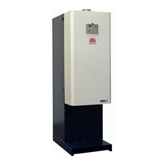
MAXXflo
In s ta lla tion g u id e , op e r a tion
a n d m a in te n a n c e m a n u a l
High Efficiency Condensing
S ta inless S teel S tora ge
W a ter Hea ters for
N a tu ra l G a s a nd P rop a ne
N a tu r a l G a s Mod e ls
CW H3 0 /1 0 0 , CW H3 0 /2 0 0 , CW H3 0 /3 0 0
CW H6 0 /2 0 0 , CW H6 0 /3 0 0
CW H9 0 /2 0 0 , CW H9 0 /3 0 0
CW H1 2 0 /2 0 0 , CW H1 2 0 /3 0 0
P r op a n e Mod e ls
L CW H3 0 /1 0 0 , L CW H3 0 /2 0 0 , L CW H3 0 /3 0 0
L CW H6 0 /2 0 0 , L CW H6 0 /3 0 0
L CW H9 0 /2 0 0 , L CW H9 0 /3 0 0
L CW H1 2 0 /2 0 0 , L CW H1 2 0 /3 0 0
Working towards
a c le ane r fu tu re
P a rt N o. E2 8 1
J a n 2 0 0 9
Advertisement
Table of Contents

Related Manuals for andrews CWH30/100


Summary of Contents for andrews CWH30/100
- Page 1 This manual must be kept with the appliance J a n 2 0 0 9 MAXXflo In s ta lla tion g u id e , op e r a tion a n d m a in te n a n c e m a n u a l High Efficiency Condensing S ta inless S teel S tora ge W a ter Hea ters for...
- Page 2 Health and S afety R egu lations 1 9 9 3 . All installation and serv ic e on the Andrews Water Heater m u st b e c arried ou t b y...
-
Page 3: Table Of Contents
CONTENTS PAGE SECTION 1 DESCRIPTION General Information British Standards Health and Safety Regulations 1993 Legionellae in Water Heaters SECTION 2 TECHNICAL DETAIL S Technical D etails - CWH30/ 60/ 90/ 120 Heater D imensions - 100 Litre M odel Heater D imensions - 200 Litre M odels Heater D imensions - 300 Litre M odels SECTION 3 INSTAL L ATION... -
Page 4: General Information
SECTION 1 GENERAL AND SAFETY INFORMATION GENERAL The Andrews Water Heater has been designed for use with NATURAL GAS or PROPANE and is manufactured to give an efficient, reliable and long service life. INFORMATION To ensure the continued, trouble-free operation of your heater at maximum efficiency, it is essential that correct installation, commissioning, operation and service procedures are carried out strictly in accordance with the instructions given in this manual. -
Page 5: Health And Safety Regulations 1993
Andrews Water Heaters should only be used in the manner and purpose for which they were intended and in accordance with the instructions in this manual. Although the heaters have been manufactured with paramount consideration to safety, certain basic precautions specified in this manual must be taken by the user. -
Page 6: Technical Details
SECTIO N 2 TECHNICAL DETAILS Model reference C W H 3 0 / 1 0 0 C W H 3 0 / 2 0 0 C W H 6 0 / 2 0 0 C W H 9 0 / 2 0 0 C W H 1 2 0 / 2 0 0 Model reference C W H 3 0 / 3 0 0... - Page 7 35mm DRAIN AC ESS C N ENSE T AP EA ER 3/4 GA IN ET E CAN BE " AT R S PPLY 1000 1" RE URN COLD IDEAL S RVICE 1 TUND SH UP LIED PLAN VIEW MODEL CWH30/100...
- Page 8 SECTION 2 TECHNICAL DETAILS H ater Dimensions Models CWH 0/200, CWH60/200, CWH90/200 and CWH120/200 NOTE:- See a es 18 to 26 for flue d tails Mo el CWH30 and 60 use 80/125mm diameter conce tri fl e components Models CWH90 and 120 use 130/200mm diameter oncentric flue components 35 m DR IN TO DRAIN...
- Page 9 TECHNICAL DETAILS SECTION 2 Heater Dimensions Mo e s CWH30/300, CWH60/300, CWH90/300 and CWH120/300 NOTE:- See a es 18 to 26 for flue details Mo els CWH30 and 60 use 80/125mm dia et r c nc nt ic lue components Models CWH90 and 120 use 130/200mm diameter conc ntr c flue components 35 m TO RAIN...
-
Page 10: Installation
SECTION 3 INSTALLATION series is a direct fired condensing storage water heater which has a DESCRIPTION stainless steel tank that is heated b y u p to fou r b u rner m odu les p laced ou tside the tank . A b u rner m odu le consists of a stainless steel heat ex changer in which the b u rner is p laced. -
Page 11: Location
INSTALLATION SECTION 3 TH E LAW REQ U IRES TH AT TH E INSTALLATION IS CARRIED OU T B Y A LOCATION PROPERLY Q U ALIF IED PERSON Installations must be carried out in accordance with G as safety (Installation and U se) R egulations 1 998 , Building R egulations, The Water S upply (Water F ittings) R egulations 1 999 and any requirements of the local G as Authority, L ocal Authority, Water and F ire Authorities and the current British S tandards and Codes of P ractice listed in S ection 1 . -
Page 12: Water Quality And Treatment
SECTION 3 INSTALLATION WATER When installing Andrews Water H eaters in hard water areas we would recommend that a water treatment specialist is consulted. QUALITY AND In hard water areas, scale formation can occur in all hot water systems and water heaters and the TREATM ENT higher the temperature and volume of water used, the more problematic the scale build-up can be. - Page 13 INSTALLATION SECTION 3 TYPICAL Tank cleaning INSTALLATION access Return Fig. 1a Return pump Mains feed unvented kit Flue Control panel Cold feed T&P relief Cover Cover valve removable removable for service for service Tundish Condense trap Condense drain CWH30 Tank drain CWH6 0 Fig.
-
Page 14: G As Supply Natural Gas
Systems: Design and installation plus the requirements of British Standards and Codes of Practice listed in Section of this manual. Andrews water heaters are unregulated and a second stage regulator must be installed to give an inlet pressure to the appliance as follows: (See fig. 2). -
Page 15: Typical Bulk Storagev Essel Installation
INSTALLATION SECTION 3 P le a s e e n s u re th a t th e g a s p ip e is s iz e d to p ro v id e a m in . o f 37 m b a r a t th e a p p lia n c e TYPICAL BULK G a s c o c k R e g u la to r S e t to g iv e a... -
Page 16: Electrical Supply
SECTION 3 INSTALLATION ELECTRICAL E x ternal wiring to the water heater(s) must be installed in accordance with current I.E .E . Regulations for the wiring of buildings and to any Local Regulations that may apply. SUPPLY range is designed to operate from a permanent 2 30 v/ 5 0 Hz single phasesupply. - Page 17 INSTALLATION SECTION 3 Fig. 5 Wiring d iagram. M ake sure that the phase (L) and the neutral (N) are connected to the correct terminals on the connector. The appliance is phase sensitive, swapping the phase and neutral will lead to a fault in the appliance.
- Page 18 SECTION 3 INSTALLATION TEMPORARY It is possible to change the water heater temperature remotely via a timer programme. First of all the new, desired water heater temperature is set at a value higher or lower WATER than the water heater temperature during normal operation. This makes it possible, for HEATER example, to carry out legionella flushing.
-
Page 19: Wiring Diagram
INSTALLATION SECTION 3 HWST TANK DIMENSIONS Fig. 7 Empty Weight HWST 200 120 kg HWST 300 140 kg WIRING DIAGRAM Fig. 8... -
Page 20: Flue Systems
The heater when fitted with a concentric flue system provides a room sealed application. The concentric flue, supplied by Andrews, is available for either horizontal or vertical installation and the table below shows the basic kit supplied plus optional extras. - Page 21 INSTALLATION SECTION 3 CWH30 & CWH60 Flue Systems The CWH30 & CWH60 uses a concentric flue system, 125mm outside diameter with an inner flue of 8 0mm diameter. Flue components fit together with silicon sealing rings and the flues are retained with sealing clamps.
- Page 22 SECTION 3 INSTALLATION CWH30 & CWH60 Alternative Flue Systems CWH30 max 50M Conventional CWH60 max 20M Conventional CWH30 max 14 M Concentric CWH60 max 12M Concentric O ver 1.5M use flue Condense trap. Minimum between Condense Tap V ertical terminals 300mm drain Minimum between balanced...
- Page 23 INSTALLATION SECTION 3 CWH30 & CWH60 Standard Flue System Dimensions ALL 80/125mm Ø CONCENTRIC FLU E Ø125 Ø80 Ø 123/124 COND ENSATE TRAP PART No E310 Ø80 45º ELBOW C/W CLAMP PART No E308 Ø80 VERTICAL FLU E TERMINAL C/W CLAMP (COND ENSING) PART No E067 90º...
- Page 24 SECTION 3 INSTALLATION CWH90 & CWH120 Flue Systems The CWH90 & CWH120 uses a concentric flue system, 200mm outside diameter w ith an in n er flue of 1 3 0mm diameter. Flue components fit together with silicon sealing rings and the flues are retained with sealing clamps.
- Page 25 INSTALLATION SECTION 3 CWH90 & CWH120 Alternative Flue Systems CWH90 max 50M Conventional CWH1 2 0 max 4 0M Conventional CWH90 and CWH1 2 0 max 1 4 M Concentric Minimum clearence Over 1.5M use flue between vertical condense trap. balanced flue terminals Condense Tap drain...
- Page 26 SECTION 3 INSTALLATION CWH90 & CWH120 Standard Flue System Dimensions AL L 130/ 200M M Ø C ON C E N T R IC F L U E Ø200 Ø130 Ø130 Ø 198/199 Ø 198/199 C ON D E N SAT E T R AP 4 5 º...
-
Page 27: Flue Systems - Cwh 30
INSTALLATION SECTION 3 Likely flue positions requiring a flue terminal guard Fig. 9 FLUE SYSTEMS Terminal Positions with Minimum Distance Directly below an opening, air brick, opening window etc. Above an opening, air brick, opening window etc. Horizontally to an opening, air brick, opening window etc. Below a gutter or sanitary pipework Below the eaves Below a balcony or carport roof... - Page 28 SECTION 3 INSTALLATION FLUE SYSTEMS Horizontal termination NOTE: (Room sealed or conventional flue) See page 25 for positioning of flue terminals. Vertical termination (Room sealed or conventional flue) Fig. 10...
- Page 29 INSTALLATION SECTION 3 The following notes are intended to give guidance: AIR SUPPLY Where the heater is to be installed in a room, NO VENTS ARE REQ UIRED. Where the heater is to be installed in a COMPARTMENT, permanent air vents are VENTILATION required in the COMPARTMENT at high and low level.
-
Page 30: Air Supply And V Entilation - Concentric Flue Systems
SECTION 3 INSTALLATION IMPORTANT: AIR SUPPLY 1. The effective area requirements specified in the table are related to the maximum heat input of of the heater(s), and are equivalent to those specified in BS6644. VENTILATION 2. The free area of the grilles should not be less than the size of the recommended CONCENTRIC ventilation opening. - Page 31 INSTALLATION SECTION 3 The minimum effective areas of the permanent air vents required in the AIR SUPPLY compartment are as follows;- VENTILATION Air Vent Areas Position of Air Vents Air from room or internal space Air direct from outside CONVENTIONAL Net input Net input High Level...
- Page 32 SECTION 3 INSTALLATION CWH HEAT The water heater is equipped with 1, 2, 3 EX CHANGER or 4 burner modules CONFIGURATION depending on the model. Each burner module has its own automatic burner. CWH 30 CWH 60 CWH 90 CWH 120 The operational status of the water heater can be seen and the desired temperature can CONTROL be set on the control panel (Fig.11).
-
Page 33: Instructions For Commissioning
INSTRUCTIONS FOR COMMISSIONING SECTION 4 The water heater temperature can be set between 40°C and 70°C using the + and - TEMPERATURE buttons on the control panel. The maximum temperature for the Legionella flushing SETTING programme is 75ºC. The lower the temperature the lower the chance of lime deposits (less maintenance). The risk of scalding is also less (think of children, those with special needs and the elderly). -
Page 34: Filling The Water Heater
SECTION 5 INSTRUCTIONS FOR COMMISSIONING 1. Check that the tank drain tap is closed. FILLING THE 2. Check that the return valve in the 28mm pipe (close to the drain tap) is open. WATER HEATER 3. Open the main water tap and then all warm water drainage points, so that air present in the installation and water heater can escape. -
Page 35: Control And Adjustment At Full Load
INSTRUCTIONS FOR COMMISSIONING SECTION 5 CONTROL 1. Switch the water heater off and flush system until the tank is completely cooled down. 2. Put the water heater in operation. ADJUSTMENT 3. Press the reset button down for longer than 5 seconds, L appears in the display. Pressing the reset button again, C00 appears in the display. -
Page 36: Control And Adjustment At Low Load
SECTION 5 INSTRUCTIONS FOR COMMISSIONING 1. Select low load with the - button. When the actual burner capacity is above 25% the CONTROL AND percentage can be measured and set. ADJUSTMENT AT LOW LOAD 2. Measure the CO percentage and check it against table 1 (page 32). The CO percentage can be adjusted using the ”Low Load”... -
Page 37: Fault Codes
FAULT CODES SECTION 6 A fault code will appear in the control panel display if there is a lockout failure. A letter and FAULT the number of the burner module appear alternately in the display. The letter A is for a CODES lockout fault, and E is for a blocking fault. -
Page 38: Maintenance
SECTION 7 MAINTENANCE At least once a year the following works must be carried out: 1. Check the CO percentage and adjust if necessary, see page 32. 2. Check the output at full load by measuring the gas usage. If this deviates more than 15% from the nominal value (see Section 2, Technical Details) then this is an indication of dirt or blockages in the flue gas extraction channel, the air supply channel or the condensation extractor. - Page 39 MAINTENANCE SECTION 7 The burner and exchanger do not normally need to be cleaned. If there is a suspicion of dirt then the exchanger should be opened on the bottom. New gaskets must always be used when assembling. The top of the exchanger must never be opened. The hot surface igniter is a vulnerable part that should only be removed if it has to be replaced.
-
Page 40: Parts List
SECTION 8 PARTS LIST SPARES LIST Parts Description Part Number Quantity FOR CWH Main Dungs Gas Valve Assembly E659 M1835 1 per module Main Gas Valve O R ing E84 5 M184 2 1 per module RANGE F an Assembly & Gask et E658 M1834 1 per module... - Page 41 Temperature/Pressure Relief Valve C380 1 – 30 & 60 kW C380 2 – 9 0 & 12 0 kW Andrews Dome Label E856 M1845 Maxxflo Dome Label E927 M2290 Front Cover (pump facing rear) E918 M1717 Pre serial number 071201...
- Page 42 MAINTENANCE S ECTIO N 7 Unvented Systems Kit Installation Details M ax x flo W ater H eater C W H 3 0 /6 0 /9 0 /1 2 0 R et u r n R e t u r n p u m p H W S G as Mains feed...
- Page 44 0087 S ales : 0845 070 1056 Andre ws Wa te r He a te rs Wood Lane, E rdington, B irmingham B 24 9QP Tec hnic al: E mail: andrews @baxigroup.c om 0845 070 1057 www.andrews waterheaters .c o.uk...
Need help?
Do you have a question about the CWH30/100 and is the answer not in the manual?
Questions and answers