Table of Contents
Advertisement
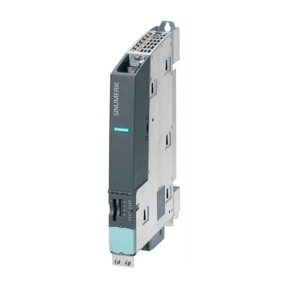
NCU 7x0.2
SINUMERIK
SINUMERIK 840D sl
NCU 7x0.2
Manual
Valid for
Control
SINUMERIK 840D sl / 840DE sl
Software
CNC software
02/2011
6FC5397-0AP20-0BA0
Version
2.7
___________________
Preface
___________________
Safety Information
___________________
System overview
___________________
Description
___________________
Application Planning
___________________
Dimension drawings
___________________
Mounting
___________________
Connecting
___________________
Technical Data
Connectable components
___________________
Spare Parts/Accessories
___________________
Appendix
1
2
3
4
5
6
7
8
9
10
A
Advertisement
Table of Contents


Need help?
Do you have a question about the NCU 7 0.2 Series and is the answer not in the manual?
Questions and answers