Advertisement
Quick Links
Advertisement

Related Manuals for ESX VN720 HY-iX35


Summary of Contents for ESX VN720 HY-iX35
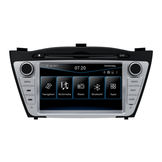
- Page 1 VN720 HY-iX35...
- Page 2 INSTALLATION NOTES / Installationshinweise Important Notes prior to installation: This guide is an installation aid for a proper installation of the device. Please read the following instructions prior installation: 1.) Please treat all parts of the sound system and the components of your vehicle with caution. 2.) Follow under all circumstance the regulations of the vehicle manufacturer and do not make any modifications on the vehicle, which could interfere the driving safety.
-
Page 3: Table Of Contents
INDEX / Inhaltsverzeichnis Scope of delivery ..........................4 Lieferumfang ............................4 Connection Diagram ........................... 6 Anschlussdiagramm ..........................6 Installation notes ..........................11 Installationshinweise .......................... 11 Installation example ......................... 13 Einbaubeispiel ............................ 13 Optional accessories: Optionales Zubehör: If applicable, an original Hyundai center console cover for iX35 facelift vehicles is needed. Ggf. -
Page 4: Scope Of Delivery
SCOPE OF DELIVERY / Lieferumfang ITEM FIGURE QUANTITY Artikel Abbildung Anzahl MAIN DEVICE Hauptgerät STYLUS Markierstift MICRO SD CARD 8GB INKL: NAVIGATION SOFTWARE MicroSD Speicherkarte 8GB Navigationssoftware REMOTE CONTROL Fernbedienung G71-AUD0119 AUDIO / VIDEO / AV INPUTS Audio / Video / AV-Eingänge G71-MNV0010 AUDIO OUTPUTS 5.1 WITH REMOTE TURN ON... -
Page 5: Lieferumfang
SCOPE OF DELIVERY / Lieferumfang ITEM FIGURE QUANTITY Artikel Abbildung Anzahl G71-CCD0057 CAMERA CONNECTIONS FOR ORIGINAL REARCAM Kamera-Anschlüsse für originale Rückfahrkamera G71-MNV0009 AUDIO/VIDEO OUTPUTS 1/2 Audio/Video-Ausgänge G71-USB0055 USB PORT WITH QUICK CHARGE FUNCTION USB-Anschluss mit Schnellldadefunktion GPS ANTENNA GPS Antenne TMC WIRE ANTENNA TMC Kabelantenne Y-ANTENNA ADAPTOR WITH 2,5 MM... -
Page 6: Connection Diagram
CONNECTION DIAGRAM / Anschlussdiagramm AM/FM ANTENNA AM/FM Antenne SPECIFIC CONNECTORS OF THE VEHICLE AUDIO / VIDEO / AV INPUTS Fahrzeugspezifische Stecker Audio / Video / AV-Eingänge AUDIO/VIDEO OUTPUTS Audio/Video-Ausgänge AUDIO OUTPUTS 5.1 WITH REMOTE TURN ON FUSE (10 A) Audio-Ausgänge 5.1 mit Einschaltleitung Gerätesicherung (10 A) CAMERA CONNECTIONS Kamera-Anschlüsse... -
Page 7: Anschlussdiagramm
ENGLISH IMPORTANT NOTE: Usually both OEM plugs of the vehicle must be connected („plug and play“) to the ESX Naviceiver, without the need to change the PIN configuration in any way. But please check the exact pin assignment, especially „ACC“, „BATT“ and „CANL / CANH“ of the original plug for its correctness. - Page 8 „REVERSE“ (blue cable). The „GND“ and „CCD POWER OUT“ cables must not be connected obligatorily. Now activate the „CCD-Camera“ check box under APPS -> OPTIONS -> DISPLAY at the ESX device. Operation note: When the reverse gear is engaged, the device does not allow any other operation, all the buttons and controller except volume control are blocked for security reasons.
- Page 9 CONNECTION DIAGRAM / Anschlussdiagramm DEUTSCH WICHTIGER HINWEIS: In der Regel werden die beiden OEM Stecker des Fahrzeugs „plug and play“ an den ESX Naviceiver ange- schlossen, ohne dass die PIN Belegung in irgendeiner Weise geändert werden muss. Prüfen Sie dennoch die exakte Pinbelegung, speziell „ACC“, „BATT“...
- Page 10 Dieser Ausgang ist nicht zur Stromversorgung einer Nachrüstkamera geeignet. FRONT CCD-POWER OUT rot 12V Ausgang für Stromversorgung einer Nachrüst-Frontkamera, max. 500mA. 12V werden ausgegeben, sobald das ESX Gerät in Betrieb ist. Stellen Sie sicher, dass Ihre Kamera für den Dauerbetrieb geeignet ist. schwarz Masseanschluss der Stromversorgung einer optionalen Kamera (Front u.
-
Page 11: Installation Notes
Innenraumleuchte anbringen. Vermeiden Sie das Verlegen des Kabels über die Lenksäule. In der Regel sollte das Kabel lang genug sein, um die A-Säule (Fahrerseite) über die Beifahrerseite zu erreichen. Ein evtl. werksseitig vorhan- denes Mikrofon ist nicht kompatibel mit dem ESX Gerät. -
Page 12: Installationshinweise
INSTALLATION NOTES / Installationshinweise Handbrake connection: The handbrake signal needs to be connected with the included cable (5, BRAKE IN). The signal must be connected to ground with the handbrake closed. Ple- ase contact for a correct and safe installation your automotive service center! Accordance to legal regulations the device must only playback a DVD or video may on the main screen only with the handbrake closed. -
Page 13: Installation Example
INSTALLATION EXAMPLE / Einbaubeispiel 1.) Loosen the lower panel with a mounting wedge on both sides. 1.) Lockern Sie die untere Blende mit einem Montagekeil auf beiden Seiten. 2.) Pull out the lower panel. 2.) Ziehen Sie die untere Blende vorsichtig heraus. 3.) Loosen now the upper panel above the radio with a mounting wedge on both sides. -
Page 14: Einbaubeispiel
Fahrzeugen müssen die beiliegenden Montagehalter (siehe Seite 5, # 15) verwendet werden. 7.) Lay the connection cable sets of new ESX device (refer to page 4-5) inside the vehicle to the desired location and connect these according with the sockets on the new ESX device. Plug in car specific and the antenna connectors. - Page 15 INSTALLATION EXAMPLE / Einbaubeispiel 9.) Before you complete the installation, make a function check. Please note that it may take up to 15 minutes, until a GPS signal can be received outside. ATTENTION: Before you start the function check and turn on the ignition, you must mandatorily reconnect the lower panel with the control lamps and switches.
- Page 16 ESX Car Media Systems · Audio Design GmbH Am Breilingsweg 3 · D-76709 Kronau/Germany Tel. +49 7253 - 9465-0 · Fax +49 7253 - 946510 www.esxnavi.de - www.audiodesign.de ©2017 All Rights Reserved...
Need help?
Do you have a question about the VN720 HY-iX35 and is the answer not in the manual?
Questions and answers