Table of Contents
Advertisement
FOREWORD
Notice
The information in this guide is subject to change without notice.
COMPAQ COMPUTER CORPORATION SHALL NOT BE LIABLE FOR TECHNICAL OR EDITORIAL
ERRORS OR OMISSIONS CONTAINED HEREIN; NOR FOR INCIDENTAL OR CONSEQUENTIAL
DAMAGES RESULTING FROM THE FURNISHING, PERFORMANCE, OR USE OF THIS MATERIAL.
This guide contains information protected by copyright.
may be photocopied or reproduced in any form without prior written consent
from Compaq Computer Corporation.
1990 Compaq Computer Corporation.
All rights reserved.
COMPAQ, DESKPRO, Registered United States Patent and Trademark Office.
SYSTEMPRO is a trademark of Compaq Computer Corporation.
The software described in this guide is furnished under a license agreement or
nondisclosure agreement.
accordance with the terms of the agreement.
Product names mentioned herein may be trademarks and/or registered trademarks
of their respective companies.
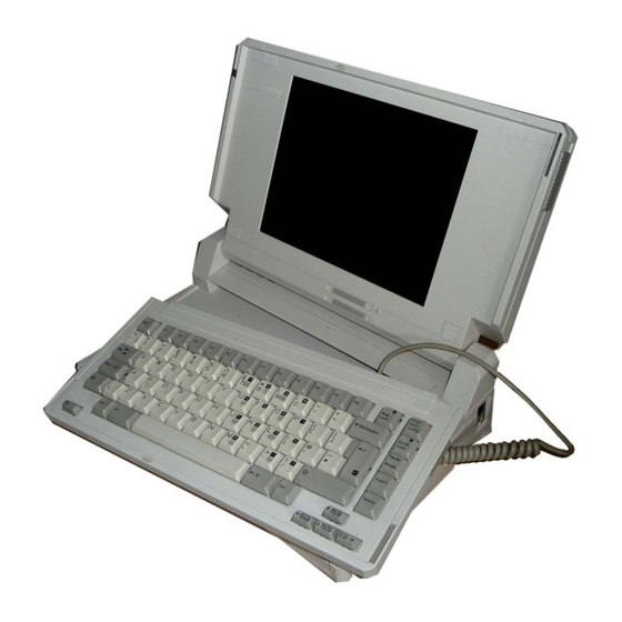
MAINTENANCE AND SERVICE GUIDE
COMPAQ SLT 386s/20 PERSONAL COMPUTER,
COMPAQ SLT/286 PERSONAL COMPUTER
First Edition (June 1990)
Text PN 118385-001
Preface
THE MAINTENANCE AND SERVICE GUIDE COMPAQ SLT 386s/20 PERSONAL COMPUTER,
COMPAQ SLT/286 PERSONAL COMPUTER is a troubleshooting guide.
as a reference when servicing the COMPAQ SLT 386s/20, Model 60 and Model 120,
or the COMPAQ SLT/286, Model 20 and Model 40.
reserves the right to make changes to the computers without notice.
diagrams and procedures in this document apply to these computers.
tests are designed to test only these products.
Interpreting Symbols
WARNING:
TEXT SET OFF IN THIS MANNER INDICATES THAT FAILURE TO FOLLOW
DIRECTIONS IN THE WARNING COULD RESULT IN BODILY HARM OR LOSS OF LIFE.
CAUTION:
TEXT SET OFF IN THIS MANNER INDICATES THAT FAILURE TO FOLLOW
DIRECTIONS COULD RESULT IN DAMAGE TO EQUIPMENT OR LOSS OF DATA.
IMPORTANT:
Text set off in this manner presents clarifying information or
specific instructions.
NOTE:
Text set off in this manner presents commentary sidelights, or
interesting points of information.
Locating Additional Information
Printed in the USA.
The software may be used or copied only in
No part of this guide
It can be used
Compaq Computer Corporation
The
Diagnostic
Advertisement
Table of Contents


Need help?
Do you have a question about the SLT 386s/20 and is the answer not in the manual?
Questions and answers