
Related Manuals for IEI Technology WAFER-KBN-1


Summary of Contents for IEI Technology WAFER-KBN-1
-
Page 1: User Manual
WAFER-KBN-i1 3.5" SBC MODEL: WAFER-KBN-i1 3.5” SBC with AMD Embedded G-Series SoC, Dual PCIe GbE, VGA, LVDS, iDP, SATA 6Gb/s, USB 3.0, iRIS-1010, PCIe Mini, HD Audio and RoHS User Manual Page i Rev. 1.02 – June 30, 2017... - Page 2 WAFER-KBN-i1 3.5" SBC Revision Date Version Changes 1.02 Modified Graphics Engine spec on page 8 June 30, 2017 1.01 Updated Section 1.5: Dimensions August 27, 2015 Updated Section 4.8: Chassis Installation 1.00 Initial release March 3, 2014 Page ii...
- Page 3 WAFER-KBN-i1 3.5" SBC Copyright COPYRIGHT NOTICE The information in this document is subject to change without prior notice in order to improve reliability, design and function and does not represent a commitment on the part of the manufacturer. In no event will the manufacturer be liable for direct, indirect, special, incidental, or consequential damages arising out of the use or inability to use the product or documentation, even if advised of the possibility of such damages.
- Page 4 WAFER-KBN-i1 3.5" SBC Manual Conventions WARNING Warnings appear where overlooked details may cause damage to the equipment or result in personal injury. Warnings should be taken seriously. CAUTION Cautionary messages should be heeded to help reduce the chance of losing data or damaging the product. NOTE These messages inform the reader of essential but non-critical information.
-
Page 5: Table Of Contents
WAFER-KBN-i1 3.5" SBC Table of Contents 1 INTRODUCTION......................1 1.1 I ......................2 NTRODUCTION 1.2 M ....................3 ODEL ARIATIONS 1.3 F ........................3 EATURES 1.4 C ......................4 ONNECTORS 1.5 D ....................... 5 IMENSIONS 1.6 D ........................ 7 1.7 T .................. - Page 6 WAFER-KBN-i1 3.5" SBC 3.2.10 iRIS Module Slot .................... 28 3.2.11 Keyboard and Mouse Connector..............28 3.2.12 LAN LED Connectors ..................29 3.2.13 LVDS Backlight Control Connector............... 30 3.2.14 LVDS Connector .................... 31 3.2.15 PCIe Mini Card Slot ..................33 3.2.16 Power and HDD LED Connector ..............34 3.2.17 Power Button Connector................
- Page 7 WAFER-KBN-i1 3.5" SBC 4.7.4 LVDS Voltage Selection..................61 4.8 C .................... 62 HASSIS NSTALLATION 4.8.1 Heat Sink Enclosure..................62 4.8.2 Motherboard Installation................. 63 4.9 I ............64 NTERNAL ERIPHERAL EVICE ONNECTIONS 4.9.1 AT/ATX Power Connection ................64 4.9.2 Audio Kit Installation..................65 4.9.3 LVDS LCD Installation ..................
- Page 8 WAFER-KBN-i1 3.5" SBC 5.4.2 Northbridge Configuration ................94 5.5 B ........................95 5.6 S ......................... 97 ECURITY 5.7 S & E ......................97 6 SOFTWARE DRIVERS ....................99 6.1 A ................100 VAILABLE OFTWARE RIVERS 6.2 S ................100 TARTING THE RIVER ROGRAM 6.3 G...
- Page 9 WAFER-KBN-i1 3.5" SBC List of Figures Figure 1-1: WAFER-KBN-i1......................2 Figure 1-2: Connectors ........................4 Figure 1-3: WAFER-KBN-i1 Dimensions (mm) ................6 Figure 1-4: Data Flow Diagram......................7 Figure 3-1: Peripheral Interface Connectors ................17 Figure 3-2: Power Connector Location ..................20 Figure 3-3: 5 V SATA Power Connector Locations ..............21 Figure 3-4: Audio Connector Location ..................22 Figure 3-5: Battery Connector Location..................23 Figure 3-6: Chassis Intrusion Connector Location..............24...
- Page 10 WAFER-KBN-i1 3.5" SBC Figure 3-27: System Fan Connector Location................44 Figure 3-28: USB 2.0 Connector Locations ................44 Figure 3-29: External Interface Connectors................45 Figure 3-30: Serial Port ........................47 Figure 3-31: VGA Connector .......................48 Figure 4-1: SO-DIMM Installation ....................52 Figure 4-2: Removing the Retention Screw for the iRIS-1010 Module........53 Figure 4-3: Inserting the iRIS-1010 Module into the Slot at an Angle ........53 Figure 4-4: Securing the iRIS-1010 Module ................54 Figure 4-5: Removing the Retention Screw ................55...
- Page 11 WAFER-KBN-i1 3.5" SBC Figure 6-7: Reboot Screen......................104 Figure 6-8: Intel® Network Connection Menu................. 105 Figure 6-9: LAN Driver Welcome Screen................. 105 Figure 6-10: LAN Driver License Agreement ................106 Figure 6-11: LAN Driver Setup Options................... 106 Figure 6-12: LAN Driver Installation ..................107 Figure 6-13: LAN Driver Installation Complete...............
- Page 12 WAFER-KBN-i1 3.5" SBC List of Tables Table 1-1: WAFER-KBN-i1 Model Variations ................3 Table 1-2: Technical Specifications....................10 Table 2-1: Packing List.........................14 Table 2-2: Optional Items......................15 Table 3-1: Peripheral Interface Connectors ................19 Table 3-2: Rear Panel Connectors ....................19 Table 3-3: Power Connector Pinouts..................20 Table 3-4: 5 V SATA Power Connector Pinouts ................21 Table 3-5: Audio Connector Pinouts ..................22 Table 3-6: Battery Connector Pinouts ..................23...
- Page 13 WAFER-KBN-i1 3.5" SBC Table 3-27: System Fan Connector Pinouts ................44 Table 3-28: USB 2.0 Connector Pinouts ..................45 Table 3-29: LAN Pinouts ......................45 Table 3-30: USB 3.0 Port Pinouts....................46 Table 3-31: Serial Port Pinouts....................47 Table 3-32: VGA Connector Pinouts...................47 Table 4-1: AT/ATX Power Mode Switch Settings...............59 Table 4-2: LVDS Panel Resolution Selection................60 Table 4-3: LVDS Voltage Selection Jumper Settings..............61 Table 5-1: BIOS Navigation Keys ....................73...
- Page 14 WAFER-KBN-i1 3.5" SBC BIOS Menus BIOS Menu 1: Main ........................74 BIOS Menu 2: Advanced ......................75 BIOS Menu 3: ACPI Settings .......................76 BIOS Menu 4: RTC Wake Settings ....................77 BIOS Menu 5: CPU Configuration ....................78 BIOS Menu 6: Node 0 Information ....................79 BIOS Menu 7: IDE Configuration....................79 BIOS Menu 8: USB Configuration ....................80 BIOS Menu 9: F81866 Super IO Configuration ................81...
-
Page 15: Introduction
WAFER-KBN-i1 3.5" SBC Chapter Introduction Page 1... -
Page 16: Introduction
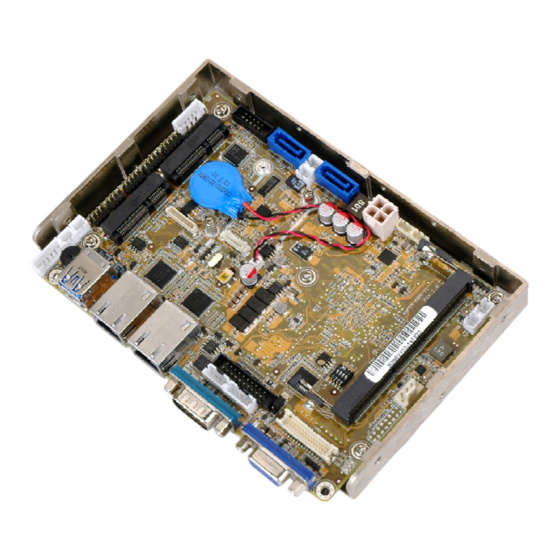
WAFER-KBN-i1 3.5" SBC 1.1 Introduction Figure 1-1: WAFER-KBN-i1 The WAFER-KBN-i1 3.5” SBC is an AMD Embedded G-Series SoC platform that supports one 1600 MHz or 1333 MHz DDR3 SO-DIMM memory. The WAFER-KBN-i1 provides two GbE interfaces through the Intel® I211 and the Intel® I210 GbE controllers. In addition, the WAFER-KBN-i1 includes VGA, LVDS and iDP interfaces for dual independent display. -
Page 17: Model Variations
WAFER-KBN-i1 3.5" SBC 1.2 Model Variations The model variations of the WAFER-KBN-i1 are listed below. Model No. WAFER-KBN-i1-4151-R10 AMD GX-415GA on-board SoC (1.5 GHz, quad-core, 2 MB cache, TDP=15W) AMD GX-210HA on-board SoC (1.0 GHz, dual-core, WAFER-KBN-i1-2101-R10 1 MB cache, TDP=9W) Table 1-1: WAFER-KBN-i1 Model Variations 1.3 Features Some of the WAFER-KBN-i1 motherboard features are listed below:... -
Page 18: Connectors
WAFER-KBN-i1 3.5" SBC 1.4 Connectors The connectors on the WAFER-KBN-i1 are shown in the figures below. Figure 1-2: Connectors Page 4... -
Page 19: Dimensions
WAFER-KBN-i1 3.5" SBC 1.5 Dimensions The main dimensions of the WAFER-KBN-i1 are shown in the diagram below. Page 5... -
Page 20: Figure 1-3: Wafer-Kbn-I1 Dimensions (Mm)
WAFER-KBN-i1 3.5" SBC Figure 1-3: WAFER-KBN-i1 Dimensions (mm) Page 6... -
Page 21: Data Flow
WAFER-KBN-i1 3.5" SBC 1.6 Data Flow Figure 1-4 shows the data flow between the system chipset, the CPU and other components installed on the motherboard. Figure 1-4: Data Flow Diagram Page 7... -
Page 22: Technical Specifications
WAFER-KBN-i1 3.5" SBC 1.7 Technical Specifications The WAFER-KBN-i1 technical specifications are listed in Table 1-2. Specification/Model WAFER-KBN-i1 3.5” Form Factor AMD GX-415GA on-board SoC (1.5GHz, quad-core, 2 MB cache, TDP=15W) AMD GX-210HA on-board SoC (1.0 GHz, dual-core, 1 MB cache, TDP=9W) AMD GX-420CA on-board SoC (2.0GHz, quad-core, 2 MB cache, TDP=25W) (by request) - Page 23 WAFER-KBN-i1 3.5" SBC Realtek ALC892 HD Audio codec One S/PDIF connector for digital audio (5-pin header) Audio One analog audio connector (10-pin box header) Super I/O Controller Fintek F81866 Watchdog Timer Software programmable, supports 1~255 sec. system reset One full-size/half-size PCIe Mini card slot with mSATA support Expansion (co-lay SATA port 2) IPMI 2.0...
-
Page 24: Table 1-2: Technical Specifications
WAFER-KBN-i1 3.5" SBC +12V@2.12A (AMD GX-415GA SoC with one 4 GB 1333 MHz Power Consumption DDR3 SO-DIMM) Operating Temperature 0ºC ~ 60ºC Storage Temperature -10ºC ~ 85ºC Operating Humidity 5% ~ 95% (non-condensing) Dimensions 146 mm x 102 mm Weight (GW/NW) 600 g/250 g Table 1-2: Technical Specifications Page 10... -
Page 25: Packing List
WAFER-KBN-i1 3.5" SBC Chapter Packing List Page 11... -
Page 26: Anti-Static Precautions
WAFER-KBN-i1 3.5" SBC 2.1 Anti-static Precautions WARNING! Static electricity can destroy certain electronics. Make sure to follow the ESD precautions to prevent damage to the product, and injury to the user. Make sure to adhere to the following guidelines: Wear an anti-static wristband: Wearing an anti-static wristband can prevent electrostatic discharge. -
Page 27: Packing List
WAFER-KBN-i1 3.5" SBC 2.3 Packing List NOTE: If any of the components listed in the checklist below are missing, do not proceed with the installation. Contact the IEI reseller or vendor the WAFER-KBN-i1 was purchased from or contact an IEI sales representative directly by sending an email to sales@ieiworld.com. -
Page 28: Optional Items
WAFER-KBN-i1 3.5" SBC Quantity Item and Part Number Image One Key Recovery CD Quick installation guide Table 2-1: Packing List 2.4 Optional Items These optional items are available. Item and Part Number Image iRIS-1010 module, IPMI 2.0 adapter card with AST1010 BMC chip for PCIe Mini socket interface (P/N: iRIS-1010-R10) Dual-port USB 2.0 cable... -
Page 29: Table 2-2: Optional Items
WAFER-KBN-i1 3.5" SBC Item and Part Number Image DisplayPort to HDMI converter board for IEI iDP connector (P/N: DP-HDMI-R10) DisplayPort to VGA converter board for IEI iDP connector (P/N: DP-VGA-R10) DisplayPort to DVI-D converter board for IEI iDP connector (P/N: DP-DVI-R10) DisplayPort to DisplayPort converter board for IEI iDP connector (P/N: DP-DP-R10) -
Page 30: Connectors
WAFER-KBN-i1 3.5" SBC Chapter Connectors Page 16... -
Page 31: Peripheral Interface Connectors
WAFER-KBN-i1 3.5" SBC 3.1 Peripheral Interface Connectors This chapter details all the peripheral interface connectors. 3.1.1 Layout The figures below show all the peripheral interface connectors. Figure 3-1: Peripheral Interface Connectors Page 17... -
Page 32: Peripheral Interface Connectors
WAFER-KBN-i1 3.5" SBC 3.1.2 Peripheral Interface Connectors The table below shows a list of the peripheral interface connectors on the WAFER-KBN-i1. Detailed descriptions of these connectors can be found below. Connector Type Label 4-pin Molex power +12V power connector connector SATA_PWR1, 5 V SATA power connectors 2-pin wafer... -
Page 33: External Interface Panel Connectors
WAFER-KBN-i1 3.5" SBC Connector Type Label Serial port, RS-422/485 4-pin wafer COM4 SMBus connector 4-pin wafer 204-pin DDR3 SO-DIMM connector DIMM1 SO-DIMM connector S/PDIF connector 5-pin header SPDIF1 SPI flash connector 6-pin wafer SPI1 System fan connector 4-pin wafer FAN1 USB 2.0 connectors 8-pin header USB2, USB3... -
Page 34: Power Connector
WAFER-KBN-i1 3.5" SBC 3.2.1 +12V Power Connector CN Label: 4-pin Molex power connector CN Type: CN Location: See Figure 3-2 CN Pinouts: See Table 3-3 The power connector is connected to an external power supply and supports +12V power input. Power is provided to the system, from the power supply through this connector. Figure 3-2: Power Connector Location Description Description... -
Page 35: Audio Connector
WAFER-KBN-i1 3.5" SBC Use the 5 V SATA power connectors to connect to SATA device power connections. Figure 3-3: 5 V SATA Power Connector Locations Description Table 3-4: 5 V SATA Power Connector Pinouts 3.2.3 Audio Connector CN Label: AUDIO1 CN Type: 10-pin box header See Figure 3-4... -
Page 36: Battery Connector
WAFER-KBN-i1 3.5" SBC Figure 3-4: Audio Connector Location Description Description SPK_R LINE1_R AUD_GND AUD_GND SPK_L LINE1_L AUD_GND AUD_GND MIC1_R MIC1_L Table 3-5: Audio Connector Pinouts 3.2.4 Battery Connector CAUTION: Risk of explosion if battery is replaced by an incorrect type. Only certified engineers should replace the on-board battery. -
Page 37: Chassis Intrusion Connector
WAFER-KBN-i1 3.5" SBC This is connected to the system battery. The battery provides power to the system clock to retain the time when power is turned off. Figure 3-5: Battery Connector Location Description VBATT Table 3-6: Battery Connector Pinouts 3.2.5 Chassis Intrusion Connector CN Label: CN10 2-pin wafer... -
Page 38: Digital I/O Connector
WAFER-KBN-i1 3.5" SBC Figure 3-6: Chassis Intrusion Connector Location Description Pull high to +3.3V_ALW CHASSIS OPEN# Table 3-7: Chassis Intrusion Connector Pinouts 3.2.6 Digital I/O Connector CN Label: DIO1 CN Type: 10-pin header CN Location: See Figure 3-7 See Table 3-8 CN Pinouts: The digital I/O connector provides programmable input and output for external devices. -
Page 39: I 2 C Connector
WAFER-KBN-i1 3.5" SBC Description Description Output 3 Output 2 Output 1 Output 0 Input 3 Input 2 Input 1 Input 0 Table 3-8: Digital I/O Connector Pinouts 3.2.7 I C Connector CN Label: CN Type: 4-pin wafer CN Location: See Figure 3-8 CN Pinouts: See Table 3-9 The I... -
Page 40: Internal Displayport Connector
WAFER-KBN-i1 3.5" SBC Description C DATA C CLK Table 3-9: I C Connector Pinouts 3.2.8 Internal DisplayPort Connector CN Label: 20-pin box header CN Type: CN Location: See Figure 3-9 CN Pinouts: See Table 3-10 The DisplayPort connector supports HDMI, LVDS, VGA, DVI and DisplayPort graphics interfaces with up to 2560x1600 resolution. -
Page 41: Ipmi Led Connector
WAFER-KBN-i1 3.5" SBC Description Description Lane3- Lane0+ Lane1+ Lane0- Lane1- VCC3 VCC5 Table 3-10: Internal DisplayPort Connector Pinouts 3.2.9 IPMI LED Connector CN Label: CN Type: 2-pin wafer CN Location: See Figure 3-10 CN Pinouts: See Table 3-11 The IPMI LED connector is used to connect to the IPMI LED indicator on the chassis. Figure 3-10: IPMI LED Connector Location Description ID_LED+... -
Page 42: Iris Module Slot
WAFER-KBN-i1 3.5" SBC 3.2.10 iRIS Module Slot CN Label: IPMI1 iRIS module slot CN Type: CN Location: See Figure 3-11 The iRIS module slot allows installation of the iRIS-1010 module. Figure 3-11: iRIS Module Slot Location WARNING: The iRIS module slot is designed to install the iRIS-1010 module only. DO NOT install other modules into the iRIS module slot. -
Page 43: Lan Led Connectors
WAFER-KBN-i1 3.5" SBC CN Location: See Figure 3-12 CN Pinouts: See Table 3-12 The keyboard and mouse connector connects to a PS/2 Y-cable that can be connected to a PS/2 keyboard and mouse. Figure 3-12: Keyboard and Mouse Connector Location Description Mouse Data Mouse Clock... -
Page 44: Lvds Backlight Control Connector
WAFER-KBN-i1 3.5" SBC Figure 3-13: LAN LED Connector Locations Description +V3.3LAN LED LINK_ACT- Table 3-13: LAN LED Connector Pinouts 3.2.13 LVDS Backlight Control Connector CN Label: INV1 CN Type: 5-pin wafer CN Location: See Figure 3-14 CN Pinouts: See Table 3-14 The backlight control connector provides the backlight on the LCD display connected to the WAFER-KBN-i1 with +12V of power. -
Page 45: Lvds Connector
WAFER-KBN-i1 3.5" SBC Figure 3-14: LVDS Backlight Control Connector Location Description LCD_BKLTCTL GROUND +12V GROUND BACKLIGHT ENABLE Table 3-14: LVDS Backlight Control Connector Pinouts 3.2.14 LVDS Connector NOTE: Before using the LVDS connector, the user has to enable the LVDS Output BIOS option. -
Page 46: Figure 3-15: Lvds Connector Location
WAFER-KBN-i1 3.5" SBC The 30-pin LVDS LCD connector can be connected to an 18/24-bit dual-channel LVDS panel. Figure 3-15: LVDS Connector Location Description Description A_Y0 A_Y0# A_Y1 A_Y1# A_Y2 A_Y2# A_CK A_CK# A_Y3 A_Y3# B_Y0 B_Y0# B_Y1 B_Y1# B_Y2 B_Y2# B_CK B_CK# B_Y3... -
Page 47: Pcie Mini Card Slot
WAFER-KBN-i1 3.5" SBC 3.2.15 PCIe Mini Card Slot CN Label: M_PCIE2 PCIe Mini card slot CN Type: CN Location: See Figure 3-16 CN Pinouts: See Table 3-16 The PCIe Mini card slot enables a full-size/half-size PCIe Mini card expansion module to be connected to the board. -
Page 48: Power And Hdd Led Connector
WAFER-KBN-i1 3.5" SBC Description Description PCIRST# PCIE_RXN (SATA_RX+) VCC3 PCIE_RXP (SATA_RX-) 1.5V SMBCLK PCIE_TXN (SATA_TX-) SMBDATA PCIE_TXP (SATA_TX+) USBD- USBD+ VCC3 VCC3 1.5V VCC3 Table 3-16: PCIe Mini Card Slot Pinouts 3.2.16 Power and HDD LED Connector CN Label: CN Type: 6-pin wafer CN Location: See Figure 3-17... -
Page 49: Power Button Connector
WAFER-KBN-i1 3.5" SBC Figure 3-17: Power and HDD LED Connector Location Function Description Power LED+ Power LED Power LED- HDD LED+ HDD LED HDD LED- Table 3-17: Power and HDD LED Connector Pinouts 3.2.17 Power Button Connector CN Label: PWR_BTN1 CN Type: 2-pin wafer See Figure 3-18... -
Page 50: Reset Button Connector
WAFER-KBN-i1 3.5" SBC Figure 3-18: Power Button Connector Location Description PWR_BTN+ PWR_BTN- Table 3-18: Power Button Connector Pinouts 3.2.18 Reset Button Connector CN Label: RST_BTN1 CN Type: 2-pin wafer CN Location: See Figure 3-19 See Table 3-19 CN Pinouts: The reset button connector is connected to a reset switch on the system chassis to enable users to reboot the system when the system is turned on. -
Page 51: Sata 6Gb/S Connectors
WAFER-KBN-i1 3.5" SBC Description RESET+ RESET- Table 3-19: Reset Button Connector Pinouts 3.2.19 SATA 6Gb/s Connectors CN Label: SATA1, SATA2 CN Type: 7-pin SATA drive connector See Figure 3-20 CN Location: CN Pinouts: See Table 3-20 The SATA drive connectors can be connected to SATA drives and support up to 6Gb/s data transfer rate. -
Page 52: Serial Port Connector, Rs-232
WAFER-KBN-i1 3.5" SBC Description Table 3-20: SATA 6Gb/s Drive Connector Pinouts 3.2.20 Serial Port Connector, RS-232 CN Label: COM2, COM3 CN Type: 10-pin header CN Location: See Figure 3-21 CN Pinouts: See Table 3-21 The 10-pin serial port connector provides one RS-232 serial communications channel. The COM serial port connector can be connected to an external RS-232 serial port device. -
Page 53: Serial Port Connector, Rs-422/485
WAFER-KBN-i1 3.5" SBC 3.2.21 Serial Port Connector, RS-422/485 CN Label: COM4 4-pin wafer CN Type: CN Location: See Figure 3-22 CN Pinouts: See Table 3-22 This connector provides RS-422 or RS-485 communications. Figure 3-22: RS-422/485 Serial Port Connector Location Description RXD422- RXD422+ TXD422+/TXD485+... -
Page 54: Smbus Connector
WAFER-KBN-i1 3.5" SBC RS-422 Pinouts RS-485 Pinouts Table 3-23: DB-9 RS-422/485 Pinouts 3.2.22 SMBus Connector CN Label: CN Type: 4-pin wafer See Figure 3-23 CN Location: CN Pinouts: See Table 3-24 The SMBus (System Management Bus) connector provides low-speed system management communications. -
Page 55: So-Dimm Connector
WAFER-KBN-i1 3.5" SBC Description SMBUS CLK Table 3-24: SMBus Connector Pinouts 3.2.23 SO-DIMM Connector CN Label: DIMM1 CN Type: 204-pin DDR3 SO-DIMM connector CN Location: See Figure 3-24 The SO-DIMM connector is for installing the SO-DIMM on the system. Figure 3-24: SO-DIMM Connector Location 3.2.24 S/PDIF Connector CN Label: SPDIF1... -
Page 56: Spi Flash Connector
WAFER-KBN-i1 3.5" SBC Figure 3-25: S/PDIF Connector Location Description SPDIF_OUT SPDIF_IN Table 3-25: S/PDIF Connector Pinouts 3.2.25 SPI Flash Connector CN Label: SPI1 6-pin wafer CN Type: CN Location: See Figure 3-26 CN Pinouts: See Table 3-26 The SPI flash connector is used to flash the SPI ROM. Page 42... -
Page 57: System Fan Connector
WAFER-KBN-i1 3.5" SBC Figure 3-26: SPI Flash Connector Location Description SPI_POWER SPI_2N_CS# SPI_2N_MISO SPI_2N_CLK SPI_2N_MOSI Table 3-26: SPI Flash Connector Pinouts 3.2.26 System Fan Connector CN Label: FAN1 4-pin wafer CN Type: CN Location: See Figure 3-27 CN Pinouts: See Table 3-27 The fan connector attaches to a system cooling fan. -
Page 58: Usb 2.0 Connectors
WAFER-KBN-i1 3.5" SBC Figure 3-27: System Fan Connector Location Description +V12S Rotation Signal PWM Control Signal Table 3-27: System Fan Connector Pinouts 3.2.27 USB 2.0 Connectors CN Label: USB2, USB3 8-pin header CN Type: CN Location: See Figure 3-28 CN Pinouts: See Table 3-28 Each USB header can connect to two USB 2.0 devices. -
Page 59: External Interface Connectors
WAFER-KBN-i1 3.5" SBC Description Description USB_VCC DATA- DATA+ DATA+ DATA- USB_VCC Table 3-28: USB 2.0 Connector Pinouts 3.3 External Interface Connectors The figure below shows the external peripheral interface connector (EPIC) panel. The EPIC panel consists of the following: Figure 3-29: External Interface Connectors 3.3.1 Ethernet Connectors CN Label: LAN1, LAN2... -
Page 60: Usb 3.0 Ports
WAFER-KBN-i1 3.5" SBC 3.3.2 USB 3.0 Ports CN Label: USB1 Dual USB 3.0 port CN Type: CN Location: See Figure 3-29 CN Pinouts: See Table 3-30 The WAFER-KBN-i1 has two external USB 3.0 ports. Description Description USB_VCC USB2_D0- USB2_D0- USB3_RXD0- USB3_RXD0+ USB3_TXD0- USB3_TXD0+... -
Page 61: Vga Connector
WAFER-KBN-i1 3.5" SBC Description Description DATA TERMINAL READY (DTR) RING INDICATOR (RI) Table 3-31: Serial Port Pinouts Figure 3-30: Serial Port 3.3.4 VGA Connector CN Label: VGA1 CN Type: 15-pin female CN Location: See Figure 3-29 CN Pinouts: See Figure 3-31 and Table 3-32 The VGA connector connects to a monitor that accepts a standard VGA input. -
Page 62: Figure 3-31: Vga Connector
WAFER-KBN-i1 3.5" SBC Figure 3-31: VGA Connector Page 48... -
Page 63: Installation
WAFER-KBN-i1 3.5" SBC Chapter Installation Page 49... -
Page 64: Anti-Static Precautions
WAFER-KBN-i1 3.5" SBC 4.1 Anti-static Precautions WARNING: Failure to take ESD precautions during installation may result in permanent damage to the product and severe injury to the user. Electrostatic discharge (ESD) can cause serious damage to electronic components, including the WAFER-KBN-i1. Dry climates are especially susceptible to ESD. It is therefore critical to strictly adhere to the following anti-static precautions whenever the WAFER-KBN-i1, or any other electrical component, is handled. -
Page 65: So-Dimm Installation
WAFER-KBN-i1 3.5" SBC WARNING: The installation instructions described in this manual should be carefully followed in order to prevent damage to the WAFER-KBN-i1, WAFER-KBN-i1 components and injury to the user. Before and during the installation please DO the following: Read the user manual: The user manual provides a complete description of the installation instructions and configuration options. -
Page 66: Iris-1010 Module Installation
WAFER-KBN-i1 3.5" SBC Figure 4-1: SO-DIMM Installation Step 1: Locate the SO-DIMM socket. Place the board on an anti-static mat. Step 2: Align the SO-DIMM with the socket. Align the notch on the memory with the notch on the memory socket. Step 3: Insert the SO-DIMM. -
Page 67: Figure 4-2: Removing The Retention Screw For The Iris-1010 Module
WAFER-KBN-i1 3.5" SBC Figure 4-2: Removing the Retention Screw for the iRIS-1010 Module Step 3: Insert into the slot at an angle. Line up the notch on the module with the notch on the slot. Slide the iRIS-1010 module into the slot at an angle of about 20º (Figure 4-3). -
Page 68: Full-Size Pcie Mini Card Installation
WAFER-KBN-i1 3.5" SBC Step 4: Secure the iRIS-1010 module. Secure the iRIS-1010 module with the retention screw previously removed (Figure 4-4). Figure 4-4: Securing the iRIS-1010 Module NOTE: After installing the iRIS-1010 module, use LAN1 port to establish a network connection. 4.5 Full-size PCIe Mini Card Installation The PCIe Mini card slot allows installation of either a full-size or half-size PCIe Mini card. -
Page 69: Figure 4-5: Removing The Retention Screw
WAFER-KBN-i1 3.5" SBC Figure 4-5: Removing the Retention Screw Step 3: Insert into the socket at an angle. Line up the notch on the card with the notch on the slot. Slide the PCIe Mini card into the socket at an angle of about 20º (Figure 4-6). -
Page 70: Half-Size Pcie Mini Card Installation
WAFER-KBN-i1 3.5" SBC Step 4: Secure the full-size PCIe Mini card. Secure the full-size PCIe Mini card with the retention screw previously removed (Figure 4-7). Figure 4-7: Securing the Full-size PCIe Mini Card 4.6 Half-size PCIe Mini Card Installation The PCIe Mini card slot allows installation of either a full-size or half-size PCIe Mini card. To install a half-size PCIe Mini card, please follow the steps below. -
Page 71: Figure 4-8: Removing The Standoff
WAFER-KBN-i1 3.5" SBC Figure 4-8: Removing the Standoff Step 4: Install the standoff to the screw hole for the half-size PCIe Mini card. Install the previously removed standoff to the screw hole for the half-size PCIe Mini card (Figure 4-9). Figure 4-9: Installing the Standoff Page 57... -
Page 72: Figure 4-10: Inserting The Half-Size Pcie Mini Card Into The Slot At An Angle
WAFER-KBN-i1 3.5" SBC Step 5: Insert into the socket at an angle. Line up the notch on the card with the notch on the slot. Slide the PCIe Mini card into the slot at an angle of about 20º (Figure 4-10). Figure 4-10: Inserting the Half-size PCIe Mini Card into the Slot at an Angle Step 6: Secure the half-size PCIe Mini card. -
Page 73: System Configuration
WAFER-KBN-i1 3.5" SBC 4.7 System Configuration The system configuration is controlled by buttons, jumpers and switches. The system configuration should be performed before installation. 4.7.1 AT/ATX Power Mode Selection The AT and ATX power mode selection is made through the AT/ATX power mode switch which is shown in Figure 4-12. -
Page 74: Lvds Panel Resolution Selection
WAFER-KBN-i1 3.5" SBC 4.7.3 LVDS Panel Resolution Selection Jumper Label: Jumper Type: DIP switch Jumper Settings: See Table 4-2 See Figure 4-14 Jumper Location: Selects the resolution of the LCD panel connected to the LVDS connector. * ON=0, OFF=1; Single=S, Dual=D SW1 (4-3-2-1) Description 0000... -
Page 75: Lvds Voltage Selection
WAFER-KBN-i1 3.5" SBC 4.7.4 LVDS Voltage Selection WARNING: Permanent damage to the screen and WAFER-KBN-i1 may occur if the wrong voltage is selected with this jumper. Please refer to the user guide that came with the monitor to select the correct voltage. Jumper Label: 3-pin header Jumper Type:... -
Page 76: Chassis Installation
WAFER-KBN-i1 3.5" SBC 4.8 Chassis Installation 4.8.1 Heat Sink Enclosure WARNING: Never run the WAFER-KBN-i1 without the heat sink secured to the board. The heat sink ensures the system remains cool and does not need addition heat sinks to cool the system. WARNING: When running the WAFER-KBN-i1, do not put the WAFER-KBN-i1 directly on a surface that can not dissipate system heat, especially the... -
Page 77: Motherboard Installation
WAFER-KBN-i1 3.5" SBC 4.8.2 Motherboard Installation Each side of the heat sink enclosure has several screw holes allowing the WAFER-KBN-i1 to be mounted into a chassis (please refer to Figure 1-3 for the detailed dimensions). The user can design or select a chassis that has screw holes matching up with the holes on the heat sink enclosure for installing the WAFER-KBN-i1. -
Page 78: Internal Peripheral Device Connections
WAFER-KBN-i1 3.5" SBC 4.9 Internal Peripheral Device Connections This section outlines the installation of peripheral devices to the on-board connectors. 4.9.1 AT/ATX Power Connection Follow the instructions below to connect the WAFER-KBN-i1 to an AT or ATX power supply. WARNING: Disconnect the power supply power cord from its AC power source to prevent a sudden power surge to the WAFER-KBN-i1. -
Page 79: Audio Kit Installation
WAFER-KBN-i1 3.5" SBC Step 3: Connect Power Cable to Power Supply. Connect one of the 4-pin (1x4) Molex type power cable connectors to an AT/ATX power supply. See Figure 4-19. Figure 4-19: Connect Power Cable to Power Supply 4.9.2 Audio Kit Installation The Audio Kit that came with the WAFER-KBN-i1 connects to the 10-pin audio connector on the WAFER-KBN-i1. -
Page 80: Lvds Lcd Installation
WAFER-KBN-i1 3.5" SBC Figure 4-20: Audio Kit Cable Connection Step 3: Connect the audio devices. Connect speakers to the line-out audio jack. Connect the output of an audio device to the line-in audio jack. Connect a microphone to the mic-in audio jack. 4.9.3 LVDS LCD Installation The WAFER-KBN-i1 can be connected to a TFT LCD screen through the LVDS crimp connectors on the board. -
Page 81: Figure 4-21: Lvds Connector
WAFER-KBN-i1 3.5" SBC WARNING: The diagram below is merely for illustration. The configuration and connection of the cables from the TFT LCD screen being installed may be different. Please refer to the installation manual that came with the TFT LCD screen. Figure 4-21: LVDS Connector Step 3: Locate the backlight inverter connector. -
Page 82: Cable Installation
WAFER-KBN-i1 3.5" SBC Figure 4-22: Backlight Inverter Connection 4.9.4 RS-232 Cable Installation The RS-232 cable consists of one serial port connector attached to a serial communications cable that is then attached to a DB-9 male connector that is mounted onto a bracket. To install the RS-232 cable, please follow the steps below. Step 1: Locate the connectors. -
Page 83: Sata Drive Connection
WAFER-KBN-i1 3.5" SBC Figure 4-23: RS-232 Cable Installation Step 4: Secure the bracket. The RS-232 connector has one DB-9 male connector secured to a bracket. To secure the bracket to the chassis, please refer to the reference material that came with the chassis.Step 0: 4.9.5 SATA Drive Connection The WAFER-KBN-i1 is shipped with two SATA signal and power cables. -
Page 84: Figure 4-24: Sata Drive Cable Connection
WAFER-KBN-i1 3.5" SBC Figure 4-24: SATA Drive Cable Connection Step 3: Connect the cable to the SATA disk. Connect the connector on the other end of the cable to the connector at the back of the SATA drive. See Figure 4-24. Step 4: To remove the SATA cable from the SATA connector, press the clip on the connector at the end of the cable. -
Page 85: Bios
WAFER-KBN-i1 3.5" SBC Chapter BIOS Page 71... -
Page 86: Introduction
WAFER-KBN-i1 3.5" SBC 5.1 Introduction The BIOS is programmed onto the BIOS chip. The BIOS setup program allows changes to certain system settings. This chapter outlines the options that can be changed. NOTE: Some of the BIOS options may vary throughout the life cycle of the product and are subject to change without prior notice. -
Page 87: Getting Help
WAFER-KBN-i1 3.5" SBC Function Page Up key Move to the next page Page Dn key Move to the previous page Esc key Main Menu – Quit and not save changes into CMOS Status Page Setup Menu and Option Page Setup Menu -- Exit current page and return to Main Menu General help, only for Status Page Setup Menu and Option Page Setup Menu... -
Page 88: Main
WAFER-KBN-i1 3.5" SBC The following sections completely describe the configuration options found in the menu items at the top of the BIOS screen and listed above. 5.2 Main The Main BIOS menu (BIOS Menu 1) appears when the BIOS Setup program is entered. The Main menu gives an overview of the basic system information. -
Page 89: Advanced
WAFER-KBN-i1 3.5" SBC 5.3 Advanced Use the Advanced menu (BIOS Menu 2) to configure the CPU and peripheral devices through the following sub-menus: WARNING: Setting the wrong values in the sections below may cause the system to malfunction. Make sure that the settings made are compatible with the hardware. -
Page 90: Acpi Settings
WAFER-KBN-i1 3.5" SBC 5.3.1 ACPI Settings The ACPI Settings menu (BIOS Menu 3) configures the Advanced Configuration and Power Interface (ACPI) options. Aptio Setup Utility – Copyright (C) 2012 American Megatrends, Inc. Advanced ACPI Settings Select ACPI sleep state the system will enter ACPI Sleep State [S3 only(Suspend to…] when the SUSPEND button... -
Page 91: Bios Menu 4: Rtc Wake Settings
WAFER-KBN-i1 3.5" SBC Aptio Setup Utility – Copyright (C) 2012 American Megatrends, Inc. Advanced Wake system with Fixed Time [Disabled] Enable or disable System wake on alarm event. When enabled, System will wake on the date::hr::min::sec specified ---------------------- : Select Screen ↑... -
Page 92: Cpu Configuration
WAFER-KBN-i1 3.5" SBC 5.3.3 CPU Configuration Use the CPU Configuration menu (BIOS Menu 5) to view detailed CPU specifications. Aptio Setup Utility – Copyright (C) 2012 American Megatrends, Inc. Advanced CPU Configuration Enabled/disable CPU Virtualization SVM Mode [Enabled] Core Leveling Mode [Automatic mode] ---------------------- >... -
Page 93: Node 0 Information
WAFER-KBN-i1 3.5" SBC 5.3.3.1 Node 0 Information The Node 0 Information submenu (BIOS Menu 6) lists detailed CPU specifications. Aptio Setup Utility – Copyright (C) 2012 American Megatrends, Inc. Advanced Socekt0: AMD GX-210HA SOC with Radeon(tm) HD Graphics Dual Core Running @ 1009 MHz 900 mV Max Speed:1000 MHz Intended Speed:1000 MHz Min Speed:800 MHz... -
Page 94: Usb Configuration
WAFER-KBN-i1 3.5" SBC 5.3.5 USB Configuration Use the USB Configuration menu (BIOS Menu 8) to read USB configuration information and configure the USB settings. Aptio Setup Utility – Copyright (C) 2012 American Megatrends, Inc. Advanced USB Configuration Enables Legacy USB support. -
Page 95: F81866 Super Io Configuration
WAFER-KBN-i1 3.5" SBC Enabled Legacy USB support enabled EFAULT Legacy USB support disabled Disabled Auto Legacy USB support disabled if no USB devices are connected 5.3.6 F81866 Super IO Configuration Use the F81866 Super IO Configuration menu (BIOS Menu 9) to set or change the configurations for the serial ports. -
Page 96: Serial Port N Configuration
WAFER-KBN-i1 3.5" SBC 5.3.6.1 Serial Port n Configuration Use the Serial Port n Configuration menu (BIOS Menu 10) to configure the serial port n. Aptio Setup Utility – Copyright (C) 2012 American Megatrends, Inc. Advanced Serial Port n Configuration Enable or Disable Serial Port (COM) Serial Port [Enabled]... - Page 97 WAFER-KBN-i1 3.5" SBC IO=2F8h; Serial Port I/O port address is 2F8h and the interrupt IRQ=3, 4 address is IRQ3, 4 Serial Port I/O port address is 3E8h and the interrupt IO=3E8h; address is IRQ3, 4 IRQ=3, 4 IO=2E8h; Serial Port I/O port address is 2E8h and the interrupt IRQ=3, 4 address is IRQ3, 4 5.3.6.1.2 Serial Port 2 Configuration...
- Page 98 WAFER-KBN-i1 3.5" SBC 5.3.6.1.3 Serial Port 3 Configuration Serial Port [Enabled] Use the Serial Port option to enable or disable the serial port. Disabled Disable the serial port Enable the serial port Enabled EFAULT Change Settings [Auto] Use the Change Settings option to change the serial port IO port address and interrupt address.
- Page 99 WAFER-KBN-i1 3.5" SBC 5.3.6.1.4 Serial Port 4 Configuration Serial Port [Enabled] Use the Serial Port option to enable or disable the serial port. Disabled Disable the serial port Enable the serial port Enabled EFAULT Change Settings [Auto] Use the Change Settings option to change the serial port IO port address and interrupt address.
-
Page 100: F81866 H/W Monitor
WAFER-KBN-i1 3.5" SBC 5.3.7 F81866 H/W Monitor The F81866 H/W Monitor menu (BIOS Menu 11) contains the fan configuration submenu and displays the system temperatures and voltages. Aptio Setup Utility – Copyright (C) 2012 American Megatrends, Inc. Advanced PC Health Status Smart Fan Mode Select >... -
Page 101: Bios Menu 12: Smar Fan Mode Configuration
WAFER-KBN-i1 3.5" SBC Aptio Setup Utility – Copyright (C) 2012 American Megatrends, Inc. Advanced Smart Fan Mode Configuration Smart Fan Mode Select FAN1 Smart Fan Control [Auto Duty-Cycle Mode] CPU Temperature 1 CPU Temperature 2 --------------------- CPU Temperature 3 CPU Temperature 4 : Select Screen ↑... -
Page 102: Serial Port Console Redirection
WAFER-KBN-i1 3.5" SBC 5.3.8 Serial Port Console Redirection The Serial Port Console Redirection menu (BIOS Menu 13) allows the console redirection options to be configured. Console redirection allows users to maintain a system remotely by re-directing keyboard input and text output through the serial port. Aptio Setup Utility –... - Page 103 WAFER-KBN-i1 3.5" SBC Terminal Type [ANSI] Use the Terminal Type option to specify the remote terminal type. The target terminal type is VT100 VT100 VT100+ The target terminal type is VT100+ VT-UTF8 The target terminal type is VT-UTF8 ANSI The target terminal type is ANSI EFAULT Bits per second [115200] Use the Bits per second option to specify the serial port transmission speed.
-
Page 104: Chipset
WAFER-KBN-i1 3.5" SBC The parity bit is 0 if the number of ones in the data bits is odd. The parity bit is always 1. This option does not Mark provide error detection. Space The parity bit is always 0. This option does not provide error detection. -
Page 105: Southbridge Configuration
WAFER-KBN-i1 3.5" SBC 5.4.1 Southbridge Configuration Use the South Bridge menu (BIOS Menu 15) to configure the Southbridge parameters. Aptio Setup Utility – Copyright (C) 2012 American Megatrends, Inc. Chipset Select AC power state Auto Power Button Status [Disabled(ATX)] when power is re-applied Restore AC Power Loss [Last State] after a power failure. -
Page 106: Sb Sata Configuration
WAFER-KBN-i1 3.5" SBC Wireless LAN Device [Enabled] Use the Wireless LAN Device BIOS option to enable or disable the wireless LAN device. Disabled Wireless LAN device is disabled. Enabled Wireless LAN device is enabled. EFAULT LVDS Output [Disabled] Use the LVDS Output BIOS option to enable or disable the LVDS output function. LVDS output function is disabled. -
Page 107: Sb Hd Azalia Configuration
WAFER-KBN-i1 3.5" SBC OnChip SATA Channel [Enabled] Use the OnChip SATA Channel option to configure the on-chip serial ATA channel. Enables the on-chip serial ATA channel. Enabled EFAULT Disabled Disables the on-chip serial ATA channel. OnChip SATA Type [Native IDE] Use the OnChip SATA Type option to configure SATA devices as normal IDE devices. -
Page 108: Northbridge Configuration
WAFER-KBN-i1 3.5" SBC Auto The onboard High Definition Audio controller automatically detected and enabled The onboard High Definition Audio controller is disabled Disabled Enabled The onboard High Definition Audio controller is enabled EFAULT 5.4.2 Northbridge Configuration Use the North Bridge menu (BIOS Menu 18) to display the memory information. Aptio Setup Utility –... -
Page 109: Boot
WAFER-KBN-i1 3.5" SBC 5.5 Boot Use the Boot menu (BIOS Menu 19) to configure system boot options. Aptio Setup Utility – Copyright (C) 2012 American Megatrends, Inc. Main Advanced Chipset Boot Security Save & Exit Boot Configuration Select the keyboard Bootup NumLock State [On] NumLock state... - Page 110 WAFER-KBN-i1 3.5" SBC Quiet Boot [Enabled] Use the Quiet Boot BIOS option to select the screen display when the system boots. Normal POST messages displayed Disabled Enabled OEM Logo displayed instead of POST messages EFAULT Launch PXE OpROM [Disabled] Use the Launch PXE OpROM option to enable or disable boot option for legacy network devices.
-
Page 111: Security
WAFER-KBN-i1 3.5" SBC 5.6 Security Use the Security menu (BIOS Menu 20) to set system and user passwords. Aptio Setup Utility – Copyright (C) 2012 American Megatrends, Inc. Main Advanced Chipset Boot Security Save & Exit Password Description Set Administrator Password If ONLY the Administrator’s password is set, then this only limits access to Setup and is... -
Page 112: Bios Menu 21: Save & Exit
WAFER-KBN-i1 3.5" SBC Aptio Setup Utility – Copyright (C) 2012 American Megatrends, Inc. Main Advanced Chipset Boot Security Save & Exit Save Changes and Reset Reset the system after Discard Changes and Reset saving the changes. Restore Defaults Save as User Defaults Restore User Defaults --------------------- : Select Screen... -
Page 113: Software Drivers
WAFER-KBN-i1 3.5" SBC Chapter Software Drivers Page 99... -
Page 114: Available Software Drivers
WAFER-KBN-i1 3.5" SBC 6.1 Available Software Drivers NOTE: The content of the CD may vary throughout the life cycle of the product and is subject to change without prior notice. Visit the IEI website or contact technical support for the latest updates. The following drivers can be installed on the system: Graphics Audio... -
Page 115: Graphics Driver Installation
WAFER-KBN-i1 3.5" SBC 6.3 Graphics Driver Installation To install the graphics driver, please do the following. Step 1: Access the driver list. (See Section 6.2) Step 2: Click Graphics and select the folder which corresponds to the operating system. Step 3: Locate the setup file and double click on it. -
Page 116: Figure 6-2: Select Installation Operation Screen
WAFER-KBN-i1 3.5" SBC Figure 6-2: Select Installation Operation Screen Step 6: The screen in Figure 6-3 appears. Step 7: Select Express or Custom installation and click Next to continue. When selecting Custom installation, a screen with component selection will appear, allowing the user to select the components to install. Figure 6-3: Select Express or Custom Install Screen Page 102... -
Page 117: Figure 6-4: Graphics Driver License Agreement
WAFER-KBN-i1 3.5" SBC Step 8: The license agreement in Figure 6-4 appears. Step 9: Read the License Agreement, then click Accept to continue. Figure 6-4: Graphics Driver License Agreement Step 10: Setup operations are performed as shown in Figure 6-5. Figure 6-5: Graphics Driver Setup Operations Page 103... -
Page 118: Lan Driver Installation
WAFER-KBN-i1 3.5" SBC Step 11: The Finished screen in Figure 6-6 appears. Click Finish to exit. Figure 6-6: Graphics Driver Installation Finished Screen Step 12: The message in Figure 6-7 appears. Click Yes to restart the system. Figure 6-7: Reboot Screen 6.4 LAN Driver Installation To install the LAN driver, please do the following. -
Page 119: Figure 6-8: Intel® Network Connection Menu
WAFER-KBN-i1 3.5" SBC Step 4: Locate the Autorun file and double click on it. Step 5: The Intel® Network Connection menu in Figure 6-8 appears. Step 6: Click Install Drivers and Software. Figure 6-8: Intel® Network Connection Menu Step 7: The Welcome screen in Figure 6-9 appears. -
Page 120: Figure 6-10: Lan Driver License Agreement
WAFER-KBN-i1 3.5" SBC Step 9: The License Agreement in Figure 6-10 appears. Step 10: Accept the agreement by selecting “I accept the terms in the license agreement”. Step 11: Click Next to continue. Figure 6-10: LAN Driver License Agreement Step 12: The Setup Options screen in Figure 6-11 appears. -
Page 121: Figure 6-12: Lan Driver Installation
WAFER-KBN-i1 3.5" SBC Step 15: The Ready to Install the Program screen in Figure 6-12 appears. Step 16: Click Install to proceed with the installation. Figure 6-12: LAN Driver Installation Step 17: The program begins to install. Step 18: When the driver installation is complete, the screen in Figure 6-13 appears. Step 19: Click Finish to exit. -
Page 122: Audio Driver Installation
WAFER-KBN-i1 3.5" SBC 6.5 Audio Driver Installation To install the Audio driver, please do the following. Step 1: Access the driver list. (See Section 6.2) Step 2: Click Audio and select the folder which corresponds to the operating system. Step 3: Double click the setup file. -
Page 123: Figure 6-15: Audio Driver Installation
WAFER-KBN-i1 3.5" SBC Figure 6-15: Audio Driver Installation Step 8: When the driver installation is complete, the screen in Figure 6-16 appears. Figure 6-16: Audio Driver Installation Complete Step 9: Select “Yes, I want to restart my computer now” and click OK. Step 10: The system reboots. -
Page 124: A Regulatory Compliance
WAFER-KBN-i1 3.5" SBC Appendix Regulatory Compliance Page 110... - Page 125 WAFER-KBN-i1 3.5" SBC DECLARATION OF CONFORMITY This equipment has been tested and found to comply with specifications for CE marking. If the user modifies and/or installs other devices in the equipment, the CE conformity declaration may no longer apply. FCC WARNING This equipment complies with Part 15 of the FCC Rules.
-
Page 126: Bbios Options
WAFER-KBN-i1 3.5" SBC Appendix BIOS Options Page 112... - Page 127 WAFER-KBN-i1 3.5" SBC Below is a list of BIOS configuration options in the BIOS chapter. System Date [xx/xx/xx] ......................74 System Time [xx:xx:xx] .......................74 ACPI Sleep State [S3 only (Suspend to RAM)] ..............76 Wake system with Fixed Time [Disabled]................77 ...
- Page 128 WAFER-KBN-i1 3.5" SBC Launch PXE OpROM [Disabled] ..................96 Option ROM Messages [Force BIOS].................96 UEFI Boot [Disabled] ......................96 Administrator Password .....................97 User Password ........................97 Save Changes and Reset ....................98 Discard Changes and Reset ....................98 ...
-
Page 129: C Terminology
WAFER-KBN-i1 3.5" SBC Appendix Terminology Page 115... - Page 130 WAFER-KBN-i1 3.5" SBC AC ’97 Audio Codec 97 (AC’97) refers to a codec standard developed by Intel® in 1997. ACPI Advanced Configuration and Power Interface (ACPI) is an OS-directed configuration, power management, and thermal management interface. AHCI Advanced Host Controller Interface (AHCI) is a SATA Host controller register-level interface.
- Page 131 WAFER-KBN-i1 3.5" SBC Direct Memory Access (DMA) enables some peripheral devices to bypass the system processor and communicate directly with the system memory. DIMM Dual Inline Memory Modules are a type of RAM that offer a 64-bit data bus and have separate electrical contacts on each side of the module. The digital inputs and digital outputs are general control signals that control the on/off circuit of external devices or TTL devices.
- Page 132 WAFER-KBN-i1 3.5" SBC Liquid crystal display (LCD) is a flat, low-power display device that consists of two polarizing plates with a liquid crystal panel in between. LVDS Low-voltage differential signaling (LVDS) is a dual-wire, high-speed differential electrical signaling system commonly used to connect LCD displays to a computer.
-
Page 133: D Digital I/O Interface
WAFER-KBN-i1 3.5" SBC Appendix Digital I/O Interface Page 119... -
Page 134: Introduction
WAFER-KBN-i1 3.5" SBC D.1 Introduction The DIO connector on the WAFER-KBN-i1 is interfaced to GPIO ports on the Super I/O chipset. The digital inputs and digital outputs are generally control signals that control the on/off circuit of external devices or TTL devices. Data can be read or written to the selected address to enable the DIO functions. -
Page 135: Assembly Language Sample 1
WAFER-KBN-i1 3.5" SBC D.2 Assembly Language Sample 1 AX, 6F08H ;setting the digital port as input AL low byte = value AH – 6FH Sub-function: AL – 9 :Set the digital port as OUTPUT :Digital I/O input value D.3 Assembly Language Sample 2 AX, 6F09H ;setting the digital port as output BL, 09H... -
Page 136: E Hazardous Materials Disclosure
WAFER-KBN-i1 3.5" SBC Appendix Hazardous Materials Disclosure Page 122... - Page 137 WAFER-KBN-i1 3.5" SBC The details provided in this appendix are to ensure that the product is compliant with the Peoples Republic of China (China) RoHS standards. The table below acknowledges the presences of small quantities of certain materials in the product, and is applicable to China RoHS only.
- Page 138 WAFER-KBN-i1 3.5" SBC 此附件旨在确保本产品符合中国 RoHS 标准。以下表格标示此产品中某有毒物质的含量符 合中国 RoHS 标准规定的限量要求。 本产品上会附有”环境友好使用期限”的标签,此期限是估算这些物质”不会有泄漏或突变”的 年限。本产品可能包含有较短的环境友好使用期限的可替换元件,像是电池或灯管,这些元 件将会单独标示出来。 部件名称 有毒有害物质或元素 铅 汞 镉 六价铬 多溴联苯 多溴二苯 醚 (Pb) (Hg) (Cd) (CR(VI)) (PBB) (PBDE) 壳体 显示 印刷电路板 金属螺帽 电缆组装 风扇组装 电力供应组装 电池 O: 表示该有毒有害物质在该部件所有物质材料中的含量均在 SJ/T11363-2006 (现由 GB/T 26572-2011 取代) 标准规定的限量要求以下。...
Need help?
Do you have a question about the WAFER-KBN-1 and is the answer not in the manual?
Questions and answers