
Subscribe to Our Youtube Channel
Related Manuals for Satel APS-1412


Summary of Contents for Satel APS-1412
- Page 1 APS-1412 Power supply Firmware version 1.00 aps-1412_en 10/19 SATEL sp. z o.o. • ul. Budowlanych 66 • 80-298 Gdańsk • POLAND tel. +48 58 320 94 00 www.satel.eu...
- Page 2 Changes, modifications or repairs not authorized by the manufacturer shall void your rights under the warranty. SATEL aims to continually improve the quality of its products, which may result in changes in their technical specifications and software. Current information about the changes being introduced is available on our website.
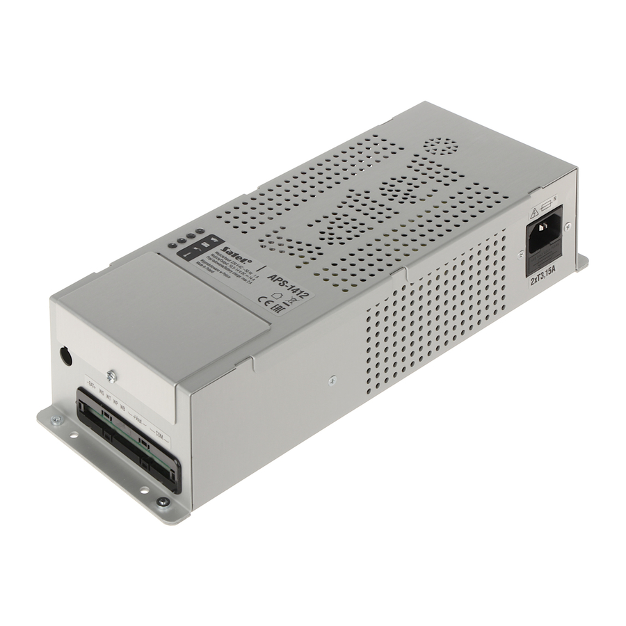
- Page 3 The APS-1412 switch mode power supply is designed for devices requiring 12 VDC nominal voltage. The power supply can be integrated e.g. with the following SATEL devices (shown in brackets is the required firmware version): ACCO-NT (v.1.10), ACX-220, ...
-
Page 4: Power Supply Description
APS-1412 SATEL Electronic short-circuit and overload protection of the power output. 2 Power supply description terminals cover. LEDs indicating the power supply status: – red LED – power output status: OFF – normal operation, current consumption up to14 A, flashing –... - Page 5 Fig. 3 shows the part of the power supply electronics board that is visible after removal of the cover (see Fig. 1). DIP-switches (see “Configuring the power supply”). connector for SATEL devices which are provided with a corresponding connection. MINI 15 A car fuse – battery charging circuit protection. Description of terminals –...
- Page 6 APS-1412 SATEL In the normal state, the OC type outputs are shorted to ground (0 V), but when a trouble occurs, the output is disconnected from ground. 2.2 Configuring the power supply You can configure the power supply working parameters by using the DIP switches 1, 2, 4 and 5 (see Table 1).
-
Page 7: Installation
The used batteries must not be discarded, but should be disposed of in accordance with the existing rules for environment protection. The sum of currents consumed by the devices to be supplied via the APS-1412 power supply may not exceed: ... - Page 8 3. Use the DIP switches to configure the power supply (see “Configuring the power supply”). 4. If the power supply is to be integrated with a SATEL device, use the cable delivered with the power supply to connect the power supply and the device. Pass the cable through the opening in the enclosure (Fig.
-
Page 9: Specification
SATEL APS-1412 3 Standard requirements for battery If the power supply is to be used in an alarm system which is to meet requirements of the EN 50131 standard for Grade 2, the battery should provide 12 hours of system operation in the event of mains power loss. - Page 10 APS-1412 SATEL Environmental class .........................II Operating temperature range................-10°C...+55°C Enclosure dimensions ................. 101 x 68 x 291 mm Weight..........................1.37 kg...
Need help?
Do you have a question about the APS-1412 and is the answer not in the manual?
Questions and answers