Table of Contents
Advertisement
Quick Links
Advertisement
Table of Contents

Related Manuals for Pilz PSEN 4.2a


Summary of Contents for Pilz PSEN 4.2a
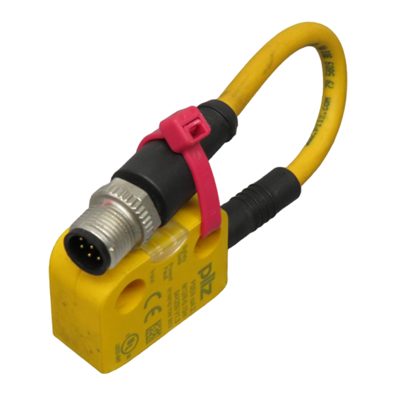
- Page 1 PSEN 4.2a/b/p/M12 PSEN sensor technology Operating Manual-22188-EN-02...
- Page 2 Preface This document is a translation of the original document. All rights to this documentation are reserved by Pilz GmbH & Co. KG. Copies may be made for internal purposes. Suggestions and comments for improving this documentation will be gratefully received.
-
Page 3: Table Of Contents
Teaching in the actuator Installation Parallel assembly Orthogonal assembly Adjustment Operation Error display through flashing codes Dimensions in mm PSEN cs4.2a, PSEN cs4.2b PSEN cs4.2p PSEN cs4.2 M12/8-0.15m Technical details Safety characteristic data Order reference Operating Manual PSEN 4.2a/b/p/M12 22188-EN-02... -
Page 4: Introduction
It also highlights areas within the text that are of particular importance. INFORMATION This gives advice on applications and provides information on special fea- tures. Operating Manual PSEN 4.2a/b/p/M12 22188-EN-02... -
Page 5: Safety Switch Psen Cs4.2
Supply voltage/fault 1 direction of actuation Connection types: – PSEN cs4.2a: Cable, 5 m – PSEN cs4.2b: Cable, 10 m – PSEN cs4.2p: 8 pin M8 connector – PSEN cs4.2 M12/8-0.15m: Connector 8 pin M12 Operating Manual PSEN 4.2a/b/p/M12 22188-EN-02... -
Page 6: Function Description
Safety inputs S11 and S21 are monitored for feasibility. A high signal can be present at the inputs at offset times; the low signal must be present at both inputs simultaneously (partial operation lock). Block diagram A1 A2 S11 S21 Input Receiver Actuator & Power 12 22 Operating Manual PSEN 4.2a/b/p/M12 22188-EN-02... -
Page 7: Operating Distances
: Assured release distance: 20,0 mm Lateral and vertical offset 8 10 10 mm Legend: : Hysteresis : Typical operating distance S : Typical release distance S : Offset in mm : Switching distance in mm : Response range Operating Manual PSEN 4.2a/b/p/M12 22188-EN-02... -
Page 8: Wiring
0 V UB Blue Do not connect The wire colour also applies for the cable available from Pilz as an accessory. Connection to evaluation devices Please note: The power supply must meet the regulations for extra low voltages with safe separation (SELV, PELV). -
Page 9: Single Connection
PSEN 4.2a/b/p/M12 Single connection Actuator Receiver Evaluation device Operating Manual PSEN 4.2a/b/p/M12 22188-EN-02... -
Page 10: Series Connection
Extension of delay-on de-energisation When several units are connected in series, the delay-on de-energisation time increases in direct proportion to the number of interconnected safety switches. Actuator Receiver Control system Actuator Receiver Actuator Receiver Evaluation device Operating Manual PSEN 4.2a/b/p/M12 22188-EN-02... -
Page 11: Connection To Pnoz X, Pnozpower, Pnozsigma, Pnozelog
PSENcode PNOZ PNOZ X2.8P PNOZ X4 PNOZ X8P PNOZ X9P n.c. PNOZ X3P PSENcode PNOZ PNOZ X3.10P PNOZ XV3P PNOZ X3.1P n.c. PNOZ s3 PSENcode PNOZ PNOZ s4 PNOZ s4.1 PNOZ s5 PNOZ X5 n.c. Operating Manual PSEN 4.2a/b/p/M12 22188-EN-02... - Page 12 PSEN 4.2a/b/p/M12 PNOZ X2.9P PSENcode PNOZ n.c. PNOZ X10.1 PSENcode PNOZ PNOZ X10.11P n.c. PNOZ e1.1p PSENcode PNOZ PNOZ e1vp PNOZ e6.1p PNOZ e6vp n.c. PNOZ e5.11p PSENcode PNOZ PNOZ e5.13p n.c. Operating Manual PSEN 4.2a/b/p/M12 22188-EN-02...
-
Page 13: Connection To Pnozmulti
The distance between two safety switches must be maintained (see Technical De- tails [ 20]). Safety switches and actuators Should not be exposed to heavy shock or vibration and Should not be used as a limit stop. Operating Manual PSEN 4.2a/b/p/M12 22188-EN-02... -
Page 14: Parallel Assembly
The inscribed area on the actuator (sensing face) should face the safety switch. Slide the actuator on to the screws. Align the safety switch and tighten the screws. Align the actuator and tighten the screws. Operating Manual PSEN 4.2a/b/p/M12 22188-EN-02... -
Page 15: Orthogonal Assembly
Orthogonal assembly Drill holes in the mounting surface (see mensions [ 19]) and cut threads in the holes for M4 screws. Use a screw to fix the safety switch in place. Operating Manual PSEN 4.2a/b/p/M12 22188-EN-02... - Page 16 Use the seals to close the screws' mounting holes on the actuator (4): Without UL approval (1): For UL approval Use the seals (3) to close the mounting holes on the sensing face of the safety switch. Operating Manual PSEN 4.2a/b/p/M12 22188-EN-02...
-
Page 17: Adjustment
1 2 3 4 5 6 7 8 9 10 11 12 13 14 15 16 Decimal error code 1 2 3 4 5 6 7 8 9 10 11 12 13 14 15 0 Operating Manual PSEN 4.2a/b/p/M12 22188-EN-02... - Page 18 Rectify wiring error at safety output 3x short tween safety output 12 and 24 3x short – 15x long – During operation, short circuit be- Rectify wiring error at safety output 3x short tween safety output 22 and 24 Operating Manual PSEN 4.2a/b/p/M12 22188-EN-02...
-
Page 19: Dimensions In Mm
PSEN 4.2a/b/p/M12 Dimensions in mm PSEN cs4.2a, PSEN cs4.2b 14, 4 14, 4 26, 4 PSEN cs4.2p 14, 4 14, 4 26, 4 Operating Manual PSEN 4.2a/b/p/M12 22188-EN-02... -
Page 20: Psen Cs4.2 M12/8-0.15M
-20 %/+20 % Output of external power supply 1,0 W 1,0 W (DC) Max. switching frequency 3 Hz 3 Hz Switching current per output 100 mA 100 mA Breaking capacity per output 2,4 W 2,4 W Operating Manual PSEN 4.2a/b/p/M12 22188-EN-02... - Page 21 In accordance with the standard EN 60068-2-14 EN 60068-2-14 Temperature range -25 - 70 °C -25 - 70 °C Storage temperature In accordance with the standard EN 60068-2-1/-2 EN 60068-2-1/-2 Temperature range -25 - 70 °C -25 - 70 °C Operating Manual PSEN 4.2a/b/p/M12 22188-EN-02...
- Page 22 Height 37,0 mm 37,0 mm Width 18,0 mm 18,0 mm 18,0 mm 18,0 mm Depth Weight of safety switch 205 g 380 g Weight of actuator 10 g 10 g Weight 215 g 390 g Operating Manual PSEN 4.2a/b/p/M12 22188-EN-02...
- Page 23 450 µs Switch-on delay After UB is applied 1,0 s 1,0 s Inputs typ. 13 ms 13 ms 20 ms 20 ms Inputs max. Actuator typ. 45 ms 45 ms Actuator max. 120 ms 120 ms Operating Manual PSEN 4.2a/b/p/M12 22188-EN-02...
- Page 24 8,0 mm Typical operating distance So 11,0 mm 11,0 mm Assured release distance Sar 20,0 mm 20,0 mm 14,0 mm 14,0 mm Typical release distance Sr Min. distance between safety 100 mm 100 mm switches Operating Manual PSEN 4.2a/b/p/M12 22188-EN-02...
-
Page 25: Safety Characteristic Data
A safety function's SIL/PL values are not identical to the SIL/PL values of the units that are used and may be different. We recommend that you use the PAScal software tool to calculate the safety function's SIL/PL values. Operating Manual PSEN 4.2a/b/p/M12 22188-EN-02... -
Page 26: Order Reference
8-pin M8 connector 541 260 PSEN cs4.2a (switch) Safety switch, uniquely cod- Cable, 5 m 541 261 PSEN cs4.2b (switch) Safety switch, uniquely cod- Cable, 10 m 541 262 PSEN cs4.1 Actuator, coded 541 180 Operating Manual PSEN 4.2a/b/p/M12 22188-EN-02... - Page 27 +49 711 3409-444 represented by our subsidiaries support@pilz.com and sales partners. Please refer to our homepage for further details or contact our headquarters. Pilz GmbH & Co. KG Felix-Wankel-Straße 2 73760 Ostfildern, Germany Telephone: +49 711 3409-0 Telefax: +49 711 3409-133 E-Mail: pilz.gmbh@pilz.de...
Need help?
Do you have a question about the PSEN 4.2a and is the answer not in the manual?
Questions and answers