Advertisement
Available languages
Available languages
Quick Links
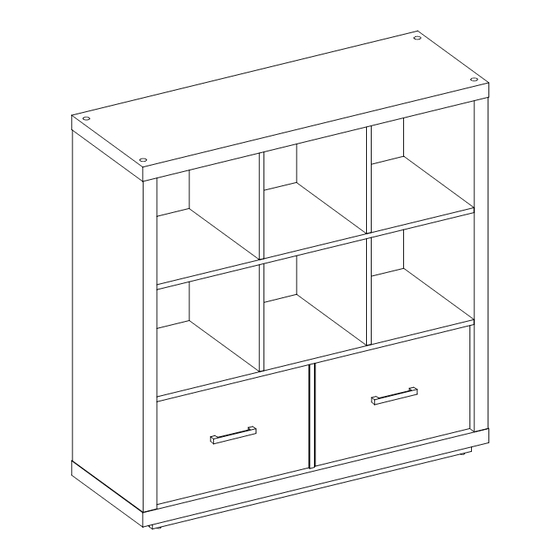
Steele Organizer with Drawers
If you have any questions regarding assembly or if parts are missing, DO NOT return this item to the
store where it was purchased. Please call our customer service number and have your instructions
and parts list ready to provide the model name, part name or factory number:
Pacific Standard Time: 8:30 a.m. - 4:30 p.m., Monday - Friday
Or visit our web site 24 hours a day, 7 days a week for product assistance at
THIS INSTRUCTION BOOKLET CONTAINS IMPORTANT SAFETY INFORMATION.
Stock # BH46-084-099-54
ADULT ASSEMBLY REQUIRED
www.whalenstyle.com
Or e-mail your request to parts@whalenfurniture.com
PLEASE READ AND KEEP FOR FUTURE REFERENCE.
Date 2016-09-24 Rev. 0001-A Factory: HESLTD
866-942-5362
LOT NUMBER:
DATE PURCHASED:
/
/
Advertisement

Related Manuals for Better Homes and Gardens BH46-084-099-54


Summary of Contents for Better Homes and Gardens BH46-084-099-54
- Page 1 LOT NUMBER: DATE PURCHASED: Steele Organizer with Drawers Stock # BH46-084-099-54 ADULT ASSEMBLY REQUIRED If you have any questions regarding assembly or if parts are missing, DO NOT return this item to the store where it was purchased. Please call our customer service number and have your instructions...
-
Page 2: Special Note
M A X I M U M R E C O M M E N D E D W E I G H T L O A D S MANUFACTURER: Whalen Furniture Manufacturing CATALOGUE: Steele Organizer with Drawers (BH46-084-099-54) MADE IN CHINA MAXIMUM LOAD 200 lb. - Page 3 IMPORTANT Before you begin: Open, identify and count all parts prior to assembly. Lay out parts on a flat and non- abrasive surface. You will need the parts identified on page 4 and 5 of this instruction manual. NOTE: IT IS VERY IMPORTANT TO USE GLUE WITH DOWELS. EXCESS GLUE CAN BE WIPED OFF WITH DAMP CLOTH.
- Page 4 Parts and Hardware List Please read completely through the instructions and verify that all listed parts and hardware are present before beginning assembly. A- Top Panel (Qty. 1) B- Left Side Panel (Qty. 1) C- Right Side Panel (Qty. 1) D- Bottom Panel (Qty.
- Page 5 Parts and Hardware List Please read completely through the instructions and verify that all listed parts and hardware are present before beginning assembly. (1) Small Cam Lock (2) Large Cam Lock (3) Cam Bolt (Qty. 12+1 extra) (Qty. 22+1 extra) (Qty.
- Page 6 Assembly Instructions Cam Bolt Small Cam Lock M6 x 30 mm Wood Dowel (6 used in this step) (6 used in this step) (2 used in this step) ③ ⑦ ① 1. Unpack the unit and confirm that you have all the hardware and required parts. Assembly the unit on a carpeted floor or the empty carton to avoid any scratch.
- Page 7 Assembly Instructions 5. Slide the Utility Drawer Bottom Panel (P) into the grooves between the Drawer Side Panels (M and N) until fully inserted into the Drawer Front (R).
- Page 8 Assembly Instructions M4 x 38 mm Screw (6 used in this step) ⑪ 6. Fasten one Drawer Back Panel (O) to the Drawer Side Panels (M and N) and Bottom Support (Q) with six 38 mm Screws (11). Make sure that Drawer Bottom Panel (P) fits securely into the groove of the Drawer Back Panel (O).
- Page 9 Assembly Instructions Handle Handle Bolt (1 used in this step) (2 used in this step) ⑬ ⑭ 7. Turn the assembled drawer upright. 8. Attach the Handle (13) to the outside of the Drawer Front (R) with two Handle Bolts (14). 9.
- Page 10 Assembly Instructions M8 x 30 mm Wood Dowel M4 x 50 mm Screw (12 used in this step) (12 used in this step) ⑫ ⑥ 10. Attach the Bottom Short Supports (K) between the Bottom Long Supports (J) with four 30 mm Wood Dowels (6).
- Page 11 Assembly Instructions Cam Bolt (22 used in this step) ③ 12. Securely screw the Cam Bolts (3) into the designated small holes on the Side Panels (B and C), the Bottom Panel (D) and the Lower Fixed Shelf (F) using a Phillips screwdriver.
- Page 12 Assembly Instructions Large Cam Lock M8 x 30 mm Wood Dowel (4 used in this step) (2 used in this step) ② ⑥ 13. Attach the Back Panel (L) to the Lower Fixed Shelf (F) with two 30 mm Wood Dowels (6) and four Large Cam Locks (2) (Refer to page 3 on Cam Lock system operation supplement).
- Page 13 Assembly Instructions Large Cam Lock M8 x 30 mm Wood Dowel (2 used in this step) (2 used in this step) ② ⑥ 14. Attach the Drawer Divider (H) to the Lower Fixed Shelf (F) with two 30 mm Wood Dowels (6) and two Large Cam Locks (2).
- Page 14 Assembly Instructions M8 x 30 mm Wood Dowel M4 x 50 mm Screw (4 used in this step) (4 used in this step) ⑫ ⑥ 15. Attach two Middle Divider Panels (I) to the Lower Fixed Shelf (F) with four 30 mm Wood Dowels (6) and four 50 mm Screws (12).
- Page 15 Assembly Instructions M8 x 60 mm Small Wood Dowel (8 used in this step) ⑤ 16. Attach two Upper Divider Panels (G) and Upper Fixed Shelf (E) to the assembled Middle Divider Panels (I) with eight 60 mm Small Wood Dowels (5).
- Page 16 Assembly Instructions Large Cam Lock M8 x 30 mm Wood Dowel (12 used in this step) (10 used in this step) ② ⑥ 17. Attach the Right Side Panel (C) to the Fixed Shelves (E and F) and the Back Panel (L) with five 30 mm Wood Dowels (6) and six Large Cam Locks (2).
- Page 17 Assembly Instructions Large Cam Lock M8 x 30 mm Wood Dowel M15x 60 mm Large Wood Dowel (4 used in this step) (4 used in this step) (4 used in this step) ② ⑥ ④ 19. Insert four 60 mm Large Wood Dowels (4) into the bottom holes on the Side Panels (B and C) and insert four 30 mm Wood Dowels (6) into the bottom holes on the Drawer Divider (H) and the Back Panel (L).
- Page 18 Assembly Instructions 2-1/4” Bolt (4 used in this step) ⑧ Flat Washer Lock Washer M4 x 50 mm Screw (4 used in this step) (4 used in this step) (2 used in this step) ⑫ ⑨ ⑩ 20. Secure the Bottom Panel (D) to the Side Panels (B and C) with four 2-1/4” Bolts (8) and four Washers (9 and 10).
- Page 19 Assembly Instructions M8 x 60 mm Small Wood Dowel (8 used in this step) ⑤ Plastic Cap M15x 60 mm Large Wood Dowel (4 used in this step) (4 used in this step) ⑯ ④ Flat Washer Lock Washer 2-1/4” Bolt (4 used in this step) (4 used in this step) (4 used in this step)
- Page 20 Assembly Instructions 25. Ask for assistance to stand the unit upright. 26. Insert the assembled drawers into the frame. Extend the Ball Bearing Slide Tracks on the Side Panels (B and C) all the way forward (including ball bearing cart). Then align the Slide Runners on the assembled drawer with the Slide Tracks and push the drawer carefully inside until it stops.
- Page 21 Assembly Instructions 28. Position the unit at the desired location against a wall. 29. Follow the instructions printed on the plastic bag containing the tipping restraint hardware to attach the tip-over restraints to the unit and the wall. NOTE: The tipping restraint hardware included is for drywall construction. It will be necessary to drill holes for the wall anchors.
-
Page 22: Care And Maintenance
Care and Maintenance Use a soft, clean cloth that will not scratch the surface when dusting. Use of furniture polish is not necessary. Should you choose to use polish, test first in an inconspicuous area. Using solvents of any kind on your furniture may damage your furniture’s finish. Never use water to clean your furniture as it may cause damage to the finish. - Page 23 LOTE NÚMERO: FECHA COMPRA: / Organizador Steele con cajones Serie # BH46-084-099-54 ENSAMBLE REQUERIDO POR ADULTO Si tiene alguna pregunta acerca del ensamble o si alguna parte está faltante, no retorne este producto a la tienda en que lo compró. Por favor llame a nuestro departamento de ayuda al cliente teniendo su instructivo y lista de partes para proveer el modelo, nombre de parte o el número de fábrica:...
- Page 24 M Á X I M A C A R G A R E C O M E N D A D A FABRICANTE: Whalen Furniture Manufacturing CATALOGO: Organizador Steele con cajones (BH46-084-099-54) HECHO EN CHINA MÁXIMA CARGA 200 lb. (90.7 kg) MÁXIMA CARGA 50 lb.
- Page 25 IMPORTANTE Antes de comenzar: Abra, identifique y cuente todas las partes antes del ensamble. Coloque las piezas sobre una superficie plana y no abrasiva. Tendrá que las partes identificadas en la página 4 y 5 de este manual de instrucciones. NOTA: ES MUY IMPORTANTE PARA EL USO DE GOMA CON LOS PERNSO DE MADERA.
- Page 26 Lista de Partes y Artículos de Ferretería Por favor, lea completamente todas las instrucciones y verifique que todas las piezas mencionadas y el material están presentes antes de comenzar el montaje. A- Panel superior (Cant. 1) B- Panel izquierdo (Cant. 1) C- Panel derecho (Cant.
- Page 27 Lista de Partes y Artículos de Ferretería Por favor, lea completamente todas las instrucciones y verifique que todas las piezas mencionadas y el material están presentes antes de comenzar el montaje. (1) Tuerca de fijación chica (2) Tuerca de fijación grande (3) Tornillo de fijación (Cant.
-
Page 28: Instrucciones De Ensamble
Instrucciones de ensamble Perno M6 x 30 mm de madera Tornillo de fijación Tuerca de fijación chica (2 usados en este paso) (6 usados en este paso) (6 usados en este paso) ③ ⑦ ① 1. Desempacar la unidad y confirmar que todas las partes estan completas antes de tirar la caja y material de empaque. - Page 29 Instrucciones de ensamble 5. Deslice el panel inferior del cajón de utilidad (P) en las ranuras entre los paneles laterales del cajón (M y N) hasta que esté completamente insertado en el frente del cajón (R).
- Page 30 Instrucciones de ensamble Tornillo M4 x 38 mm (6 usados en este paso) ⑪ 6. Fijar un panel trasero del cajón (O) en los paneles laterales del cajón (M y N) y el soporte inferior (Q) con seis tornillos de 38 mm (11). Asegúrese de que el panel inferior de cajón (P) encaja perfectamente en la ranura del panel trasero del cajón (O).
- Page 31 Instrucciones de ensamble Manija Tornillo de maniija (1 usado en este paso) (2 usados en este paso) ⑬ ⑭ 7. Gire el cajón en posición vertical. 8. Adjunte las manijas (13) en la parte exterior del frente de cajón (R) con 2 tornillos de manija (14). 9.
- Page 32 Instrucciones de ensamble Perno M8 x 30 mm de madera Tornillo M4 x 50 mm (12 usados en este paso) (12 usados en este paso) ⑫ ⑥ 10. Coloque los soportes inferiores cortos (K) entre los soportes inferiores largos (J) con cuatro pernos de 30 mm de madera (6).
- Page 33 Instrucciones de ensamble Tornillo de fijación (22 usados en este paso) ③ 12. Asegure los tornillos de fijación (3) en los orificios pequeños designados en los paneles laterales (B y C), el panel inferior (D) y la repisa inferior fija (F) con un desarmador estrella.
- Page 34 Instrucciones de ensamble Tuerca de fijación grande Perno M8 x 30 mm de madera (4 usados en este paso) (2 usados en este paso) ② ⑥ 13. Fijar el panel posterior (L) a la repisa inferior fija (F) con dos pernos de 30 mm de madera (6) y cuatro tuercas de fijación grandes (2) (consulte la página 3 de la tuerca de fijación y su operación).
- Page 35 Instrucciones de ensamble Tuerca de fijación grande Perno M8 x 30 mm de madera (2 usados en este paso) (2 usados en este paso) ② ⑥ 14. Una el divisor de cajón (H) para la repisa inferior fija (F) con dos pernos de 30 mm de madera (6) y dos tuercas de fijación grandes (2).
- Page 36 Instrucciones de ensamble Perno M8 x 30 mm de madera Tornillo M4 x 50 mm (4 usados en este paso) (4 usados en este paso) ⑫ ⑥ 15. Adjuntar 2 divisores medios (I) a la repisa fija inferior (F) con 4 pernos de 30 mm de madera (6) y 4 tornillos de 50 mm (12).
- Page 37 Instrucciones de ensamble Perno M8 x 60 mm de madera (8 usados en este paso) ⑤ 16. Coloque dos paneles divisorios superiores (G) y repisa fija superior (E) a los paneles divisorios medios ensamblados (I) con ocho pernos de 60 mm de madera (5).
- Page 38 Instrucciones de ensamble Tuerca de fijación grande Perno M8 x 30 mm de madera (12 usados en este paso) (10 usados en este paso) ② ⑥ 17. Coloque el panel lateral derecho (C) a las repisas fijas (E y F) y el panel posterior (L) con cinco pernos de 30 mm de madera (6) y seis tuercas de fijación grandes (2).
- Page 39 Instrucciones de ensamble Tuerca de fijación grande Perno M8 x 30 mm Perno M15x 60 mm de madera (4 usados en este paso) (4 usados en este paso) (4 usados en este paso) ② ⑥ ④ 19. Inserte cuatro pernos grandes de 60 mm de madera (4) en los orificios inferiores de los paneles laterales (B y C) e inserte cuatro pernos de 30 mm de madera (6) en los orificios inferiores del divisor de cajón (H) y el panel posterior (L).
- Page 40 Instrucciones de ensamble Tornillo 2-1/4” (4 usados en este paso) ⑧ Arandela plana Arandela de presión Tornillo de M4 x 50 mm (4 usados en este paso) (4 usados en este paso) (2 usados en este paso) ⑫ ⑨ ⑩ 20.
- Page 41 Instrucciones de ensamble Perno M8 x 60 mm de madera (8 usados en este paso) ⑤ Tapón plástico Perno M15x 60 mm de madera usados en este paso (4 usados en este paso) ⑯ ④ Arandela plana Arandela de presión Tornillo de 2-1/4”...
- Page 42 Instrucciones de ensamble 25. Pedir ayuda a colocar la unidad en posición vertical. 26. Introducir el cajón montado en el bastidor. Extender el carrito con baleros de las correderas de los paneles laterales (B y C) completamente hacia adelante (incluyendo el carrito interior). Alinee los complementos de correderas del cajón ensamblado con las de la unidad y empuje el cajón con cuidado en el interior hasta que se detenga.
- Page 43 Instrucciones de ensamble 28. Posición de la unidad en la posición deseada contra una pared. 29. Siga las instrucciones impresas en la bolsa de plástico que contiene el hardware de la restricción de inflexión para unir las restricciones vuelco a la unidad y la pared. NOTA: El juego de restricción de movimiento suministrado es para paredes de tablaroca.
-
Page 44: Mantenimiento Y Cuidados
Mantenimiento y Cuidados Use una toalla suave y limpia para evitar daños y rayaduras. El uso de cera para pulir muebles no es necesario. Si desea usar cera pruebe en un área que no sea visible para revisar su funcionamiento. Usar solventes de cualquier tipo puede dañar el acabado del mueble.
Need help?
Do you have a question about the BH46-084-099-54 and is the answer not in the manual?
Questions and answers