Advertisement
Quick Links
Better
omes
H
and Gardens
®
THIS INSTRUCTION BOOKLET CONTAINS
IMPORTANT SAFETY INFORMATION. PLEASE
READ AND KEEP FOR FUTURE REFERENCE.
Please Recycle
Recicle Por Favor
5683215WCOM
DO NOT RETURN PRODUCT TO THE STORE
STOP
Individual stores do not stock parts.
Date of Purchase
___ / ___ / ___
If a part is missing or damaged, visit our website or call our toll-free
customer service line. We will gladly ship your replacement parts
FREE of charge.
Need Parts or Assistance?
WWW.AMERIWOOD.COM/PARTS
For prompt, reliable service please have your assembly manual ready.
Recommended # of people needed for assembly: 1
(however it is always better to have an extra hand.)
Estimated assembly time is 1 hour.
Se localizan las traducciones españolas en el centro de este
manual.
or call toll free:
1-800-489-3351
B345683215WCOM 3
Advertisement

Related Manuals for Better Homes and Gardens 5683215WCOM


Summary of Contents for Better Homes and Gardens 5683215WCOM
- Page 1 Better 5683215WCOM omes and Gardens ® DO NOT RETURN PRODUCT TO THE STORE STOP Individual stores do not stock parts. Date of Purchase ___ / ___ / ___ If a part is missing or damaged, visit our website or call our toll-free customer service line.
- Page 3 PARTS Parts shown are the base cabinet of your model. Drawer is shown on next page. Please note, some parts are labeled with a sticker and some parts have a letter stamped on a raw edge. This piece is paperboard construction. It is not made from wood but is required for the assembly of your unit.
- Page 4 PARTS Parts shown are for the drawer of your model. Please note, some parts are labeled with a sticker and some parts have a letter stamped on a raw edge. Parts List ITEM PART NUMBER DESCRIPTION 35683215060 DRAWER FRONT 35683302070 LEFT DRAWER SIDE 35683302100 RIGHT DRAWER SIDE...
- Page 5 PARTS x 16 #A22920 #A11600 #A22570 #A22510 #A22910 #A21660 #A17400 #A12850 connector cam lock cam bolt connector bolt wood dowel 1" pan head 8-32 x 7/8" bolt 1-1/4" flat head #A12120 #A11080 #A21110 #A54200 #A52480 7/16" pan head 7/16" flat head nail drawer bracket knob...
- Page 6 This illustration shows how the CAM fastening system works. Esta ilustración muestra el sistema de fijación de leva y como funciona. Tighten to fully seat. Do not over tighten. Proper orientation of cam. Apriétese a totalmente asiento. No La orientación apropiada de leva. haga encima de apriétese.
- Page 7 Important: When using a power drill or power screwdriver for screwing, please be aware to slow down and stop when screw is tight. Failure to do so may result in stripping the screw. You will need to tap the connector (3) with a hammer to fully insert.
- Page 8 You will use the larger holes in the rear legs (R) for the connector bolts (4). The rear legs (R) has holes in the front and rear surface. B345683215WCOM 3 8 /34 ?? www.ameriwood.com ??
- Page 9 Press the front and rear legs (Q&R) onto the left panel (A) so the connector bolts (4) engage the connectors (3). Turn the screw in the center of the connector (3) clockwise to lock in place. Small holes in rear surface. Los agujeros pequeños en superficie posterior.
- Page 10 Press the front and rear legs (Q&R) onto the right panel (B) so the connector bolts (4) engage the connectors (3). Turn the screw in the center of the connector (3) clockwise to lock in place. Small holes in rear surface. Los agujeros pequeños en superficie posterior.
- Page 11 Proper orientation of CAM LOCK Posición correcta de la cerradura de leva. B345683215WCOM 3 11 /34 ?? www.ameriwood.com ??
- Page 12 Proper orientation of CAM LOCK Posición correcta de la cerradura de leva. B345683215WCOM 3 12 /34 ?? www.ameriwood.com ??
- Page 13 Attach the upper side molding (H) and lower rail (I) to the left panel (A) as shown with screws (6). Finished Edge Borde Acabado Be sure the top edge of the upper side molding (H) is flush with the top edge of the left panel (A). Be sure the bottom edge of the lower rail (I) is flush with the bottom edge of the left panel (A).
- Page 14 Attach the upper side molding (H) and lower rail (I) to the right panel (B) as shown with screws (6). Finished Edge Borde Acabado Be sure the top edge of the upper side molding (H) is flush with the top edge of the right panel (B). Be sure the bottom edge of the lower rail (I) is flush with the bottom edge of the right panel (B).
- Page 15 Position the left panel rail (N) as shown. Attach the left panel rail (N) to the left panel (A) with screws (6) as shown. If needed loosen screws, make needed adjustment of rail and re-tighten. B345683215WCOM 3 15 /34 ?? www.ameriwood.com ??
- Page 16 Position the right panel rail (O) as shown. Attach the right panel rail (O) to the right panel (B) with screws (6) as shown. If needed loosen screws, make needed adjustment of rail and re-tighten. B345683215WCOM 3 16 /34 ?? www.ameriwood.com ??
- Page 17 B345683215WCOM 3 17 /34 ?? www.ameriwood.com ??
- Page 18 Proper orientation of CAM LOCK Posición correcta de la cerradura de leva. B345683215WCOM 3 18 /34 ?? www.ameriwood.com ??
- Page 19 Proper orientation of CAM LOCK Posición correcta de la cerradura de leva. You will need to tap the connector (3) with a hammer to fully insert. Be sure the connector is positioned as shown before pushing into holes. B345683215WCOM 3 19 /34 ?? www.ameriwood.com ??
- Page 20 Turn screw clockwise to lock in place. Gire hacia la derecha el tornillo para bloquear en su lugar. End View Vista Final B345683215WCOM 3 20 /34 ?? www.ameriwood.com ??
- Page 21 Turn screw clockwise to lock in place. Gire hacia la derecha el tornillo para bloquear en su lugar. You will need to tap the connector (3) with a hammer to fully insert. Be sure the connector is positioned as shown before pushing into holes.
- Page 22 Attach the stringer (M) and bottom (D) to left panel (A) first, then attach the right panel (B) to the stringer (M) and bottom (D). LOCK UNLOCK APRETAR DESAPRETAR B345683215WCOM 3 22 /34 ?? www.ameriwood.com ??
- Page 23 LOCK UNLOCK APRETAR DESAPRETAR B345683215WCOM 3 23 /34 ?? www.ameriwood.com ??
- Page 24 IMPORTANT! THE BACK PANEL IS A STRUCTURAL PART OF THIS UNIT AND MUST BE INSTALLED PROPERLY. Carefully place unit on its front side. Position the back panel (S) as shown. Using eight screws (9), attach as shown. DO NOT tighten the screws at this time. B345683215WCOM 3 24 /34 ?? www.ameriwood.com ??
- Page 25 WARNING Please make sure that the Backs are attached securely. All nails must be driven into the parts straight and tightened firmly. Failure to do so could cause instability, product collapse, and/or serious injury. AVERTISSEMENT S’il-vous-plaît assurez-vous que les PANNEAUX ARRIÈRES sont attachés solidement.
- Page 26 Lay the drawer sides down on a flat hard surface. Carefully line up the drawer bracket with the holes in the drawer side as shown. Using a hammer, tap each drawer bracket stem part way into each hole. Repeat this process until the drawer bracket is fully seated on the drawer side.
- Page 27 Finished Edge Borde Acabado B345683215WCOM 3 27 /34 ?? www.ameriwood.com ??
- Page 28 B345683215WCOM 3 28 /34 ?? www.ameriwood.com ??
- Page 29 Finished Surface Superficie Acabado B345683215WCOM 3 29 /34 ?? www.ameriwood.com ??
- Page 30 B345683215WCOM 3 30 /34 ?? www.ameriwood.com ??
- Page 31 B345683215WCOM 3 31 /34 ?? www.ameriwood.com ??
- Page 32 Notice, the drawer bracket holes are slotted. Drawer front can be adjusted by loosening screws, making needed adjustments and retightening screws. Tenga en cuenta que los orificios de soporte del cajón se ranuran. El frente del cajón se puede ajustar aflojando tornillos, haciendo los ajustes necesarios y volver a apretar los tornillos.
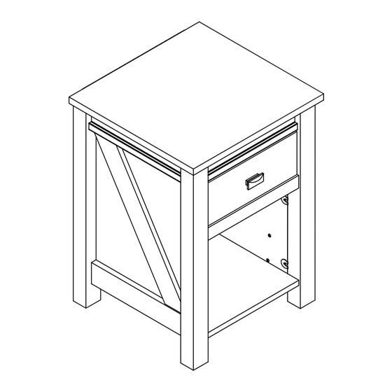
- Page 33 MAXIMUM LOADS – CARGA MAXIMA - CHARGES MAXIMALES This unit has been designed to support the maximum loads shown. Exceeding these load limits could cause sagging, instability, product collapse, and/or serious injury. 40 lbs. Esta unidad ha sido diseñada para 18.1 kg.
- Page 34 Certificate of Conformity 1. This certificate applies to the Dorel Home Furnishings, Inc. product identified by this instruction manual. 2. This certificate applies to compliance of this product with the CPSC Ban on Lead-Containing Paint (16 CFR 1303). 3. This product is distributed by: Dorel Home Furnishings, Inc. 410 East First Street South Wright City, MO 63390 636-745-3351...
Need help?
Do you have a question about the 5683215WCOM and is the answer not in the manual?
Questions and answers