Better Homes and Gardens Steele Series Assembly Manual
Audio video tower
Hide thumbs
Also See for Steele Series:
- Assembly manual (68 pages) ,
- Assembly manual (44 pages) ,
- Assembly manual (36 pages)
Advertisement
Available languages
Available languages
Quick Links
Download this manual
See also:
Assembly Manual
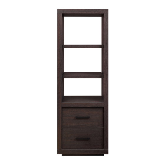
Steele Audio Video Tower
If you have any questions regarding assembly or if parts are missing, DO NOT return this item to the
store where it was purchased. Please call our customer service number and have your instructions
and parts list ready to provide the model name, part name or factory number:
Pacific Standard Time: 8:30 a.m. - 4:30 p.m., Monday - Friday
Or visit our web site 24 hours a day, 7 days a week for product assistance at
THIS INSTRUCTION BOOKLET CONTAINS IMPORTANT SAFETY INFORMATION.
Stock # BH46-084-099-53
ADULT ASSEMBLY REQUIRED
www.whalenstyle.com
Or e-mail your request to parts@whalenfurniture.com
PLEASE READ AND KEEP FOR FUTURE REFERENCE.
Date 2017-03-22 Rev. 0001-B Factory: HESLTD
866-942-5362
LOT NUMBER:
DATE PURCHASED:
/
/
Advertisement

Related Manuals for Better Homes and Gardens Steele Series


Summary of Contents for Better Homes and Gardens Steele Series
- Page 1 LOT NUMBER: DATE PURCHASED: Steele Audio Video Tower Stock # BH46-084-099-53 ADULT ASSEMBLY REQUIRED If you have any questions regarding assembly or if parts are missing, DO NOT return this item to the store where it was purchased. Please call our customer service number and have your instructions and parts list ready to provide the model name, part name or factory number: 866-942-5362 Pacific Standard Time: 8:30 a.m.
-
Page 2: Special Note
M A X I M U M R E C O M M E N D E D W E I G H T L O A D S MANUFACTURER: Whalen Furniture Manufacturing CATALOGUE: Steele Audio Video Tower (BH46-084-099-53) MADE IN CHINA MAXIMUM LOAD 50 lb. - Page 3 IMPORTANT Before you begin: Open, identify and count all parts prior to assembly. Lay out parts on a flat and non- abrasive surface. You will need the parts identified on page 4 of this instruction manual. NOTE: IT IS VERY IMPORTANT TO USE GLUE WITH DOWELS. EXCESS GLUE CAN BE WIPED OFF WITH DAMP CLOTH.
- Page 4 Parts and Hardware List Please read completely through the instructions and verify that all listed parts and hardware are present before beginning assembly. A- Top Panel (Qty. 1) B- Left Side Panel (Qty. 1) C- Right Side Panel (Qty. 1) D- Bottom Panel (Qty.
- Page 5 Assembly Instructions M4 x 50 mm Screw M8 x 30 mm Wood Dowel (8 used in this step) (12 used in this step) ⑤ ④ 1. Unpack the unit and confirm that you have all the hardware and required parts. Assembly the unit on a carpeted floor or the empty carton to avoid any scratch.
- Page 6 Assembly Instructions Cam Bolt (8 used in this step) ② 4. Securely screw the Cam Bolts (2) into the designated small holes on the Top Panel (A) and the Side Panels (B and C) using a Phillips screwdriver.
- Page 7 Assembly Instructions M3 x 12 mm Screw Door Stopper (2 used in this step) (1 used in this step) ⑨ ⑩ 5. Using the pilot holes as a guide, attach the Door Stopper (10) to the Fixed Shelf (E) with two 12 mm Screws (9) as shown.
- Page 8 Assembly Instructions Cam Lock M8 x 30 mm Wood Dowel (4 used in this step) (4 used in this step) ① ④ 6. Attach the Fixed Shelf (E) to the Side Panels (B and C) with four 30 mm Wood Dowels (4) and four Cam Locks (1) (Refer to page 3 on Cam Lock system operation supplement).
- Page 9 Assembly Instructions Cam Lock M15x 60 mm Wood Dowel (4 used in this step) (4 used in this step) ① ③ 7. Attach the Top Panel (A) to the Side Panels (B and C) with four 60 mm Wood Dowels (3) and four Cam Locks (1).
- Page 10 Assembly Instructions M15x 60 mm Wood Dowel M4 x 50 mm Wood Screw (4 used in this step) (4 used in this step) ③ ⑤ 8. Attach the Bottom Panel (D) to the Side Panels (B and C) with four 60 mm Wood Dowels (3) and four 50 mm Wood Screws (5).
- Page 11 Assembly Instructions M3.5 x 15 mm Washer Head Screw (14 used in this step) ⑬ NOTE: We recommend attaching the back panel with the screws at the corners first. 9. Now, go back and tighten all cam locks and screws. Make sure that all the parts are tight and there are no gaps between the parts.
- Page 12 Assembly Instructions Handle Handle Bolt (2 used in this step) (4 used in this step) ⑦ ⑧ 11. Attach the Handles (7) to the outside of the Door Panel (I) with four Handle Bolts (8).
- Page 13 Assembly Instructions 12. Stand the assembled unit upright. 13. Pick up the Door (I) and attach the extended Hinge Arms to the Hinge Bases installed on the Left Side Panel (B). Loosen the bolt on the back of Hinge Base for an easy fit. Align and insert the “U” slot on Hinge Arm under the bolt head on the back of Hinge Base.
- Page 14 Assembly Instructions Shelf Pin (12 used in this step) ⑥ 15. Insert the Shelf Pins (6) into the desired holes in the sides of the compartments. Make sure you place the four Shelf Pins in the same level so the shelf is not tilted. Tilt and rest the Adjustable Shelves (F and K) onto the Shelf Pins (6) with the end notches of the Shelf fit onto the Shelf Pins properly.
- Page 15 Assembly Instructions Cam Lock Cover Rubber Bumper (4 used in this step) (1 used in this step) ⑫ ⑪ 16. Peel off one Rubber Bumper (11) from the bumper card and stick it at the outer corner of the Door (I) where it comes in contact with the Door Stopper (10).
- Page 16 Assembly Instructions 18. Position the unit at the desired location against a wall. 19. Follow the instructions printed on the plastic bag containing the tipping restraint hardware to attach the tip-over restraints to the unit and the wall. NOTE: The tipping restraint hardware included is for drywall construction. It will be necessary to drill holes for the wall anchors.
-
Page 17: Care And Maintenance
Care and Maintenance Use a soft, clean cloth that will not scratch the surface when dusting. Use of furniture polish is not necessary. Should you choose to use polish, test first in an inconspicuous area. Using solvents of any kind on your furniture may damage your furniture’s finish. Never use water to clean your furniture as it may cause damage to the finish. - Page 19 LOTE NÚMERO: FECHA DE COMPRA: / / Torre Audio Video Steele Serie # BH46-084-099-53 ENSAMBLE REQUERIDO POR ADULTO Si tiene alguna pregunta acerca del ensamble o si alguna parte está faltante, no retorne este producto a la tienda en que lo compró. Por favor llame a nuestro departamento de ayuda al cliente teniendo su instructivo y lista de partes para proveer el modelo, nombre de parte o el número de fábrica: 866-942-5362 Hora Estándar del Pacífico: 8:30 a.m.
- Page 20 M Á X I M O S P E S O S R E C O M E N D A D O S FABRICANTE: Whalen Furniture Manufacturing CATALOGO: Torre audio/video Steele (BH46-084-099-53) HECHO EN CHINA MÁXIMA CARGA 50 lb. (22.6 kg) ESTA UNIDAD DEBE UTILIZARSE CON LOS PESOS MÁXIMOS INDICADOS.
- Page 21 IMPORTANTE Antes de comenzar: Abra, identifique y cuente todas las partes antes del ensamble. Coloque las piezas sobre una superficie plana y no abrasiva. Tendrá que las partes identificadas en la página 4 de este manual de instrucciones. NOTA: ES MUY IMPORTANTE PARA EL USO DE GOMA CON LOS PERNSO DE MADERA. EL. EXCESO DE PEGAMENTO SE PUEDE LIMPIAR CON UN PAÑO HÚMEDO.
- Page 22 Lista de partes y material de ferretería Por favor lea completamente las instrucciones y verifique que estén todas las partes antes de iniciar el ensamblado A- Panel superior (Cant. 1) B- Panel lateral izq. (Cant. 1) C- Panel lateral der. (Cant. 1) D- Panel inferior (Cant.
-
Page 23: Instrucciones De Ensamble
Instrucciones de ensamble Tornillo M4 x 50 mm Perno M8 x 30 mm de madera (8 usados en este paso) (12 usados en este paso) ⑤ ④ 1. Desempacar la unidad y confirmar que se tiene todo el material de ferretería y partes requeridas. Ensamblar la unidad en un piso alfombrado o en el cartón vacío para evitar rasguños. - Page 24 Instrucciones de ensamble Tornillo de fijación (8 usados en este paso) ② 4. Adjuntar los tornillos de fijación (2) en los orificios pequeños designados en el panel superior (A) y los paneles laterales (B y C) con un desarmador estrella.
- Page 25 Instrucciones de ensamble Tornillo M3 x 12 mm Tope de puerta (2 usados en este paso) (1 usado en este paso) ⑨ ⑩ 5. Usar los orificios piloto como guía, coloque el tope de la puerta (10) a la repisa fija (E) con dos tornillos de 12 mm (9) como se muestra.
- Page 26 Instrucciones de ensamble Tuerca de fijación M8 x 30 mm de madera (4 usados en este paso) (4 usados en este paso) ① ④ 6. Coloque la repisa fija (E) a los paneles laterales (B y C) con cuatro pernos de 30 mm de madera (4) y cuatro tuercas de fijación (1) (Consulte la página 3 del sistema de tuerca de fijación y su operación).
- Page 27 Instrucciones de ensamble Tuerca de fijación Perno M15x 60 mm de madera (4 usados en este paso) (4 usados en este paso) ① ③ 7. Coloque el panel superior (A) a los paneles laterales (B y C) con cuatro pernos de 60 mm de madera (3) y cuatro tuercas de fijación (1).
- Page 28 Instrucciones de ensamble Perno M15x 60 mm de madera Tornillo M4 x 50 mm para madera (4 usados en este paso) (4 usados en este paso) ③ ⑤ 8. Una el panel inferior (D) a los paneles laterales (B y C) con cuatro pernos de 60 mm de madera (3) y cuatro tornillos para madera de 50 mm (5).
- Page 29 Instrucciones de ensamble Tornillo de M3.5 x 15 mm cabeza especial (14 usados en este paso) ⑬ NOTA: Se recomienda colocar el panel posterior con los tornillos en las esquinas primero. 9. Ahora, volver atrás y apretar todos las tuercas de fijación y tornillos. Asegúrese de que todas las partes estén apretados y que no haya espacios entre las partes.
- Page 30 Instrucciones de ensamble Manija Tornillo de manija (2 usados en este paso) (4 usados en este paso) ⑦ ⑧ 11. Fije las manijas (7) hacia el exterior del panel de la puerta (I) con cuatro tornillos para manija (8).
- Page 31 Instrucciones de ensamble 12. Poner la unidad en posición vertical. 13. Levante la puerta (I) y una los brazos extendidos de bisagra a las bases de bisagra instaladas en el panel lateral izquierdo (B). Aflojar el tornillo en la parte posterior de la articulación de base para tener un ajuste fácil.
- Page 32 Instrucciones de ensamble Soporte de repisa (12 usados en este paso) ⑥ 15. Inserte los soportes de repisa (6) en los orificios deseados en los lados de los compartimentos. Asegúrese de colocar los cuatro soportes de repisa en el mismo nivel por lo que la repisa no quede inclinada.
- Page 33 Instrucciones de ensamble Tapa de tuerca Tope plástico (4 usados en este paso) (1 usado en este paso) ⑫ ⑪ 16. Despegue el tope plástico (11) y pegarlo en la esquina exterior de la puerta (I) donde entra en contacto con el tope de la puerta (10).
- Page 34 Instrucciones de ensamble 18. Posicionar la unidad en el lugar deseado cerca de la pared. 19. Siga las instrucciones impresas en la bolsa de plástico que contiene el juego de restricción de movimiento para unir las restricciones vuelco a la unidad y la pared. NOTA: El juego de restricción de movimiento suministrado es para la construcción de paredes de tablaroca.
-
Page 35: Mantenimiento Y Cuidados
Mantenimiento y Cuidados Use una toalla suave y limpia para evitar daños y rayaduras. El uso de cera para pulir muebles no es necesario. Si desea usar cera pruebe en un área que no sea visible para revisar su funcionamiento. Usar solventes de cualquier tipo puede dañar el acabado del mueble.
Need help?
Do you have a question about the Steele Series and is the answer not in the manual?
Questions and answers