Toro Reelmaster 3555 Operator's Manual
Traction unit
Hide thumbs
Also See for Reelmaster 3555:
- Operator's manual (112 pages) ,
- Operator's manual (56 pages) ,
- Operator's manual (24 pages)
Table of Contents
Advertisement
Quick Links
Advertisement
Table of Contents

Related Manuals for Toro Reelmaster 3555


Summary of Contents for Toro Reelmaster 3555
- Page 1 Form No. 3432-531 Rev A Reelmaster ® 3555, 3575, and 3550 Traction Unit Model No. 03820—Serial No. 403446001 and Up Model No. 03821—Serial No. 403446001 and Up Model No. 03910—Serial No. 403446001 and Up *3432-531* A Register at www.Toro.com. Original Instructions (EN)
- Page 2 It is a violation of California Public Resource Code additional information, contact an Authorized Service Section 4442 or 4443 to use or operate the engine on Dealer or Toro Customer Service and have the model any forest-covered, brush-covered, or grass-covered and serial numbers of your product ready.
-
Page 3: Table Of Contents
Contents Draining the Water Separator ......44 Changing the Fuel Filter Canister...... 44 Bleeding Air from the Injectors ......44 Safety ............... 4 Electrical System Maintenance ......45 General Safety ........... 4 Electrical System Safety ........45 Engine-Emission Certification......4 Servicing the Battery......... -
Page 4: Safety
Safety This machine has been designed in accordance with EN ISO 5395 (when you complete the setup procedures) and ANSI B71.4-2017. General Safety This product is capable of amputating hands and feet and of throwing objects. • Read and understand the contents of this Operator’s Manual before starting the engine. -
Page 5: Safety And Instructional Decals
Safety and Instructional Decals Safety decals and instructions are easily visible to the operator and are located near any area of potential danger. Replace any decal that is damaged or missing. decal133-8062 decal110-9642 133-8062 110-9642 1. Stored energy hazard—read the Operator's Manual. 2. - Page 6 decal120-1683 120-1683 1. Warning—read the Operator's Manual; all operators should 4. Warning—do not park the machine on slopes; engage the parking brake, lower the cutting units, shut off the engine, and be trained before operating the machine. remove the key before leaving the machine. 5.
- Page 7 decal120-2105 120-2105 1. Lower the cutting units. 5. Read the Operator’s Manual for 9. Engine—Start information on starting the engine—sit in the operator’s position, turn the key to the engine preheat position, wait until the engine preheat light turns off, turn the key to the engine start position, and disengage the parking brake.
- Page 8 decal133-4901 133-4901 1. 8-blade reel adjustment 3. Read the Operator’s Manual for information on adjusting the reel. 2. 11-blade reel adjustment...
- Page 9 Model 03910 decal121-7928 121-7928 Note: This machine complies with the industry standard stability test in the static lateral and longitudinal tests with the maximum recommended slope indicated on the decal. Review the instructions for operating the machine on slopes in the Operator’s Manual as well as the conditions in which you would operate the machine to determine whether you can operate the machine in the conditions on that day and at that site.
- Page 10 Models 03820 and 03821 Affix over Part No. 120-1683 for CE decal138-1186 138-1186 Note: This machine complies with the industry standard stability test in the static lateral and longitudinal tests with the maximum recommended slope indicated on the decal. Review the instructions for operating the machine on slopes in the Operator’s Manual as well as the conditions in which you would operate the machine to determine whether you can operate the machine in the conditions on that day and at that site.
- Page 11 Model 03910 decal138-6980 138-6980 1. Read the Operator’s Manual. Models 03820 and 03821 decal138-6981 138-6981 1. Read the Operator’s Manual.
- Page 12 decalbatterysymbols Battery Symbols Some or all of these symbols are on your battery. 1. Explosion hazard 6. Keep bystanders away from the battery. 2. No fire, open flame, or 7. Wear eye protection; smoking explosive gases can cause blindness and other injuries.
-
Page 13: Setup
Setup Loose Parts Use the chart below to verify that all parts have been shipped. Procedure Description Qty. Right hose guide Install the cutting units. Left hose guide – No parts required Adjust the turf compensation spring. Warning decal 121-7928 (machine model 03910) Warning decal 138-1186 (machine Install the CE decals, if required. -
Page 14: Installing The Cutting Units
compensation spring is mounted to the same side of the cutting unit as the reel drive motor. Position the turf compensation as follows: Remove the 2 carriage bolts and nuts Installing the Cutting Units securing the rod bracket to the cutting unit tabs (Figure Parts needed for this procedure:... - Page 15 Lower all the lift arms completely. Remove the snapper pin and the cap from the lift-arm pivot yoke (Figure g031275 Figure 6 1. Cutting unit 1 5. Cutting unit 5 2. Cutting unit 2 6. Reel motor 3. Cutting unit 3 7.
-
Page 16: Adjusting The Turf Compensation Spring
Important: Make sure that the reel motor hoses are not twisted, kinked, or at risk of being pinched. g003979 Figure 11 1. Lift-arm shaft lynch pin and washer Insert the lift-arm yoke onto the carrier frame shaft (Figure 10). Insert the lift-arm shaft into the lift arm and secure it with the washer and lynch pin (Figure 11). -
Page 17: Installing The Ce Decals
Installing the Hood Latch (CE Only) Parts needed for this procedure: Lock bracket Rivet Washer Screw (1/4 x 2 inches) Locknut (1/4 inch) g020164 Figure 14 Procedure 1. Turf compensation spring 3. Spring rod 2. Hairpin cotter 4. Hex nuts Unhook the hood latch from the hood-latch bracket. -
Page 18: Reducing The Tire Pressure
g012631 Figure 18 g012629 1. Bolt 3. Arm of hood-lock bracket Figure 16 2. Nut 1. CE lock bracket 2. Bolt and nut Align the washers with the holes on the inside of the hood. Rivet the brackets and the washers to the hood (Figure 16). -
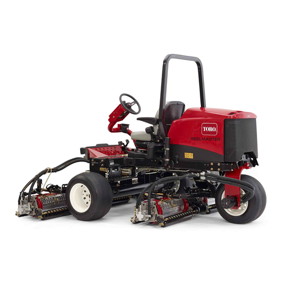
Page 19: Product Overview
Product Overview g216864 Figure 21 1. Engine hood 5. Seat adjustment lever 2. Seat 6. Front cutting units g020158 3. Control arm 7. Rear cutting units Figure 19 4. Steering wheel 1. Cutting-unit kickstand Secure the kickstand to the chain bracket with the Controls snapper pin (Figure... - Page 20 Mow/Transport Slide Using your heel, move the mow/transport slide (Figure 22) to the left to transport and to the right to mow. The cutting units will only operate in the M position and not lower in the T position. RANSPORT Important: The mow speed is set at the factory to 9.7 km/h (6 mph).
- Page 21 Engine Coolant Temperature Diagnostic Light Warning Light The diagnostic light (Figure 24) will illuminate if the system recognizes a system fault. The temperature warning light (Figure 24) glows if the engine coolant temperature is high. At this temperature, the cutting units are disabled. If the Fuel Gauge coolant temperature rises another 5.5°...
- Page 22 Reel Speed Control Knob The reel speed control controls the speed of the cutting units (Figure 27). The reel speed increases as you turn the knob counterclockwise. Refer to the reel speed chart decal (Figure 30), to determine the proper reel speed. g020248 Figure 27 1.
-
Page 23: Specifications
Contact your Authorized Service Dealer or authorized Toro distributor or go to www.Toro.com for a list of all approved attachments and accessories. To ensure optimum performance and continued safety certification of the machine, use only genuine Toro replacement parts and accessories. -
Page 24: Before Operation
• Do not store the machine or fuel container where • Contact your authorized Toro distributor if you wish there is an open flame, spark, or pilot light, such for more information on biodiesel. as on a water heater or other appliance. -
Page 25: Adjusting The Seat
Remove the fuel-tank cap. Raise the armrest and turn the knob, in either direction, to provide the best comfort (Figure 29). Fill the tank to the bottom of the filler neck. Do not overfill the tank. Install the cap. To prevent a fire hazard, wipe up any fuel that may have spilled. -
Page 26: During Operation
During Operation – Wait for all movement to stop. • Operate the machine only in good visibility and appropriate weather conditions. Do not operate During Operation Safety the machine when there is the risk of lightning. Rollover Protection System General Safety (ROPS) Safety •... -
Page 27: Starting The Engine
embankments, water hazards, or other CAUTION hazards. The machine could suddenly roll over Contact with moving parts could result if a wheel goes over the edge or the edge in injury. caves in. Establish a safety area between the machine and any hazard. Shut off the engine and wait for all –... - Page 28 decal121-7884 Figure 30 Model 03820 and 03910 1. 8-blade reel adjustment 3. Read the Operator’s Manual for information on adjusting the reel. 2. 11-blade reel adjustment decal133-4901 Figure 31 Model 03821 1. 8-blade reel adjustment 3. Read the Operator’s Manual for information on adjusting the reel.
-
Page 29: Adjusting The Lift-Arm Counterbalance
g034346 Figure 33 3. Additional hole locations 1. Spring 2. Spring actuator g020259 Move the spring actuator to the desired hole Figure 32 location and secure it with the bolt and the locknut. 1. Reel speed control knob Repeat the procedure on the remaining spring. Note: The reel speed can be increased or decreased to compensate for turf conditions. -
Page 30: Understanding The Diagnostic Light
• Tighten the screw and turn the ignition key to Fuses are blown. • It is not functioning correctly. Note: Normally the engine should start after the Check the electrical connections, input fuses, and above bleeding procedures are followed. However, if diagnostic light bulb to determine the malfunction. - Page 31 Remove the cover from the control panel. Diagnostic ACE, to change LED to “inputs displayed.” Locate the wire harness and loop-back connector (Figure 36). The Diagnostic ACE illuminates the LED associated with each of the inputs when that input switch is closed. Individually, change each of the switches from open to closed (i.e., sit on the seat, engage the traction pedal, etc.), and note that the...
-
Page 32: Operating Tips
LEDs are not correctly illuminated, this indicates machine immediately and correct the problem before an ECM problem. If this occurs, contact your continuing operation. Serious damage could occur if authorized Toro distributor for assistance. you operate the machine with a malfunction. Important: The Diagnostic ACE display must not be left connected to the machine. -
Page 33: After Operation
After Operation The following Toro parts are needed to bypass the check valve: • Toro Part No. 59-7410, diagnostic fitting After Operation Safety • Toro Part No. 354-79, diagnostic-fitting cap • Toro Part No. 95-8843, hydraulic hose General Safety •... -
Page 34: Hauling The Machine
Note: Do not exceed 7 to 11 N∙m (5 to 8 ft-lb) torque to close the valve. Pushing or Towing the Machine Forward Only If you need to push or tow the machine forward only, you can just rotate the bypass valve. Important: If you need to push or tow the machine in reverse, refer to... -
Page 35: Identifying The Tie-Down Points
Identifying the Tie-Down Points g198911 Figure 41 1. Tie-down loops... -
Page 36: Maintenance
• To ensure safe, optimal performance of the – Shut off the engine and remove the key. machine, use only genuine Toro replacement – Wait for all movement to stop. parts. Replacement parts made by other manufacturers could be dangerous, and such use •... - Page 37 Maintenance Service Maintenance Procedure Interval • If you are not using the recommended hydraulic fluid or have ever filled the reservoir with an alternative fluid, change the hydraulic fluid. Every 800 hours • If you are not using the recommended hydraulic fluid or have ever filled the reservoir with an alternative fluid, replace the hydraulic filter.
-
Page 38: Daily Maintenance Checklist
Daily Maintenance Checklist Duplicate this page for routine use. For the week of: Maintenance Check Item Mon. Tues. Wed. Thurs. Fri. Sat. Sun. Check the safety interlock operation. Check the brake operation. Check the engine-oil level. Check the cooling system fluid level. -
Page 39: Pre-Maintenance Procedures
Refer to your engine owner’s manual and cutting unit Operator's Manual for additional maintenance procedures. Note: Download a free copy of the electrical or hydraulic schematic by visiting www.Toro.com and searching for your machine from the Manuals link on the home page. Pre-Maintenance... -
Page 40: Lubrication
Lubrication Greasing the Bearings and Bushings Service Interval: Every 50 hours (daily when conditions are dusty and dirty). Park the machine on a level surface, lower the cutting units, engage the parking brake, shut off the engine, and remove the key from the ignition switch. g034347 Lubricate the grease fittings regularly with No. -
Page 41: Engine Maintenance
• Alternate oil: SAE 10W-30 or 5W-30 (all temperatures) Note: Toro Premium Engine Oil is available from your distributor in either 15W-40 or 10W-30 viscosity. Note: The best time to check the engine oil is when the engine is cool before it has been started for the day. -
Page 42: Servicing The Air Cleaner
Park the machine on a level surface, lower the cutting units, engage the parking brake, shut off the engine, and remove the key. Release the latches securing the air-cleaner cover to the air-cleaner body (Figure 53). Remove the cover from the air-cleaner body (Figure 53). -
Page 43: Changing The Engine Oil And Filter
Fuel System Install the cover orienting the rubber outlet valve in a downward position—between approximately Maintenance 5 o’clock to 7 o’clock when viewed from the end. Secure the cover latches. Servicing the Fuel Tank Changing the Engine Oil Service Interval: Every 2 years—Drain and clean the and Filter fuel tank. -
Page 44: Draining The Water Separator
Draining the Water Bleeding Air from the Separator Injectors Service Interval: Before each use or daily Note: Use this procedure only if the fuel system has been purged of air through normal priming procedures Park the machine on a level surface, lower the and the engine does not start;... -
Page 45: Electrical System Maintenance
Electrical System WARNING Incorrect battery cable routing could damage Maintenance the tractor and cables causing sparks. Sparks can cause the battery gasses to explode, resulting in personal injury. Electrical System Safety • Always disconnect the negative (black) • Disconnect the battery before repairing the battery cable before disconnecting the machine. -
Page 46: Drive System Maintenance
Drive System WARNING If the machine is not supported Maintenance adequately, it may accidentally fall, injuring anyone under the machine. Checking the Tire Pressure A front wheel and a rear wheel must be raised off the ground; otherwise, the Service Interval: Before each use or daily machine will move during adjustment. -
Page 47: Cooling System Maintenance
Cooling System CAUTION If the engine has been running, the Maintenance pressurized, hot coolant can escape and cause burns. Cooling System Safety • Do not open the radiator cap when the engine is running. • Swallowing engine coolant can cause poisoning; keep out of reach from children and pets. -
Page 48: Cleaning The Engine Cooling System
Cleaning the Engine Brake Maintenance Cooling System Adjusting the Parking Service Interval: Before each use or daily Brake Remove debris from the radiator daily. Clean it more frequently in dirty conditions. Service Interval: Every 200 hours—Check the Park the machine on a level surface, lower the adjustment of the parking brake. -
Page 49: Belt Maintenance
Belt Maintenance the engine, and remove the key from the ignition switch. Insert a nut driver or small piece of tubing onto Servicing the Engine Belts the end of the belt tensioning spring. Service Interval: After the first 10 hours—Check the WARNING condition and tension of all belts. -
Page 50: Controls System Maintenance
Controls System Hydraulic System Maintenance Maintenance Adjusting the Throttle Hydraulic System Safety • Park the machine on a level surface, lower the Seek immediate medical attention if fluid is injected cutting units, engage the parking brake, shut off into skin. Injected fluid must be surgically removed the engine, and remove the key from the ignition within a few hours by a doctor. -
Page 51: Hydraulic Fluid Specifications
This fluid is compatible with the elastomers used If the level is low, add the appropriate fluid to in Toro hydraulic systems and is suitable for a raise the level to the full mark. wide-range of temperature conditions. This fluid is compatible with conventional mineral oils, but for Install the dipstick and cap onto the filler neck. -
Page 52: Changing The Hydraulic Fluid
If the fluid becomes contaminated, contact your Install the reservoir cap. Start the engine and local Toro distributor because the system must be use all of the hydraulic controls to distribute the flushed. Contaminated fluid looks milky or black when hydraulic fluid throughout the system. -
Page 53: Cutting Unit System Maintenance
Cutting Unit System the engine, and remove the key from the ignition switch. Maintenance Clean around the filter mounting area. Place a drain pan under the filter (Figure 69) and remove the filter. Blade Safety A worn or damaged blade or bedknife can break, and a piece could be thrown toward you or bystanders, resulting in serious personal injury or death. -
Page 54: Using The Optional Gauge Bar
Using the Optional Gauge Start the engine and allow it to run at low idle speed. DANGER Use the gauge bar (Figure 70) to adjust the cutting Changing the engine speed while unit. Refer to the cutting unit Operator's Manual for the adjustment procedure. -
Page 55: Cleaning
Cleaning If the cutting units stall or become erratic while backlapping, select a higher reel speed setting until the speed stabilizes, then return the reel speed to setting 1 or to your desired speed. Washing the Machine To make an adjustment to the cutting units while Wash the machine as needed using water alone backlapping, turn the cutting units off by moving or with a mild detergent. -
Page 56: Storage
Clean the battery, terminals, and posts with a wire brush and baking-soda solution. Coat the cable terminals and battery posts with Grafo 112X skin-over grease (Toro Part No. 505-47) or petroleum jelly to prevent corrosion. Slowly charge the battery every 60 days for 24 hours to prevent lead sulfation of the battery. - Page 57 Notes:...
- Page 58 The Toro Company (“Toro”) respects your privacy. When you purchase our products, we may collect certain personal information about you, either directly from you or through your local Toro company or dealer. Toro uses this information to fulfil contractual obligations - such as to register your warranty, process your warranty claim or to contact you in the event of a product recall - and for legitimate business purposes - such as to gauge customer satisfaction, improve our products or provide you with product information which may be of interest.
- Page 59 While the exposure from Toro products may be negligible or well within the “no significant risk” range, out of an abundance of caution, Toro has elected to provide the Prop 65 warnings. Moreover, if Toro does not provide these warnings, it could be sued by the State of California or by private parties seeking to enforce Prop 65 and subject to substantial penalties.
- Page 60 Countries Other than the United States or Canada Customers who have purchased Toro products exported from the United States or Canada should contact their Toro Distributor (Dealer) to obtain guarantee policies for your country, province, or state. If for any reason you are dissatisfied with your Distributor's service or have difficulty obtaining guarantee information, contact your Authorized Toro Service Center.
Need help?
Do you have a question about the Reelmaster 3555 and is the answer not in the manual?
Questions and answers