Toro Reelmaster 3550 Operator's Manual
Traction unit
Hide thumbs
Also See for Reelmaster 3550:
- Operator's manual (24 pages) ,
- Installation instructions manual (12 pages) ,
- Operator's manual (112 pages)

Related Manuals for Toro Reelmaster 3550


Summary of Contents for Toro Reelmaster 3550
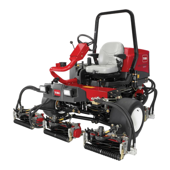
- Page 1 Form No. 3412-549 Rev A Reelmaster ® 3550 Traction Unit Model No. 03910—Serial No. 400000000 and Up *3412-549* A Register at www.Toro.com. Original Instructions (EN)
- Page 2 You are responsible for operating the product properly and safely. You may contact Toro directly at www.Toro.com for product and accessory information, help finding a dealer, or to register your product. Whenever you need service, genuine Toro parts, or additional...
-
Page 3: Table Of Contents
Contents Electrical System Maintenance ........40 Electrical System Safety...........40 Servicing the Battery..........40 Safety ................4 Checking the Fuses..........40 General Safety............4 Drive System Maintenance .........41 Safety and Instructional Decals ......... 4 Adjusting the Traction Drive for Neutral....41 Setup ................10 Cooling System Maintenance ........42 1 Installing the Cutting Units........11 Cooling System Safety..........42 2 Adjusting the Turf Compensation Spring....13... -
Page 4: Safety
Safety • Do not operate the machine without all guards and other safety protective devices in place and working on the machine. This machine has been designed in accordance with EN ISO • Keep clear of any discharge opening. Keep bystanders 5395:2013 (when appropriate decals are applied) and ANSI and pets a safe distance away from the machine. - Page 5 decal93-6688 93–6688 1. Warning—read the 2. Cutting hazard of hand or Operator’s Manual before foot—shut off the engine performing maintenance. and wait for all moving parts to stop. decal120-2102 120–2102 1. Read the Operator’s Manual decal106-6755 106-6755 1. Engine coolant under 3.
- Page 6 decal120-1683 120-1683 1. Warning—read the Operator's Manual; do not operate the 4. Warning—do not park the machine on slopes; engage the parking brake, lower the cutting units, shut off the engine, and machine unless you have received training. remove the ignition key before leaving the machine. 2.
- Page 7 decal120-1686 120-1686 (Affix over Part No. 120-1683 for CE) * This safety decal includes a slope warning required on the machine for compliance to the European Lawn Mower Safety Standard EN ISO 5395:2013. The conservative maximum slope angles indicated for operation of this machine are prescribed by and required by this standard. This machine complies with the industry standard stability test in the static lateral and longitudinal tests with the maximum recommended slope indicated on the decal.
- Page 8 decal121-7884 121-7884 1. 8-blade reel adjustment 3. Read the Operator’s Manual for information on adjusting the reel. 2. 11-blade reel adjustment...
- Page 9 decal120-2105 120-2105 1. Lower the reels. 5. Read the Operator’s Manual for 9. Engine—start information on starting the engine—1) Sit in the operator’s position; 2) Turn the key to the engine—preheat position; 3) Wait until the electrical preheat light turns off; 4) Turn the key to the engine—start position;...
-
Page 10: Setup
Setup Loose Parts Use the chart below to verify that all parts have been shipped. Procedure Description Qty. – No parts required Install the cutting units. – No parts required Adjust the turf compensation spring. Warning decal (120-1686) Install the CE decal, if required. Lock bracket Rivet Washer... -
Page 11: Installing The Cutting Units
Installing the Cutting Units g003949 No Parts Required Figure 4 1. Turf compensation spring 3. Spring tube Procedure 2. Rod bracket 1. Park the machine on a level surface, engage the parking brake, shut off the engine, and remove the key. B. - Page 12 g003979 Figure 8 1. Lift-arm shaft lynch pin and washer g003975 Figure 6 B. Insert the lift-arm yoke onto the carrier frame 1. Snapper pin 2. Cap shaft (Figure C. Insert the lift-arm shaft into the lift arm and 9. For the front cutting units, slide a cutting unit under secure it with the washer and lynch pin (Figure the lift arm while inserting the carrier frame shaft up...
-
Page 13: Adjusting The Turf Compensation Spring
Adjusting the Turf Compensation Spring No Parts Required g003948 Figure 10 Procedure 1. Lift-arm chain 3. Snapper pin The turf compensation spring (Figure 12) transfers weight 2. Chain bracket from the front to the rear roller. This helps to reduce a wave pattern in the turf, also known as marcelling or bobbing. -
Page 14: Installing The Ce Decal
3. While aligning the mounting holes, position the CE lock bracket and the hood-latch bracket onto the hood. Note: The lock bracket must be against the hood (Figure 14). Do not remove the bolt and nut from the Installing the CE Decal lock-bracket arm. -
Page 15: Using The Cutting Unit Kickstand
G012631 g012631 Figure 16 1. Bolt 3. Arm of hood-lock bracket 2. Nut Using the Cutting Unit g020158 g020158 Figure 17 Kickstand 1. Cutting unit kickstand Parts needed for this procedure: Secure the kickstand to the chain bracket with the snapper Cutting unit kickstand (Figure 18). -
Page 16: Product Overview
Tilt-Steering Lever Product Overview Pull the tilt-steering lever (Figure 19) back to tilt the steering wheel to the desired position. Then push the lever forward Controls to secure the position. Ignition Switch The ignition switch (Figure 21), used to start, shut off, and preheat the engine, has 3 positions: O REHEAT and S... -
Page 17: Parking Brake
Lower Mow/Raise Control Lever This lever (Figure 21) raises and lowers the cutting units and also starts and stops the reels when the reels are enabled in the mow mode. You cannot lower the cutting units when the mow/transport lever is in the T position. -
Page 18: Specifications
Contact your Authorized Service Dealer or Distributor or go to www.Toro.com for a list of all approved attachments and accessories. To best protect your investment and maintain optimal performance of your Toro equipment, count on Toro genuine parts. -
Page 19: Operation
Preferred oil: SAE 15W-40 (above 0ºF (-17ºC)) • Alternate oil: SAE 10W-30 or 5W-30 (all temperatures) Before Operation Safety Note: Toro Premium Engine Oil is available from your distributor in either 15W-40 or 10W-30 viscosity. Refer to the General Safety Parts Catalog for part numbers. -
Page 20: Filling The Fuel Tank
Monitor seals, hoses, and gaskets in contact with fuel as they may be degraded over time. • Expect plugging of the fuel filter for a time after converting to biodiesel blends. • Contact your authorized Toro distributor for more information on biodiesel. -
Page 21: Checking The Cooling System
If the engine has been running, the pressurized, hot coolant can escape and cause burns. Alternative fluids: If the Toro fluid is not available, you may use other conventional, petroleum-based fluids, provided that • Do not open the radiator cap when the engine they meet all the following material properties and industry is running. -
Page 22: Checking The Reel-To-Bedknife Contact
Synthetic, Biodegradable Hydraulic Fluid is available in 19 L (5 gallon) containers or 208 L (55 gallon) drums—see Checking the Tire Pressure the parts documentation or your Toro distributor for part numbers. Service Interval: Before each use or daily This high-quality, synthetic, biodegradable fluid has been The tires are over-inflated for shipping. -
Page 23: During Operation Safety
2. Slide the seat to the desired position and release the lever to lock it in position. Changing the Seat Suspension You can adjust the seat to provide a smooth and comfortable ride. Position the seat where you are most comfortable. To adjust it, turn the front knob in either direction to provide the best comfort (Figure... -
Page 24: Starting And Shutting Off The Engine
Do not use the machine as a towing vehicle. Engine • Use accessories, attachments, and replacement parts You may need to bleed the fuel system if any of the following approved by The Toro® Company only. situations have occurred; refer to Bleeding the Fuel System (page 27): Rollover Protection System (ROPS) •... -
Page 25: Setting The Reel Speed
Setting the Reel Speed the key to the S position to engage the starter TART motor. To achieve a consistent, high quality of cut and a uniform Note: Release the key when the engine starts. The key after cut appearance, it is important that you set the reel speed will move automatically to the O position. -
Page 26: Adjusting The Lift Arm Counterbalance
decal121-7884 Figure 32 1. 8-blade reel adjustment 3. Read the Operator’s Manual for information on adjusting the reel. 2. 11-blade reel adjustment Adjusting the Lift Arm 4. To set the reel speed, rotate the knob (Figure until the indicator arrow is in line with the number Counterbalance designating the desired setting. -
Page 27: Bleeding The Fuel System
g008891 Figure 35 1. Fuel-injection pump bleed screw g020250 Figure 34 5. Turn the key in the ignition switch to the O position. 3. Additional hole locations 1. Spring The electric fuel pump will begin operation, thereby 2. Spring actuator forcing air out around the air-bleed screw. -
Page 28: Understanding The Diagnostic Ace Display
Checking the Interlock Switches Service Interval: Before each use or daily The purpose of the interlock switches is to prevent the engine from cranking or starting unless the traction pedal is in the position, the Enable/Disable switch is in the EUTRAL position, and the Lower Mow/Raise control is in ISABLE... -
Page 29: After Operation Safety
LEDs are not correctly illuminated, this indicates an ECM 9. If a switch is closed and the appropriate LED does problem. If this occurs, contact your Toro distributor not turn on, check all wiring and connections to the for assistance. -
Page 30: Identifying The Tie-Down Points
In case of an emergency, you can tow the machine for a units (the front cutting units are timed to lower before the short distance; however, Toro does not recommend this as rear cutting units). To move forward and cut grass, press the a standard procedure. - Page 31 damage the machine or the cutting units. Use extra care when operating the machine on slopes. Drive slowly and avoid sharp turns on slopes to prevent roll-overs.
-
Page 32: Maintenance
Maintenance Note: Determine the left and right sides of the machine from the normal operating position. Recommended Maintenance Schedule(s) Maintenance Service Maintenance Procedure Interval • Torque the wheel nuts. After the first hour • Torque the wheel nuts. • Check the condition and tension of all belts. After the first 10 hours •... -
Page 33: Daily Maintenance Checklist
Immediately after every washing, regardless of the interval listed. Important: Refer to your engine owner’s manual for additional maintenance procedures. Note: To obtain an electrical schematic or a hydraulic schematic for your machine, visit www.Toro.com. Notation for Areas of Concern... -
Page 34: Service Interval Chart
Service Interval Chart decal120-2102 Figure 41 Pre-Maintenance Removing the Hood Procedures The hood may be easily removed to ease maintenance procedures in the engine area of the machine. 1. Unlatch and raise the hood. Pre-Maintenance Safety 2. Remove the hairpin cotter securing the hood pivot to •... -
Page 35: Removing The Battery Cover
Removing the Battery Cover Loosen the knobs and remove the battery cover (Figure 43). Note: Refer to Servicing the Battery (page 40) for more information. g008874 Figure 43 1. Battery cover... -
Page 36: Lubrication
Lubrication • Rear lift-arm pivots and lift cylinders (3 each side); refer Figure Greasing the Bearings and Bushings Service Interval: Every 50 hours (daily when conditions are dusty and dirty). Park the machine on a level surface, lower the cutting units, engage the parking brake, shut off the engine, and remove the key from the ignition switch. -
Page 37: Engine Maintenance
Engine Maintenance • Mow/transport slide (Figure Engine Safety • Shut off the engine before checking the oil or adding oil to the crankcase. • Do not change the governor speed or overspeed the engine. g008902 Servicing the Air Cleaner Figure 49 Service Interval: Every 200 hours (more frequently in extremely dusty or dirty conditions). -
Page 38: Changing The Engine Oil And Filter
g020086 g020086 Figure 52 1. Engine-oil drain plugs 3. Remove the oil filter (Figure 53). g002401 Figure 51 1. Air-cleaner cover 2. Filter 6. Inspect the new filter for shipping damage, checking the sealing end of the filter and the body. Important: Do not use a damaged element. -
Page 39: Fuel System Maintenance
Fuel System 4. Tighten the valve after draining. Maintenance Changing the Fuel Filter Canister Servicing the Fuel Tank Service Interval: Every 400 hours Service Interval: Every 2 years—Drain and clean the fuel 1. Park the machine on a level surface, lower the cutting tank. -
Page 40: Electrical System Maintenance
Electrical System Keep the top of the battery clean by washing it periodically with a brush dipped in ammonia or bicarbonate of soda Maintenance solution. Flush the top surface with water after cleaning. Do not remove the filler caps while cleaning. The battery cables must be tight on the terminals to provide Electrical System Safety good electrical contact. -
Page 41: Drive System Maintenance
Drive System 4. Start the engine and rotate the cam hex in both directions to determine the mid position of the neutral Maintenance span. 5. Tighten the locknut securing the adjustment. Adjusting the Traction Drive 6. Shut off the engine. 7. -
Page 42: Cooling System Maintenance
Brake Maintenance Cooling System Maintenance Adjusting the Parking Brake Cooling System Safety Service Interval: Every 200 hours—Check the adjustment of the parking brake. • Swallowing engine coolant can cause poisoning; 1. Park the machine on a level surface, lower the cutting keep it out of reach of children and pets. -
Page 43: Belt Maintenance
Belt Maintenance WARNING The spring is under a heavy load and could cause personal injury Servicing the Engine Belts Use caution when de-tensioning the spring. Service Interval: After the first 10 hours—Check the condition and tension of all belts. 3. Push down and forward on the spring end (Figure Every 100 hours—Check the condition and tension to unhook it from the bracket and release tension on... -
Page 44: Controls System Maintenance
Changing the Hydraulic Filter Service Interval: After the first 10 hours Every 200 hours/Yearly (whichever comes first) Use a genuine Toro replacement filter, Part No. 86-3010. Important: Use of any other filter may void the warranty on some components. g020336 Figure 61 1. -
Page 45: Changing The Hydraulic Fluid
Changing the Hydraulic Fluid Service Interval: Every 400 hours If the fluid becomes contaminated, contact your local Toro distributor because the system must be flushed. Contaminated fluid looks milky or black when compared to clean oil. 1. Park the machine on a level surface, lower the cutting... -
Page 46: Cutting Unit System Maintenance
Backlapping the Cutting Units Cutting Unit System Maintenance WARNING Contact with the reels or other moving parts can Cutting Unit Safety result in personal injury. • Keep your fingers, hands, and clothing away A worn or damaged cutting unit can break, and a piece of from the reels and other moving parts. -
Page 47: Storage
D. Clean the battery, terminals, and posts with a wire brush and baking-soda solution. E. Coat the cable terminals and battery posts with Grafo 112X skin-over grease (Toro Part No. 505-47) or petroleum jelly to prevent corrosion. F. Either store the battery on the shelf or on the machine in a cool area. -
Page 48: Preparing The Engine
Preparing the Engine 1. Drain the engine oil from the oil pan and replace the drain plug. 2. Remove and discard the oil filter. Install a new oil filter. 3. Refill the oil pan with approximately 3.8 L (4 US qt) of SAE 15W-40 motor oil. - Page 49 Notes:...
- Page 50 Notes:...
- Page 51 The Way Toro Uses Information Toro may use your personal information to process warranty claims, to contact you in the event of a product recall and for any other purpose which we tell you about. Toro may share your information with Toro's affiliates, dealers or other business partners in connection with any of these activities. We will not sell your personal information to any other company.
- Page 52 Countries Other than the United States or Canada Customers who have purchased Toro products exported from the United States or Canada should contact their Toro Distributor (Dealer) to obtain guarantee policies for your country, province, or state. If for any reason you are dissatisfied with your Distributor's service or have difficulty obtaining guarantee information, contact the Toro importer.
Need help?
Do you have a question about the Reelmaster 3550 and is the answer not in the manual?
Questions and answers