AEMC 6416 Application Note
Clamp-on ground resistance tester
Hide thumbs
Also See for 6416:
- Service/calibration manual (16 pages) ,
- User manual (41 pages) ,
- User manual (45 pages)
Advertisement
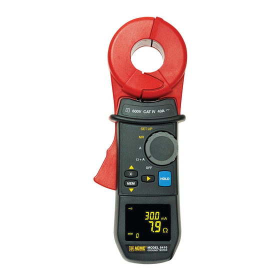
Clamp-On Ground Resistance Tester
Model 6416
Step-by-Step Usage Guide
1. Turn instrument on by rotating the selector knob to the "Ω+A"
position.
2. Allow instrument to boot up and begin beeping with 0RΩ displayed
on screen.
3. Check calibration — locate the 5Ω calibration gauge supplied with
the tester and clamp the meter around any leg of the gauge.
4. Observe instrument reading – the reading should be within 0.2Ω of
gauge specification (5Ω). If reading is correct proceed to step 5.
If not, clean instrument and repeat steps 3 and 4. If you are not
able to get the instrument to read within 0.2Ω after cleaning
instrument, do not proceed. Have the instrument repaired.
5. Remove instrument from gauge. Observe instrument reading with
nothing in the clamps. The reading should be 0RΩ
If this condition is observed, continue to step 6. If
not, clean instrument (see instructions below) and
repeat steps 3 through 5. If, after cleaning instru-
ment, you are still unable to get the instrument to
perform as described in steps 4 and 5, open the
jaws approximately 1/2 inch and let them snap
shut. Make sure that the jaws close properly. If
the unit still does not perform properly, do not
proceed. Have the instrument repaired.
6. Switch instrument to Current Mode. (Rotate
selector switch to the "A" position for Amps)
7. Clamp instrument around the ground wire or rod.
8. Observe reading – if less than 1.0A, proceed to step 9. If between 1.0 and 5.0A,
make note of reading and continue to step 9. If greater than 5A, terminate test and
remove instrument from the ground wire or rod and correct the problem before
re-testing.
9. Switch instrument to Resistance (Ω+A) mode. (Rotate selector switch to the "Ω+A"
position)
10. Wait for reading to stabilize and record reading. Lock reading on the display by
pressing "HOLD".
11. Remove instrument from ground wire or rod and re-clamp to gauge.
12. Observe reading – the reading should be within 0.2Ω of gauge value. If reading is
OK – measurement is valid. If reading is wrong, clean instrument (see instructions
below) and repeat from step 4.
Cleaning the Heads
To ensure optimum performance, it is important to keep the probe jaw mating surfaces clean at all times.
Failure to do so may result in erroneous readings. To clean the probe jaws, use a lint free cloth or, if the
jaws are pitted, use a very fine sandpaper (600 grit) to avoid scratching the surface, then gently clean with
a soft cloth. Make sure that the instrument is oriented such that no debris or filings will fall into the unit while
cleaning. Check with your finger afterwards to be sure that no foreign material remains on the jaw surfaces
(both top and bottom).
Technical Assistance (800) 343-1391
Step 3
99-MAN 100456
www.aemc.com
Advertisement
Table of Contents

Related Manuals for AEMC 6416


Summary of Contents for AEMC 6416
- Page 1 Clamp-On Ground Resistance Tester Clamp-On Ground Resistance Tester Model 6416 Model 6416 Step-by-Step Usage Guide Step-by-Step Usage Guide 1. Turn instrument on by rotating the selector knob to the “Ω+A” 1. Turn instrument on by rotating the selector knob to the “Ω+A” position. position. 2. Allow instrument to boot up and begin beeping with 0RΩ displayed 2. Allow instrument to boot up and begin beeping with 0RΩ displayed on screen. on screen. 3. Check calibration — locate the 5Ω calibration gauge supplied with 3. Check calibration — locate the 5Ω calibration gauge supplied with the tester and clamp the meter around any leg of the gauge. the tester and clamp the meter around any leg of the gauge. 4. Observe instrument reading – the reading should be within 0.2Ω of 4. Observe instrument reading – the reading should be within 0.2Ω of...
- Page 2 Figure A or an equivalent circuit, shown in Figure B. If voltage E is applied to any measured grounding system. Figure A or an equivalent circuit, shown in Figure B. If voltage E is applied to any measured grounding system. Rx through a special transformer, current I flows through the circuit. Rx through a special transformer, current I flows through the circuit. Therefore, E/I = Rx is established. If it is detected with E kept constant, measured grounding resistance can be Therefore, E/I = Rx is established. If it is detected with E kept constant, measured grounding resistance can be obtained. Refer again to Figures A and B. Current is fed to a special transformer via a power amplifier from a obtained. Refer again to Figures A and B. Current is fed to a special transformer via a power amplifier from a 2083 Hz constant voltage oscillator. This current is detected by a detection CT. Only the 2083 Hz signal fre- 2083 Hz constant voltage oscillator. This current is detected by a detection CT. Only the 2083 Hz signal fre- quency is amplified by a filter amplifier. This occurs before the A/D conversion and after synchronous rectifica- quency is amplified by a filter amplifier. This occurs before the A/D conversion and after synchronous rectifica- tion. It is then displayed on the screen of the Model 6416 meter. tion. It is then displayed on the screen of the Model 6416 meter. The filter amplifier is used to cut off both earth current at commercial frequency and high-frequency noise. The filter amplifier is used to cut off both earth current at commercial frequency and high-frequency noise. Voltage is detected by coils wound around the injection CT, which is then amplified, rectified, and compared by Voltage is detected by coils wound around the injection CT, which is then amplified, rectified, and compared by a level comparator. If the clamp is not closed properly, an “open jaw” annunciator appears on the display. a level comparator. If the clamp is not closed properly, an “open jaw” annunciator appears on the display. FIGURE A FIGURE B FIGURE A FIGURE B The important points to consider for proper use of the clamp-on ground tester are: The important points to consider for proper use of the clamp-on ground tester are: 1.
Need help?
Do you have a question about the 6416 and is the answer not in the manual?
Questions and answers